Patent application title: ROTOR FOR A STEAM TURBINE
Inventors:
Jorg Devries (Wesel, DE)
Assignees:
SIEMENS AKTIENGESELLSCHAFT
IPC8 Class: AF01D1512FI
USPC Class:
415101
Class name: Rotary kinetic fluid motors or pumps axially opposed working fluid paths to or from runner (e.g., end balance, etc.) plural, separate, parallel, simultaneous flow paths
Publication date: 2015-05-21
Patent application number: 20150139780
Abstract:
A turbomachine is provided, wherein the rotor comprises a planetary gear
on which low-pressure end stage blades are arranged, wherein the
planetary gear is designed in such a way that the frequency of the
rotating blades is lower than the frequency of the rotor.Claims:
1. A rotor for a turbomachine having a planetary gearset comprising a
shaft and a crown wheel which is arranged about the shaft and can adapted
to be arranged in a rotationally fixed manner, wherein the crown wheel
has internal teeth which interact with multiple internal planet gears, a
planet disk which is arranged about the shaft and on which the planet
gears are rotatably arranged, wherein the shaft has a sun gear which
interacts with the planet gears and rotor blades which are arranged on
the planet disk, wherein rotor blade stages formed of further rotor
blades are arranged fixedly on the rotor.
2. The rotor as claimed in claim 1, wherein the planet disk is sealed with respect to the shaft.
3. The rotor as claimed in claim 2, wherein an oil seal is arranged between the shaft and the planet disk.
4. The rotor as claimed in claim 2, wherein a steam seal is arranged between the shaft and the planet disk.
5. The rotor as claimed in claim 1, wherein at least four planet gears are arranged.
6. The rotor as claimed in claim 1, wherein the planet gears, the sun gear and the crown wheel are dimensioned such that a shaft rotational frequency of the shaft is higher than the planet disk rotational frequency of the planet disk.
7. The rotor as claimed in claim 1, wherein the planet disk is connected to a rotor disk.
8. The rotor as claimed in claim 7, wherein the rotor blades are arranged on the rotor disk.
9. A steam turbine having a rotor as claimed in claim 1.
10. The steam turbine as claimed in claim 9, wherein the steam turbine is of double-flow configuration and each flow channel has a planetary gearset as claimed in claim 1.
Description:
CROSS REFERENCE TO RELATED APPLICATIONS
[0001] This application is the US National Stage of International Application No. PCT/EP2013/057185 filed Apr. 5, 2013, and claims the benefit thereof. The International Application claims the benefit of European Application No. EP12166935 filed May 7, 2012. All of the applications are incorporated by reference herein in their entirety.
FIELD OF INVENTION
[0002] The invention relates to a rotor for a turbomachine. The invention further relates to a steam turbine.
BACKGROUND OF INVENTION
[0003] Steam turbines, which are used for the local supply of power and can be considered an embodiment of a turbomachine, are relatively large and are thus accordingly heavy. Such steam turbines can weigh well over 100 tonnes. A steam turbine essentially comprises a rotatably mounted component, also referred to as a shaft. This shaft comprises rotor blades which are arranged fixed to the shaft surface. Such a shaft is rotatably mounted inside a casing, wherein the casing comprises guide vanes which, together with a rotor blade, represent a turbine stage.
[0004] In operation, the shaft of a steam turbine rotates preferably at 50 Hz or 60 Hz. Such high rotational frequencies lead to enormous centrifugal forces on the rotor blades. In particular, the end stages of a low-pressure steam turbine are accordingly large and thus experience a particularly large centrifugal force.
[0005] For technical reasons, the shafts of the steam turbines are operated at a constant rotational speed. In order to nonetheless be able to build relatively large end stages, lower-density materials--which therefore experience smaller centrifugal forces--are used. An example of such a material is titanium, which is used in some end stages. Other solutions may be possible, such that the fixed rotational frequency is reduced, e.g. a half-speed rotational frequency. It would also be possible to reduce the rotational frequency using transmission machines.
SUMMARY OF INVENTION
[0006] It is an object of the invention to propose a shaft for a turbomachine, which is suitable for relatively high frequencies.
[0007] This object is achieved with a rotor for a turbomachine having a planetary gearset comprising a crown wheel which is arranged about the rotor and is arranged in a rotationally fixed manner, wherein the crown wheel has internal teeth which interact with multiple internal planet gears, a planet disk which is arranged about the shaft and on which the planet wheels are rotatably arranged, wherein the shaft has a sun gear which interacts with the planet gears and a rotor disk having rotor blades which are arranged on the planet disk.
[0008] This thus adopts the path of changing not the frequency of the shaft but in particular the end stage comprising the rotor blades on the shaft. To that end, a planetary gearset is considered, which has the advantage that the frequency of the shaft is reduced to the frequency of the planetary disk, on which the rotor blades are arranged. This substantially reduces the centrifugal forces on the rotor blades of the end stage. The consequence of this is that, instead of the material titanium, mentioned as an example, it is possible to use another material which, although heavier, is stronger, such as steel.
[0009] As a consequence of the lower frequency at the end stage, this end stage can now be designed with larger cross sections in accordance with the physically limiting centrifugal force. By selecting low-density materials, the trailing cross section can be enlarged further, as hitherto also in solutions without a planetary gearset.
[0010] Advantageous refinements are indicated in the subclaims.
[0011] Thus, in a first advantageous refinement, the planetary gearset is sealed with respect to the shaft. According to aspects of the invention, this is effected using an oil seal between the shaft and the planet disk or the rotor disk. Equally, in an alternative embodiment of the invention, a steam seal between the shaft and the planet disk is possible. The steam flowing during operation should flow only through the flow duct and with as few losses as possible. Consequently, all possible leaks between the rotating and static components should be avoided.
[0012] In one advantageous refinement, the planetary gearset has at least four planet gears. This leads to increased stability of the shaft and leads to a lower risk of the planetary gearset failing.
[0013] According to aspects of the invention, the shaft can be used for both single-flow and double-flow steam turbines. The invention will now be explained in more detail with reference to the following exemplary embodiment.
BRIEF DESCRIPTION OF THE DRAWINGS
[0014] In the figures:
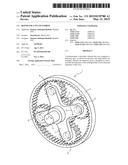
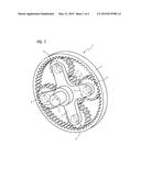
[0015] FIG. 1 shows a planetary gearset for a shaft;
[0016] FIG. 2 shows the cross section of a steam turbine having an end stage according to the invention.
DETAILED DESCRIPTION OF INVENTION
[0017] FIG. 1 shows a planetary gearset 1 which comprises multiple individual components. The planetary gearset 1 comprises a crown wheel 2 which has teeth on its inner side. This crown wheel 2 has a larger diameter than the diameter of a shaft 3. The shaft 3 has a sun wheel 4 which has teeth 5 on its outer circumference. In FIG. 1, for reasons of clarity, only two teeth are provided with the reference sign 5. The teeth 5 of the sun gear 4 engage in corresponding teeth of a planet gear 6.
[0018] The planet gears 6, the crown wheel 2 and the sun gear 4 are thus arranged in one plane.
[0019] The planet gears 6 are held by a planet disk 7, such that the planet gears 6 are arranged rotatably on the planet disk 7. The crown wheel 2 is arranged in a rotationally fixed manner. In this context, the crown wheel can be rigidly connected to the casing 11.
[0020] Thus, a rotation 8 of the shaft 3 on the sun gear 4 is transmitted to the planet gear 6. The planet gear 6 thus rotates about an axis of rotation. The consequence of this is that, as a result of the planet gear 6 engaging in the toothing of the crown wheel 2, the planet disk 7 is set in motion. The planet disk 7 thus also rotates and executes a rotation 9. By selecting suitable diameters for the crown wheel 2 and the planet gears 6, it is possible to effect a marked reduction in the frequency of the planet disk 7 with respect to the frequency of the shaft 3.
[0021] In a first embodiment, the rotor blades 17 are arranged on the planet disk 7.
[0022] In an alternative embodiment, a rotor disk 16 is force-fitted onto the planet disk 7. Rotor blades 17 (not shown in FIG. 1) are arranged on the rotor disk 16. Further rotor blades 18, forming a blade stage, are arranged on the rotor and rotate with a higher frequency than the rotor blades connected to the planetary gearset. The further rotor blades 18, which are fixedly connected to the rotor, are arranged upstream, as seen in a flow direction 19 of the main flow, of the rotor blades 17 connected to the planetary gearset. For reasons of clarity, only one blade stage is shown in FIG. 2.
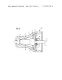
[0023] FIG. 2 shows the arrangement of the planetary gearset 1 in a turbomachine 10. The turbomachine 10, embodied as a steam turbine, has a casing 11 on the inner side of which are arranged guide vanes 12. In FIG. 2, only two guide vanes are provided with the reference sign 12. The remaining guide vanes are not shown for reasons of clarity. A flow duct 13 is formed between the shaft 3 and the casing 11, which duct is formed by various guide vanes and rotor blades (not shown). Steam, which flows into the steam turbine via an inlet opening 14, flows through this flow duct 13. The shaft 3 rotates about an axis of rotation 15. This frequency is approximately constant. By means of the planetary gearset 1, the planet disk 7 rotates at a lower frequency. A rotor disk 16 with rotor blades 17 of an end stage is arranged on the planet disk 7.
[0024] These rotor blades 17 now experience a smaller centrifugal force than if the rotor blades 17 had been arranged directly on the shaft surface.
[0025] The steam turbine represented in FIG. 2 is a single-flow steam turbine. This means that the steam, which enters the flow duct 13 via the inflow opening 14, flows only in one direction. The invention can equally be used in double-flow steam turbines. This means that the steam enters a steam turbine via an inflow opening and thence flows further in each of two flow channels which exhibit flow directions 180° apart. In such double-flow steam turbines, two planetary gearsets 1 can be used, in order to configure each of the end stages according to the invention. This means that the frequency of the end stages of the double-flow steam turbine is configured such that, with respect to identical end stages without a planetary gearset, the centrifugal forces are lower as a result of the lower frequency.
User Contributions:
Comment about this patent or add new information about this topic:
Images included with this patent application:
 |  |
 |
| Similar patent applications: | |
| Date | Title |
|---|---|
| 2013-03-14 | Steam turbine |
| 2013-08-29 | Steam turbine |
| 2014-08-21 | Steam turbine |
| 2014-09-18 | Steam turbine |
| 2014-09-18 | Steam turbine |
| New patent applications in this class: | |
| Date | Title |
|---|---|
| 2014-07-24 | Rotary pump comprising a rotor and delivery elements |
| 2012-05-24 | Self-aligning flow splitter for steam turbine |
| 2009-08-06 | Systems and methods for internally cooling a wheel of a steam turbine |
| Top Inventors for class "Rotary kinetic fluid motors or pumps" | |
| Rank | Inventor's name |
|---|---|
| 1 | Gabriel L. Suciu |
| 2 | Frederick M. Schwarz |
| 3 | United Technologies Corporation |
| 4 | Brian D. Merry |
| 5 | Craig M. Beers |