Patent application title: SMART TEMPERATURE CONSERVATION CONTAINER
Inventors:
Ching-Cheng Wu (Taoyuan County, TW)
Chih-Liang Fan (Taoyuan County, TW)
Te-Lun Kao (Taoyuan County, TW)
Assignees:
AQUAWAYS Co., Ltd
IPC8 Class: AA47G1922FI
USPC Class:
2064591
Class name: Special receptacle or package with indicator (i.e., variable information exhibiting means)
Publication date: 2015-05-21
Patent application number: 20150136629
Abstract:
A smart temperature conservation container comprises a container main
body, a cover body, at least a display unit, a temperature sensor, a
controller and a power supply module. A containing space of the container
main body is provided for containing liquid. The cover body covers the
container main body to seal the containing space. The display unit, the
temperature sensor, the controller and the power supply module are
disposed to the container main body. The temperature sensor can perform
temperature sensing for liquid contained in the containing space to
generate a signal that is further transmitted to the controller so that
the display unit can perform correspondingly display to allow the user to
understand the temperature of the liquid contained in the temperature
conservation container through the display unit.Claims:
1. A smart temperature conservation container comprising: a container
main body having a containing space and an opening communicating with the
containing space, the containing space for containing liquid; a cover
body covered to the opening of the containing main body to seal the
containing space; at least a display unit disposed to the container main
body and forming display effect toward an exterior of the container main
body; a temperature sensor disposed to the container main body to perform
temperature sensing for the liquid received in the containing space so as
to generate a signal; a controller disposed to the container main body to
respectively connect the display unit and the temperature sensor to
receive the signal that is further transmitted to the display unit for
correspondingly displaying; and a power supply module, disposed to the
container main body, for connecting the controller to provide power
source.
2. The smart temperature conservation container of claim 1, wherein the controller is further connected to a start-up unit, and the start-up unit is disposed to the container main body, and the start-up unit receives an exterior signal to enable the power supply module supplying power or not through a control of the controller.
3. The smart temperature conservation container of claim 2, wherein the start-up unit is an optical sensor.
4. The smart temperature conservation container of claim 2, wherein the start-up unit is a gravity directional sensor.
5. The smart temperature conservation container of claim 2, wherein the start-up unit is a touch sensor.
6. The smart temperature conservation container of claim 1, wherein the display unit is a liquid crystal display, a flexible display or a seven-segment display.
7. The smart temperature conservation container of claim 1, wherein a connector is further disposed between the display unit and the controller to connect the display unit and the controller.
8. The smart temperature conservation container of claim 1, wherein the power supply module is disposed with at least a battery and a charging insertion slot connected to the battery, and the charging insertion slot is exposed to the container main body.
Description:
BACKGROUND OF THE INVENTION
[0001] 1. Field of the Invention
[0002] The invention relates to a smart temperature conservation container, and more particularly to a smart temperature conservation container capable of providing related information of liquid inside a temperature conservation container to a user.
[0003] 2. Description of the Related Art
[0004] Temperatures of drink contained inside cups (bottles) in the past may quickly change due to generated heat or absorbed heat after placing them for a while at normal temperature, and such temperatures are gradually close to outside temperature to achieve the state of temperature balancing finally. Therefore, someone provides a temperature container, by utilizing heat insulation, that prevents heat of inside drink from being cooled down due to dissipation or being raised due to exterior heat absorption so that drink contained in the temperature conservation container can be retained for long term condition at warming/hot or cold state, and the cups (bottles) bodies are no need to be frequently placed in a refrigerator for conservation and are no need to be reheated by a heating device, thus reducing consumed energy required by changing temperature of drink again.
[0005] Although the vacuum bottles can provide certain temperature conservation effect, the drink therein can be gradually cooled down in accordance with time. Moreover, normal temperature conservation containers do not provide related information of inside temperature of the temperature conservation container to the user. Consequently, the user may not obtain current temperature of the drink to determine whether or not the drink can be drunk, resulting in carelessly scald when the user drinks. it
SUMMARY OF THE INVENTION
[0006] Therefore, upon the foregoing problems of prior art, it is an objective of the present invention to provide a smart temperature conservation container, and more particularly to the smart temperature conservation container capable of providing related information of liquid inside a temperature conservation container to a user.
[0007] To achieve the foregoing objective, the smart temperature conservation container according to the invention comprises a container main body, a cover body, at least a display unit, a temperature sensor, a controller and a power supply module. A containing space inside the container main body can contain liquid. The cover body is disposed to the container main body to seal the containing space. The display unit, the temperature sensor, the controller and the power supply module can be disposed to the container main body.
[0008] The temperature sensor can perform temperature sensing for liquid contained in the containing space to generate a signal, and the signal is transmitted to the controller so that the display unit can perform correspondingly display to allow the user to obtain temperature of liquid contained in the temperature conservation container.
BRIEF DESCRIPTION OF THE DRAWINGS
[0009] The detailed structure, operating principle and effects of the present invention will now be described in more details hereinafter with reference to the accompanying drawings that show various embodiments of the invention as follows.
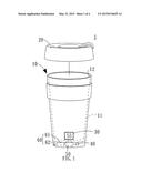
[0010] FIG. 1 is a structural three-dimensional diagram of a temperature conservation container according to the invention;
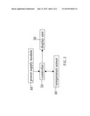
[0011] FIG. 2 is a block diagram of a temperature conservation container according to the invention;
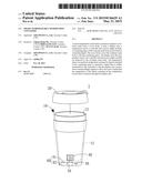
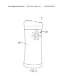
[0012] FIG. 3 is another structural three-dimensional diagram of a temperature conservation container according to the invention;
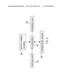
[0013] FIG. 4 is another block diagram of a temperature conservation container according to the invention;
DETAILED DESCRIPTION OF THE PREFERRED EMBODIMENTS
[0014] The technical content of the present invention will become apparent by the detailed description of the following embodiments and the illustration of related drawings as follows.
[0015] With reference to FIG. 1 for a three-dimensional diagram of a temperature conservation container according to the invention and FIG. 2 for a block diagram of a temperature conservation container according to the invention are depicted. The temperature conservation container 1 according to the invention comprises a container main body 10, a cover body 20, at least a display unit 30, a temperature sensor 40, a controller 50 and a power supply module 60.
[0016] The container main body 10 has a containing space 11 and an opening 12 communicating with the containing space 11. The containing space 11 can contain liquid.
[0017] The cover body 20 can cover the opening 12 of the container main body 10 and the display unit 30 form a display effect toward the exterior of the container main body 10, wherein the display unit 30 can be a liquid crystal display, a flexible display or a seven-stage display (as shown in FIG. 3).
[0018] The temperature sensor 40 is disposed to the container main body 10 and could perform temperature sensing for liquid contained in the containing space 11 to generate signals.
[0019] The controller 50 is disposed to the container main body 10 to respectively connect the display unit 30 and the temperature sensor 40 to receive the signal. The signal is further transmitted to the display unit 30 to perform correspondingly display. A connector (not shown in the figure) is further disposed between the display unit 30 and the controller 50 to connect the display unit and the controller.
[0020] The power supply module 60 is disposed to the container main body 10 to connect the controller 50 to supply power source, wherein the power supply module 60 is disposed with at least a battery 61 and a charging insertion slot 62 connected to the battery 61. The charging insertion slot 62 is exposed to the container main body 10. In the embodiment, the charging insertion slot 62 is an universal series bus (USB).
[0021] When the container main body 10 contains liquid, the temperature sensor 40 can perform temperature sensing for the liquid contained inside the containing space 11 to generate a signal. The signal is transmitted to the display unit 30 through the controller 50 to perform correspondingly display. For example, a measured temperature value (i.e. 55 degrees Celsius) can be directly displayed, or the seven-segment display can be utilized as a display unit for displaying temperatures so that the user can determine whether or not the current temperature of the liquid inside the temperature conservation container is too hot to prevent the user from being scaled while in drinking.
[0022] Moreover, the controller 50 is further connected to a start-up unit 70 as shown in FIG. 4. The start-up unit 70 is disposed to the container main body (not shown in the figure). An external signal is received by the start-up unit 70 to allow the power supply module 60 supplying power or not through the control of the controller 50, thereby achieving power saving effect. The start-up unit 70 can be an optical sensor for generating the signal to enable the power supply module 60 supplying power to the display unit 30 for normally emitting light and displaying when ambient light is not good enough. Of course, the start-up unit 70 can also be a gravity directional sensor or a touch sensor.
[0023] While the means of specific embodiments showing a preferable and feasible smart temperature conservation container according to the present invention has been described by reference drawings, numerous modifications and variations could be made thereto by those skilled in the art without departing from the scope and spirit of the invention set forth in the claims. The modifications and variations should in a range limited by the specification of the present invention.
User Contributions:
Comment about this patent or add new information about this topic:
Images included with this patent application:
 |  |
 |  |
 |
| Similar patent applications: | |
| Date | Title |
|---|---|
| 2016-04-21 | Coated food-contacting containers |
| 2016-04-14 | Substrate storage container |
| 2016-04-28 | Multiple chamber fluid container |
| 2016-04-28 | Dual compartment pouch having pressure-openable non-seamed line |
| 2016-05-05 | Substrate storing container |
| New patent applications in this class: | |
| Date | Title |
|---|---|
| 2019-05-16 | Carton with tab |
| 2018-01-25 | Apparatus and method for monitoring cargo conditions |
| 2016-09-01 | Product and package with a photosensitive use-evident feature |
| 2016-09-01 | Reservoir |
| 2016-07-07 | Enclosable container system and sealing indicator |
| Top Inventors for class "Special receptacle or package" | |
| Rank | Inventor's name |
|---|---|
| 1 | Donald E. Weder |
| 2 | Brett R. Glass |
| 3 | Daniel Lee Bizzell |
| 4 | Andrea Biondi |
| 5 | Nicole E. Glass |