Patent application title: Multi-Stage Pump Having Reverse Bypass Circuit
Inventors:
Ronald J. Forni (Lexington, MA, US)
Ronald J. Forni (Lexington, MA, US)
IPC8 Class: AF04B2500FI
USPC Class:
417244
Class name: Pumps successive stages
Publication date: 2015-03-19
Patent application number: 20150078927
Abstract:
A multi-stage pump includes a pump head having at least two compression
stages disposed in series With espect to the direction of flow of fluid
through the pump, and a reverse fluid bypass circuit including a fluid
passageway through which fluid flowing between upstream and downstream
ones of the compression stages can he circulated back upstream of the
upstream compression stage. The reverse fluid bypass circuit may restrict
or stop the flow of fluid through the fluid passageway as long as the
pressure differential across the fluid passage is below a. predetermined
value. To this end, the reverse fluid bypass circuit may be configured to
restrict the flow of fluid while the fluid is in its transitional or
molecular flow regime, and allow the flow of fluid while the fluid is in
its viscous flow regime.Claims:
1. A multi-stage pump comprising: an inlet portion having a pump inlet
and constituting a low pressure side of the pump where fluid is drawn
into the pump, and an exhaust portion having a pump outlet and
constituting a compression side where fluid is discharged from the pump
at pressure greater than that of the fluid at the low pressure side; a
pump head having an inlet opening to which the pump inlet extends, an
exhaust opening leading to the pump outlet, at least two compression
stages disposed in series with respect to the direction of flow of fluid
through the pump, and a fluid bypass circuit, and wherein each of the
compression stages has an ingress through which the fluid enters the
stage and an egress through which the fluid exits the stage, a flow path
along which fluid flows from the pump inlet to the pump outlet extends in
the pump between the pump inlet and an upstream one of the compression
stages, between the egress of the upstream one of the compression stages
and the ingress of a downstream one of the compression stages, and
between the egress of the downstream one of the compression stages and
the pump outlet, and the fluid bypass circuit defines a fluid passageway
discrete from the flow path and connected to the flow path at a first
location between the egress of one of the compression stages and the
ingress of the next compression stage downstream therefrom and at a
second location upstream of the ingress of said one of the compression
stages.
2. The pump as claimed in claim 1, wherein the fluid bypass circuit comprises a valve disposed in-line with the fluid passageway.
3. The pump as claimed in claim 2 wherein the valve is a spring-biased check valve that opens when the differential pressure across the fluid passageway, as between the second and first locations, is greater than a predetermined value.
4. The pump as claimed in claim 1, wherein the fluid bypass circuit comprises a labyrinth seal providing a flow restriction between the first and second locations.
5. The pump as claimed in claim 1, wherein the fluid bypass circuit comprises a capillary tube providing a flow restriction between the first and second locations.
6. The pump as claimed in claim , wherein the fluid bypass circuit comprises an orifice disposed in the fluid passageway and providing a flow restriction between the first and second locations.
7. The pump as claimed in claim 1, wherein the fluid bypass circuit comprises a flexible tube which collapses when the pressure differential between the inside and outside thereof is less than a predetermined value.
8. The pump as claimed in claim 1, wherein the fluid bypass circuit comprises fluid flow control means for restricting or stopping the flow of fluid through the fluid passageway as long as the differential pressure across the fluid passageway, as between the second and first locations, is less than a predetermined value.
9. The pump as claimed in claim 1, wherein the fluid bypass circuit comprises fluid flow control means for preventing the flow of the fluid from the first location to the second location while the fluid is in its transitional or molecular flow regime between the egress of said one of the compression stages and the ingress of said next compression stage downstream therefrom, while allowing the flow of the fluid from the first location to the second location when the fluid is in its viscous flow regime between the egress of said one of the compression. stages and the ingress of said next compression stage downstream therefrom.
10. The pump as claimed in claim 1, wherein said one of the compression stages is that which is located closest to the inlet of the pump with respect to the direction of flow through the pump along the flow path.
11. The pump as claimed in claim 10, wherein the pump is a multi-stage scroll type of pump including stationary and orbiting plate scrolls, and tip seals disposed in tips of scroll blades of the stationary and orbiting plate scrolls.
12. A multi-stage pump comprising: an inlet portion having a pump inlet and constituting a low pressure side of the pump where fluid is drawn into the pump, and an exhaust portion having a pump outlet and constituting a compression side where fluid is discharged from the pump at pressure greater than that of the fluid at the low pressure side; a pump head having an inlet opening to which the pump inlet extends, an exhaust opening leading to the pump outlet, at least two compression stages disposed in series with respect to the direction of flow of fluid through the pump, and a fluid bypass circuit, and wherein each of the compression stages has an ingress through which the fluid enters the stage and an egress through which the fluid exits the stage, a flow path along which fluid flows from the pump inlet to the pump outlet extends in the pump between the pump inlet and an upstream one of the compression stages, between the egress of the upstream one of the compression stages and the ingress of a downstream one of the compression stages, and between the egress of the downstream one of the compression stages and the pump outlet, the fluid bypass circuit defines a fluid passageway discrete from the flow path and connected to the flow path at a first location between the egress of one of the compression stages and the ingress of the next compression stage downstream therefrom and at a second location upstream of the ingress of said one of the compression stages, and the fluid bypass circuit comprises fluid flow control means for restricting or stopping the flow of fluid through the fluid passageway.
13. The pump as claimed in claim 12, wherein the fluid flow control means comprises a valve disposed in-line with the fluid passageway.
14. The pump as claimed in claim 12, wherein the valve is a spring-biased check valve that opens when the differential pressure across the fluid passageway, between said first and second locations, is greater than a predetermined value.
15. The pump as claimed in claim 12, wherein the fluid bypass circuit comprises a capillary tube providing a flow restriction between the first and second locations.
16. The pump as claimed in claim 12, wherein the fluid bypass circuit comprises an orifice disposed in with the fluid passageway and providing a flow restriction between the first and second locations.
17. The pump as claimed in claim 12, wherein the fluid bypass circuit comprises a flexible tube which collapses when the pressure differential between the inside and outside thereof is less than a predetermined value.
18. A multi-stage pump comprising: an inlet portion having a pump inlet and constituting a low pressure side of the pump where fluid is drawn into the pump, and an exhaust portion having a pump outlet and constituting a compression side where fluid is discharged from the pump at pressure greater than that of the fluid at the low pressure side; a pump head having an inlet opening to which the pump inlet extends, an exhaust opening leading to the pump outlet, at least two compression stages disposed in series with respect to the direction of flow of fluid through the pump, and a fluid bypass circuit, and wherein each of the compression stages has an ingress through Which the fluid enters the stage and an egress through which the fluid exits the stage, a flow path along which fluid flows from the pump inlet to the pump outlet extends in the pump between the pump inlet and an upstream one of the compression stages, between the egress of the upstream one of the compression stages and the ingress of a downstream one of the compression stages, and between the egress of the downstream one of the compression stages and the pump outlet, the fluid bypass circuit defines a fluid passageway discrete from the flow path and connected to the flow path at a first location between the egress of one of the compression stages and the ingress of the next compression stage downstream therefrom and at a second location upstream of the ingress of said one of the compression stages, and the fluid bypass circuit comprises fluid flow control means for restricting the flow of fluid while the fluid is in its molecular flow regime, while allowing the flow of fluid while the fluid is in its viscous flow regime.
19. The pump as claimed in claim 18, wherein the fluid flow control means comprises a labyrinth seal providing a flow restriction between the first and second locations.
Description:
BACKGROUND OF THE INVENTION
[0001] 1. Field of the Invention
[0002] The present invention relates to a multi-stage positive displacement pump, including a multi-stage scroll type of vacuum pump. In particular, the present invention relates to multi-stage positive displacement pumps, including vacuum pumps, having bypass systems for allowing fluid exiting a stage to be diverted from its normal flow path through the pump.
[0003] 2. Description of the Related Art
[0004] Various types of positive displacement pumps, screw, vane, root's claw, scroll type of pumps, may be configured as multi-stage pumps. A multi-stage pump provides multiple stages of compression for the purpose of providing a greater capacity (displacement) and/or pressure ratio capability for the pump. Examples of multi-stage scroll type of pumps are disclosed in U.S. Pat. Nos. 6,068,459, 5,855,473, 5,616,015 and 6,884,047, the disclosures of which are hereby incorporated by reference in their entirety.
[0005] In a multi-stage pump, fluid is introduced through an inlet of the pump into a first (upstream) stage of the pump where the fluid is compressed, the compressed fluid exits the first stage and is directed into a second (downstream) stage where the fluid is again compressed, and the fluid compressed in the second stage flows out of the second stage and then to an outlet of the pump (either directly or via an additional downstream stage(s) of the pump for further compression). A multi-stage pump may be provided with a forward bypass circuit which under certain abnormal operating conditions of the pump causes most of the fluid exiting an upstream one of the stages to bypass one or more of the downstream stages of the pump.
[0006] For example, a forward bypass circuit is typically provided in a multi-stage vacuum pump in which the inlet displacement of the first stage is much larger than the inlet displacement the second stage. When the pump is first started or the pump is vented to atmosphere, a high inlet pressure (i.e., atmospheric pressure) is encountered in the first stage. In this case, the forward bypass circuit will bypass most of the fluid around the second stage of the pump.
[0007] Such a bypass circuit can prevent excessively high pressures from being produced in the fluid between an upstream stage and one or more downstream stages and hence, can prevent excessive power draw and excessive temperatures in the downstream stage(s). An excessive power draw can lead to an overloading of the bearings and/or motor of the pump and a reduction of grease viscosity in the bearings caused by an excessive temperature.
[0008] However, such a forward bypass circuit which bypasses the fluid around one or more than one downstream stage does not address all of the potential problems resulting in an excessive power draw and excessive temperatures in a multi-stage pump. In addition, such a forward bypass circuit may create additional problems when applied to a multi-stage scroll type of vacuum pump.
SUMMARY OF THE INVENTION
[0009] It is an object of the present invention to provide a multi-stage positive displacement pump that prevents both an upstream and the next downstream stage of the pump from being the source of an excessive power draw by the pump.
[0010] It is another object of the present invention to provide a multi-stage positive displacement pump that is ensured of reaching its design speed.
[0011] It is yet another object of the present invention to provide a multi-stage scroll type of vacuum pump having tips seals for each of its compression stages and means to ensure that the tip seals of the downstream stage(s) are energized.
[0012] According to one aspect of the present invention, there is provided a multi-stage pump which has an inlet portion and an exhaust portion, and which includes a pump head having at least two compression stages disposed in series with respect to the direction of flow of fluid through the pump, and a reverse fluid bypass circuit.
[0013] The inlet portion has a pump inlet and constitutes a low pressure side of the pump where fluid is drawn into the pump. The exhaust portion has a pump outlet and constitutes a compression side where fluid is discharged from the pump at pressure greater than that of the fluid at the low pressure side. The pump head also has an inlet opening to which the pump inlet extends, and an exhaust opening leading to the pump outlet.
[0014] Each of the compression stages of the compression mechanism has an ingress through which the fluid enters the stage and an egress through which the fluid exits the stage. A flow path along which fluid flows from the pump inlet to the pump outlet extends in the pump between the pump inlet and an upstream one of the compression stages, between the egress of the upstream one of the compression stages and the ingress of a downstream one of the compression stages, and between the egress of the downstream one of the compression stages and the pump outlet. The reverse fluid bypass circuit defines a fluid passageway discrete from the flow path and connected to the flow path at a first location between the egress of one of the compression stages and the ingress of the next compression stage downstream therefrom and at a second location upstream of the ingress of said one of the compression stages.
[0015] According to another aspect of the present invention, the reverse fluid bypass circuit comprises fluid flow control means for restricting or stopping the flow of fluid through the fluid passageway.
[0016] According to still another aspect of the present invention, the reverse fluid bypass circuit comprises fluid flow control means for restricting the flow of fluid while the fluid is in its transitional or molecular flow regime, while allowing the flow of fluid while the fluid is in its viscous flow regime.
BRIEF DESCRIPTION OF THE DRAWINGS
[0017] These and other aspects, features and advantages of the present invention will become more clearly understood from the following detailed description of the preferred embodiments of the invention made with reference to the attached drawings, in which:
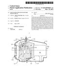
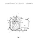
[0018] FIG. 1 is a schematic longitudinal sectional view of a multi-stage pump including one example of a reverse bypass circuit, according to the present invention;
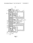
[0019] FIG. 2 is a schematic longitudinal sectional view of a pump head assembly of a multi-stage type of scroll pump having a reverse bypass circuit, according to the present invention;
[0020] FIG. 3A is a enlarged view of part of the pump head assembly of the multi-stage type of scroll pump of FIG. 2;
[0021] FIG. 3B is a enlarged view of another part of the pump head assembly of the multi-stage type of scroll pump of FIG. 2;
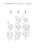
[0022] FIG. 4A is a schematic diagram of the layout of a reverse fluid bypass circuit of a two stage pump, according to the present invention;
[0023] FIG. 4B is a schematic diagram of the layout of a reverse fluid bypass circuit of a three stage pump, according to the present invention;
[0024] FIG. 4C is a schematic diagram of the layout of a reverse fluid bypass circuit of another three stage pump, according to the present invention;
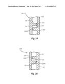
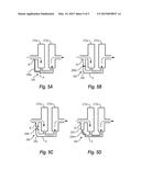
[0025] FIG. 5A is a schematic diagram of a portion of a multi-stage pump having another version of a reverse fluid bypass circuit according to the present invention;
[0026] FIG. 5B is a schematic diagram of a portion of a multi-stage pump having still another version of a reverse fluid bypass circuit according to the present invention;
[0027] FIG. 5C is a schematic diagram of a portion of a multi-stage pump having still another version of a reverse fluid bypass circuit according to the present invention; and
[0028] FIG. 5D is a schematic diagram of a portion of a multi-stage pump having yet another version of a reverse fluid bypass circuit according to the present invention.
DETAILED DESCRIPTION OF THE PREFERRED EMBODIMENTS
[0029] Various embodiments and examples of embodiments of the inventive concept will be described more fully hereinafter with reference to the accompanying drawings. In the drawings, the sizes and relative sizes of elements may be exaggerated for clarity. Likewise, the shapes of elements may be exaggerated and/or simplified for clarity and ease of understanding. Also, like numerals and reference characters are used to designate like elements throughout the drawings.
[0030] Furthermore, terminology used herein for the purpose of describing particular examples or embodiments of the inventive concept is to be taken in context. For example, the terms "comprises" or "comprising" when used in this specification indicates the presence of stated features or processes but does not preclude the presence of additional features or processes. The term "pump" may refer to apparatus that drives, or raises or decreases the pressure of a fluid, etc. The term "upstream stage" as used in connection with the compression mechanism of the pump will refer to any compression stage of the pump that is upstream of at least one other compression stage of the pump with respect to the direction of flow of fluid through the compression mechanism, i.e., the term "upstream stage" may not necessarily refer to the first stage of the compression mechanism if the pump has three or more compression stages. Likewise, the term "downstream stage" will refer to any compression stage of the pump that is downstream of at least one other stage. Therefore, unless otherwise stated, the terms "upstream" and "downstream" stages when used together will not imply that the stages are directly in series.
[0031] Referring now to FIG. 1, a multi-stage pump 1 to which the present invention can be applied generally includes a housing 100, and a pump head assembly 200, and a pump motor 300 disposed in the housing 100. The pump may also include a cooling fan 400 for cooling the pump head assembly 200 and/or the pump motor 300. In this example, the housing 100 defines an air inlet 100A and an air outlet 100B at opposite ends thereof, respectively, and the cooling fan 400 is provided in the air inlet 100A to force cooling air through the housing and out the air outlet 100B.
[0032] The housing 100 may also include a cowling 110 that covers the pump head assembly 200 and pump motor 300, and a base 120 that supports the pump head assembly 200 and pump motor 300. The cowling 110 may be of one or more parts and is detachably connected to the base 120 such that the cowling 110 can be removed from the base 120 to access the pump head assembly 200 for maintenance, repairs, etc.
[0033] The scroll vacuum pump 1 also has an inlet portion having a pump inlet 140 and constituting a low pressure side (e.g., a vacuum side) of the pump where fluid is drawn into the pump, and an exhaust portion having a pump outlet 150 and constituting a compression side where fluid is discharged from the pump at pressure greater than that of the fluid at the low pressure side. The pump head assembly 200 also has an inlet opening 260 at the inlet side of the pump, and a compression mechanism 270 that compresses the fluid, and an exhaust opening 280. The inlet opening 200 connects the inlet 140 of the pump to the compression mechanism 270 of the pump. The exhaust opening 280 connects the compression mechanism 270 of the pump to the pump outlet 150.
[0034] The compression mechanism 270 has a plurality of compression stages, including at least two compression stages disposed in series with respect to the direction of flow of fluid along a flow path defined by the pump. Each of the compression stages has an ingress through which the fluid enters the stage and an egress through which the fluid exits the stage. In the example shown FIG. 1, the pump I is a two stage pump having an upstream compression stage 270a and a downstream compression stage 270b. The flow path, as shown by the solid line with arrow heads, extends between the pump inlet 140 and the upstream compression stage 270a, between the egress of the upstream one of the compression stages 270a and the ingress of a downstream compression stage 270b, and between the egress of the downstream compression stage 270b and the pump outlet 150.
[0035] The pump 1 also has a reverse fluid bypass circuit 290 integrated with the pump head assembly 200. The reverse fluid bypass circuit 290 defines a fluid passageway 295 discrete from the flow path and connected to the flow path at a first location `A` between the egress of one (an upstream) compression stage 270a and the ingress of the next downstream compression stage 270b, and at a second location `B` upstream of the ingress of the one (upstream) compression stage 270a. The reverse fluid bypass circuit 290 also has fluid flow control means 299. The reverse fluid bypass circuit 290 will be described in more detail below.
[0036] First, however, an example of the pump head assembly 200 of a multi-stage scroll type of pump according to the present invention will be described with reference to FIG. 2
[0037] The pump head assembly 200 includes a frame 210, an inner (first) stationary plate scroll 220A, an orbiting plate scroll 230, an outer (second) stationary plate scroll 220B, an eccentric drive mechanism 240 driven as a result of a rotary output by the motor 300, a tubular member 250 and fasteners (not shown) fixing the stationary plate scrolls 220A and 220B to the frame 210 and the tubular member 250 to both the frame 210 and the orbiting plate scroll 230. As shown in the figure, the outer stationary plate scroll 220B may be fixed to the frame 210 through the intermediary of the inner stationary plate scroll 220A.
[0038] The inner stationary plate scroll 220A includes a first stationary scroll blade 221 of the pump and a first stationary plate 222 having an outer (front) side and an inner (back) side. The first stationary scroll blade 221 projects axially (parallel to a longitudinal axis of the pump) in a first direction from the outer side of the first stationary plate 222. The outer stationary plate scroll 220B includes a second stationary scroll blade 223 of the pump and a second stationary plate 224 having an outer (back) side and an inner (front) side. The second stationary scroll blade 223 projects axially in a second direction, opposite the first direction, from the inner side of the second stationary plate 224.
[0039] The orbiting plate scroll 230 is interposed between the inner and outer stationary plate scrolls 220A, 220B in the axial direction of the pump and is coupled to the eccentric drive mechanism 240 so as to be driven by the eccentric drive mechanism 240 in an orbit about the longitudinal axis of the pump. The orbiting plate scroll 230 includes an orbiting plate 231 having an outer side and an inner side, a first orbiting scroll blade 232 projecting axially in the second direction from the inner side of the orbiting plate 231, and a second orbiting scroll blade 233 projecting axially in the first direction from the outer side of the orbiting plate 231. The first orbiting scroll blade 232 is juxtaposed with the first stationary scroll blade 221 in the radial direction of the pump such that the first stationary scroll blade 221 and the first orbiting scroll blade 232 are nested, The second orbiting scroll blade 233 is juxtaposed with the second stationary scroll blade 223 of the pump in the radial direction of the pump such that the second stationary scroll blade 223 and the second orbiting scroll blade 233 are nested. In these respects, the stationary and orbiting scroll blades 223, 233 and 221, 232 are nested with a clearance and predetermined relative angular positioning such that a pocket for pockets) is delimited by and between the nested scroll blades.
[0040] The eccentric drive mechanism 240 includes a drive shaft and bearings 246. In this example, the drive shaft is a crank shaft having a main portion 242 connected to and rotated by the motor 300 about the longitudinal axis of the pump 100, and a crank 243 whose central longitudinal axis is offset in a radial direction from the longitudinal axis. The bearings 246 may comprise a plurality of sets of rolling elements.
[0041] Also, in this example, the main portion 242 of the crank shaft is supported by the frame 210 via one or more sets of the bearings 246 so as to be rotatable relative to the frame 210. The orbiting plate scroll 230 is mounted to the crank 243 via another set or sets of the bearings 246. Thus, the orbiting plate scroll 230 is carried by crank 243 so as to orbit about the longitudinal axis of the pump when the main shaft 242 is rotated by the motor 300, and the orbiting plate scroll 230 is supported by the crank 243 so as to be rotatable about the central longitudinal axis of the crank 243.
[0042] The volume of the pocket(s) delimited by the sets of nested scroll blades 221, 232 and 223, 233 is varied as the orbiting scroll blades 232, 233 move relative to the stationary scroll blades 221, 223, respectively. The motion of the orbiting scroll blades 232, 233 also causes the pocket(s) defined between the sets of nested scroll blades 221, 232 and 223, 233 to move within the pump head assembly 200 such that the pocket(s) is/are selectively placed in open communication with the pump inlet (via inlet opening 260) and the pump outlet (via exhaust opening 280). As a result, fluid is drawn along a flow path extending through the pump head assembly 200 as indicated by the arrows in the figure.
[0043] In this example, there are at least two compression stages where pumping occurs. For example, a downstream compression stage of the pump, corresponding to stage 270b in FIG. 1, may be defined between the orbiting plane scroll 230 and the inner stationary plate scroll 220A. The upstream compression stage of the pump, corresponding to compression stage 270a in FIG. 1, may be defined between the orbiting plate scroll 230 and the outer stationary plate scroll 220B.
[0044] Alternatively, the same pump may be configured as a three stage pump. For example, an upstream (or first) compression stage of the pump and an intermediate (or second) compression stage may be defined between the orbiting plate scroll 230 and the outer stationary plate scroll 220B. In this respect, reference may be made to the aforementioned U.S. Pat. No. 6,884,047 showing the provision of two stages between an orbiting plate scroll and a stationary plate scroll. In the first stage, the fluid is pumped by the action of the radially outer parts of the stationary y and orbiting scroll blades. In the second stage, the fluid is pumped by the action of the radially inner parts of the stationary and orbiting scroll blades. The radially inner parts of the stationary and orbiting scroll blades have heights that are less than those of radially outer parts of the stationary and orbiting scroll blades. Thus, the first stage has an axial depth that s greater than that of the second stage.
[0045] On the other hand, a downstream (or third) compression stage of the pump may be defined between the orbiting plate scroll 230 and the inner stationary plate scroll 220A. In this downstream compression stage, therefore, the fluid is pumped by the action of the stationary scroll blade 221 of the inner stationary plate scroll 220A and the first orbiting scroll blade 232 of the orbiting plate scroll 230.
[0046] Referring still to FIG. 2, the tubular member 250 has a first end at which it is fixed to the orbiting plate scroll 230, and a second end at which it is fixed to the frame 210. The tubular member 250 also extends around a portion of the crank shaft 243 and the bearings 246 of the eccentric drive mechanism 240. In this way, the tubular member 250 may also seal the bearings 246 and bearing surfaces. Accordingly, lubricant employed by the bearings 246 and/or particulate matter generated by the bearings surfaces can be prevented from passing into the flow path. The tubular member 250 is radially flexible enough to allow the first end thereof to follow along with the orbiting plate scroll 230 while the second end thereof remains fixed to the frame 210.
[0047] In the illustrated example, the tubular member 250 is a metallic bellows whose torsional stiffness prevents the first end thereof from rotating significantly about the central longitudinal axis of the bellows, i.e., from rotating significantly in its circumferential direction, while the second end of the bellows remains fixed to the frame 210. Accordingly, the metallic bellows 250 may provide the angular synchronization between the stationary scroll blades 221 and 223 and the first and second orbiting scroll blades 232 and 233, respectively, during the operation of the pump.
[0048] In addition, and although not shown in FIG. 2 for the sake of simplicity, the scroll pump is a dry scroll pump including tip seals each seated in a groove extending in and along the length of the tip (axial end) of a respective one of the scroll blades.
[0049] FIG. 3A shows the tip seals 220AS, 230S associated with the first stationary plate scroll 220A and the orbiting plate scroll 230, respectively. FIG. 3B shows the tip seals 220BS associated with the second stationary plate scroll 220B and the orbiting plate scroll 230, respectively. Each tip seal in this example is a plastic member interposed between the tip of the scroll blade 221, 232 of one of the first stationary and orbiting plate scrolls 220A, 230 and the plate 231, 222 of the other of the first stationary and orbiting plate scrolls 220A, 230.
[0050] The multi-stage scroll type of pump also has a reverse fluid bypass circuit corresponding to reverse fluid bypass circuit 299 shown in FIG. 1. The reverse fluid bypass circuit functions as follows. Here, reference will be made to the pump 1 of FIG. 1.
[0051] In general, the reverse bypass fluid circuit 290 circulates fluid flowing along the leg of the flow path directly connecting first and second ones of the compression stages back upstream of the ingress of the first of the compression stages when the pressure difference of the fluid between the compression stages (referred to as the inter-stage pressure) and the pressure at the ingress of the first stage exceeds a predetermined value. In the case of the two stage pump 1 of FIG. 1, for example, the reverse bypass fluid circuit 290 circulates fluid flowing along the leg of the flow path connecting the first and second compression stages 270a, 270h back upstream of the ingress of the first compression stage 270a and therefore, essentially back to the inlet 140 of the pump, when the inter-stage pressure compared to the inlet pressure is higher by a predetermined amount, e.g., is higher by ˜1-2 psi.
[0052] To this end, the fluid flow control means 299 may comprise a valve, such as a spring-loaded check valve whose cracking pressure is set to open When the inter-stage pressure is higher than the inlet pressure by the predetermined amount. In the example given above in which the inter-stage pressure is ˜1-2 psi higher than the inlet pressure, the cracking pressure of the check valve may be 1-1.5 psi. Other types of valves, such as pneumatically- or solenoid-operated valves may be employed instead. In these cases, the reverse fluid bypass circuit may also include one or more pressure sensors connected to the fluid passageway 295 and operatively connected to the valve so as to open the valve when a predetermined pressure or pressure difference is sensed in passageway 295.
[0053] This provides the following advantages. Maximum power consumption in both the first and second stages 270a, 270b is constrained by the operation of the reverse fluid bypass circuit 290. Constraining the maximum power consumption in the first stage 270a, in addition to in the second stage 270b, results in a dramatic reduction in driving torque, allowing the pump 1 to start as well as protecting the bearings and motor 300 from excessive loads.
[0054] Secondly, a tip seal that is not spring loaded, as shown in and described with reference to FIGS. 2, 3A and 3B, must remain "energized" meaning that it must remain in engagement with the opposing plate to provide a sufficient seal even, for example, when the tip seal Nears by a certain amount during use. If the tip seals of a second and any additional downstream compression stages are not "energized", the large pressure differential across the first stage combined with a relatively large first stage displacement could potential overload the motor. This, in turn, could prevent the pump from starting or damage other components in the pump such as bearings.
[0055] In order to energize each of the tip seals, a pressure differential across the tip seal is typically required to force the tip seal against the opposing plate which will then provide the required sealing. However, in order to generate the necessary pressure to "energize" the tip seals, the tip seals must first move forward against the opposing plate to create a sufficient seal. Accordingly, it is possible for the tip seals to not "energize" properly when the pump is starting, especially if the pump is equipped with a forward fluid bypass circuit which prevents pressure from being developed in the space between the first and second stages that would otherwise serve to energize the tip seals.
[0056] By circulating the fluid back upstream of the ingress of an upstream compression stage when a certain inter-stage pressure differential exists between the ingress of the upstream compression stage and the ingress of the next downstream compression stage, the reverse fluid bypass circuit 290 of the present invention helps ensure that the tip seals of the next downstream compression stage and those of any additional downstream compression stages are "energized".
[0057] FIGS. 4A, 4B and 4C illustrate different layouts of the reverse fluid bypass circuit 290. Any of these layouts may be applied to the multi-stage scroll type of pump shown in and described with reference to FIG. 2, as well as to any other type of multi-stage positive displacement pump.
[0058] FIG. 4A shows a two stage pump in which the compression mechanism consists of a 1st (upstream) compression stage and a 2nd (downstream) compression stage. Here, the inter-stage pressure differential that the reverse fluid bypass circuit 290 regulates is that between the ingress of the 1st stage and ingress of the 2nd stage.
[0059] FIG. 4B shows a three stage pump in which the 1st, 2nd, and 3rd compression stages are connected in series by a contiguous flow path of the pump extending from the pump inlet to the pump outlet. In this example, the 2nd compression stage is an upstream compression stage, the 3rd compression stage is the next downstream compression stage and the reverse fluid bypass circuit circulates the fluid back to location B upstream of the ingress of the 1st compression stage and hence, upstream of the ingress of the 2nd compression stage. Here, the inter-stage pressure differential that the reverse fluid bypass 290 regulates is that between the egress of the 2nd stage and the ingress of the 1st stage. That is, this example shows that the upstream compression stage does not have to be the first compression stage along the flow path.
[0060] FIG. 4C shows a three stage pump in which the 1st, 2nd, and 3rd compression stages have a parallel arrangement. In this case, a contiguous flow path of the pump extends from the pump inlet directly to the 2nd compression stage, from the 2nd compression to the 3rd compression stage, and from the 3rd compression stage to the pump outlet. In this example, the 2nd compression stage is an upstream compression stage, the 3rd compression stage is the next downstream compression stage and the reverse fluid bypass circuit circulates the fluid back to location B upstream of the ingress of the 2nd compression stage. Here, the inter-stage pressure differential that the reverse fluid bypass circuit 290 regulates is between the egress and ingress of the 2nd stage.
[0061] Of course, these layouts may be extended to apply to multi-stage pumps having more than three compression stages.
[0062] Furthermore, although the reverse fluid bypass circuit 290 has been described above as having flow control means in the form of a valve such as a spring-loaded check valve, FIGS. 5A-5D show alternative forms of the flow control means.
[0063] FIG. 5A shows the reverse fluid bypass circuit 290 as including a capillary tube 299a as flow control means.
[0064] FIG. 5B shows the reverse fluid bypass circuit 290 as including an orifice 299b disposed in-line with the fluid passageway 295.
[0065] FIG. 5C shows the reverse fluid bypass circuit 290 as including a flexible tube which collapses when the pressure inside the tube is less than the pressure outside the tube by a certain amount. Atmospheric or another reference pressure provides the force to collapse the flexible tube when the pressure inside drops below a predetermined value.
[0066] FIG. 5D shows an example of fluid flow control means for restricting the flow of fluid while the fluid is in its transitional or molecular flow regime, while allowing the flow of fluid while the fluid is in its viscous flow regime. In this example, the reverse fluid bypass circuit 290 includes a labyrinth seal 299d. However, other fluid flow control means may be used to restrict flow in the transitional or molecular regime, while allowing flow in the viscous regime.
[0067] Finally, embodiments of the inventive concept and examples thereof have been described above in detail. The inventive concept may, however, be embodied in many different forms and should not be construed as being limited to the embodiments described above. Rather, these embodiments were described so that this disclosure is thorough and complete, and fully conveys the inventive concept to those skilled in the art. Thus, the true spirit and scope of the inventive concept is not limited by the embodiment and examples described above but by the following claims.
User Contributions:
Comment about this patent or add new information about this topic:
Images included with this patent application:
 |  |
 |  |
 |  |
| Similar patent applications: | |
| Date | Title |
|---|---|
| 2015-03-19 | Air treatment chemical dispenser having angled dispersion of chemicals |
| 2015-03-19 | Electric pump and cleaning device for on-vehicle optical sensor |
| 2015-03-19 | Compressor, air conditioner system comprising the compressor and heat pump water heater system |
| 2015-01-29 | Multiple parts reed valve and method of manufacturing |
| 2015-02-05 | Solid state fluid level sensor |
| New patent applications in this class: | |
| Date | Title |
|---|---|
| 2015-10-29 | Electric motor-driven compressor having bi-directional liquid coolant passage |
| 2015-05-14 | Pump device with a vacuum pump and a lubrication pump |
| 2015-04-30 | Compressor thrust bearing surge protection |
| 2015-04-16 | Internal-driven compressor having a powered compressor rotor |
| 2014-10-02 | Actuating device for an adjustable convertible top system of a motor vehicle |
| New patent applications from these inventors: | |
| Date | Title |
|---|---|
| 2022-07-14 | Double sided oil film thrust bearing in a scroll pump |
| 2021-11-11 | Air gap magnetic coupling with counterbalanced force |
| 2015-07-02 | Vacuum scroll pump having pressure-balanced orbiting plate scroll |
| 2015-06-11 | Scroll pump having axially compliant spring element |
| 2015-06-11 | Scroll pump having axially compliant spring element |
| Top Inventors for class "Pumps" | |
| Rank | Inventor's name |
|---|---|
| 1 | Masaki Ota |
| 2 | Ken Suitou |
| 3 | Alex Horng |
| 4 | Yusuke Yamazaki |
| 5 | Lars Hoffmann Berthelsen |