Patent application title: HIGH SPEED HIGH RESOLUTION HETERODYNE INTERFEROMETRIC METHOD AND SYSTEM
Inventors:
Jiubin Tan (Harbin, CN)
Pengcheng Hu (Harbin, CN)
Xiaofei Diao (Harbin, CN)
IPC8 Class: AG01B902FI
USPC Class:
356487
Class name: For dimensional measurement (e.g., thickness gap, alignment, profile) displacement or distance polarization
Publication date: 2015-02-12
Patent application number: 20150043004
Abstract:
A high speed high resolution heterodyne interferometric method and system
are provided. The invention uses two spatially separated beams with
slightly different frequencies and has two measurement signals with
opposite Doppler shift. The switching circuit selects one of the two
measurement signals for displacement measurement according to the
direction and speed of the target movement. In this invention, the
measurement is insensitive to the thermal variation; the periodic
nonlinearity is essentially eliminated by using two spatially separated
beams; the measurable target speed of the interferometer is no longer
limited by the beat frequency of the laser source.Claims:
1. A high speed high resolution heterodyne interferometric method, which
comprise the steps of: (a) providing two parallel laser beams which are
linear polarized laser beam having a 45.degree. angle from the horizontal
direction and with different frequencies f1 and f2; (b)
detecting one portion of each of the two laser beams by a photodiode and
the result is then converted to a reference signal having a frequency
(fb), where fb=f1-f2; (c) dividing the other portion
of each of the two laser beams into a reference beam and a measurement
beam by a polarizing beam splitter; (d) directing the two reference beams
with different frequencies f1 and f2 respectively through a
reference prism reflector to a reference reflector by means of which they
are reflected back to the polarizing beam splitter; (e) directing the two
measurement beams with different frequencies f1 and f2
respectively through a quarter wave plate to a plane mirror by which they
are reflected back through the quarter wave plate to the polarizing beam
splitter by which they are reflected to the measurement reflector and by
the measurement reflector to the polarizing beam splitter again, at the
polarizing beam splitter they are reflected to pass through the quarter
wave plate and are then reflected by the plane mirror so as to further
pass through the quarter wave plate and are then pass through the
polarizing beam splitter; (f) adjusting the reference reflector and the
measurement reflector such that the measurement beam with frequency
f1 interferes with the reference beam with frequency f2 whereby
a first measurement signal Im1 of frequency fb+Δf is
generated; and that the measurement beam with frequency f2
interferes with the reference beam with frequency f1, whereby a
second measurement signal Im2 of frequency fb-.DELTA.f is
generated; (g) detecting the two measurement signals at two photodiodes
respectively and the respective results are then transferred to a first
phasemeter for processing the first measurement signal Im1 and to a
second phasemeter for processing the second measurement signal Im2
respectively; (h) selecting between the first phasemeter and the second
phasemeter by a switching circuit according to the direction and speed of
the movement of the plane mirror; (i) calculating the displacement of the
measuring subject according to the output of the selected phasemeter.
2. The method as claimed in claim 1, wherein the first phasemeter is selected when the plane mirror moves towards the polarizing beam splitter at a speed which exceeds a first preset speed V1, and the second phasemeter is selected when the plane mirror moves away from the polarizing beam splitter at a speed which exceeds a second preset speed V.sub.2.
3. The method as claimed in claim 1, wherein the two laser beams are provided by a single laser source.
4. A high speed high resolution heterodyne interferometric system, which comprises: a frequency stabilized laser (1) provided as a light source of the heterodyne interferometric system; a polarizing beam splitter (2) provided to divide the laser beams from said stabilized laser (1); a right angle prism (6) provided to reflect the laser beams reflected by said polarizing beam splitter (2); a reference reflector (7) provided to reflect the laser beams from said right angle prism (6); a quarter wave plate (4) provided to change the polarization of the laser beams transmitted by said polarizing beam splitter (2); a plane mirror (5) provided to reflect the laser beams from the said quarter wave plate (4); a measurement reflector (3) provided to reflect the laser beams reflect by said polarizing beam splitter (2) and placed on the opposite direction of said polarizing beam splitter (2) with respect to right angle prism (6); a first photodiode (8) provided to detect one the measurement beam of the heterodyne interferometric system; a second photodiode (9) provided to detect the other the measurement beam of the heterodyne interferometric system; a first phasemeter (10) provided to measure the measurement signal from said first photodiode (8) and the reference signal from said stabilized laser (1); a second phasemeter (11) provided to measure the measurement signal from said second photodiode (9) and the reference signal from said stabilized laser (1); a switching circuit (12) provided to measure the signal from said first phasemeter (10) or said second phasemeter (11); and a measurement circuit (13) provided to process the signal from said switching circuit (12).
5. The system as claimed in claim 4, wherein said reference reflector (7) is a retroreflector and said measurement reflector (3) is a right angle prism.
6. The system as claimed in claim 4, wherein said reference reflector (7) is a right angle prism and said measurement reflector (3) is a retroreflector.
7. The system as claimed in claim 4, wherein said reference reflector (7) is composed of two retroreflectors and said measurement reflector (3) is a retroreflector.
8. The system as claimed in claim 4, wherein said reference reflector (7) is a retroreflector and said measurement reflector (3) is composed of two retroreflectors.
9. The system as claimed in claim 4, wherein the side length of said right angle prism (6) equals to the side length of the polarizing beam splitter (2).
Description:
BACKGROUND OF THE INVENTION
[0001] 1. Technical Field of the Invention
[0002] The present invention relates to a high speed high resolution heterodyne interferometric method and system, which can be used for measuring a high speed target using a laser source with low beat frequency.
[0003] 2. Technical Background
[0004] The heterodyne interferometer has been widely used in many precision machines and calibration services due to its large measuring range, high signal-to-noise ratio and high measurement precision. Nowadays, high resolution, high speed and high accuracy measurements are required for many applications in order to produce small features with competitive production throughput. This initiates an improvement of the performance of the heterodyne interferometer to satisfy industrial demands.
[0005] The periodic nonlinearity caused by frequency and polarization mixing effects limits the accuracy and resolution of a heterodyne interferometer. A lot of research has been done to reduce the periodic errors, but the traditional heterodyne interferometer can not eliminate the frequency and polarization mixing effects, which make it difficult to realized high resolution and high precision displacement measurement.
[0006] T. L. Schmitz and J. F. Beckwith proposed a heterodyne interferometer with a acousto-optic modulator as a beam splitter. The measurement beam and the reference beam are spatially separated, which can reduce the frequency and polarization mixing effects. Therefore, the periodic nonlinearity is reduced; the precision and resolution are also improved. But its specific and complicated configuration limits the typically possible applications for measuring displacement.
[0007] Ki-Nam Joo, Jonathan D. Ellis, et al. proposed a simple heterodyne interferometer, which has spatially separated reference beam and measurement beam. This interferometer can eliminate the frequency and polarization mixing effects. The periodic nonlinearity is also eliminated and the precision is improved. Its configuration is simple which make it applicable to precision industrial engineering. But the measurement speed is limited by the beat frequency of laser source.
[0008] In conclusion, the existing methods and apparatuses described above isn't suitable for high resolution, high speed and high accuracy measurements.
SUMMARY OF THE INVENTION
[0009] One purpose of this invention is to provide a high speed high resolution heterodyne interferometric method and system, which is suitable for high resolution, high speed and high accuracy measurements.
[0010] According to one aspect of the invention, a high speed high resolution heterodyne interferometric method is proposed which comprise the steps of:
[0011] (a) providing two parallel laser beams which are linear polarized laser beam having a 45° angle from the horizontal direction and with different frequencies f1 and f2;
[0012] (b) detecting one portion of each of the two laser beams by a photodiode and the result is then converted to a reference signal having a frequency (fb), where fb=f1-f2;
[0013] (c) dividing the other portion of each of the two laser beams into a reference beam and a measurement beam by a polarizing beam splitter;
[0014] (d) directing the two reference beams with different frequencies f1 and f2 respectively through a reference prism reflector to a reference reflector by means of which they are reflected back to the polarizing beam splitter;
[0015] (e) directing the two measurement beams with different frequencies f1 and f2 respectively through a quarter wave plate to a plane mirror by which they are reflected back through the quarter wave plate to the polarizing beam splitter by which they are reflected to the measurement reflector and by the measurement reflector to the polarizing beam splitter again, at the polarizing beam splitter they are reflected to pass through the quarter wave plate and are then reflected by the plane mirror so as to further pass through the quarter wave plate and are then pass through the polarizing beam splitter;
[0016] (f) adjusting the reference reflector and the measurement reflector such that the measurement beam with frequency f1 interferes with the reference beam with frequency f2 whereby a first measurement signal Im1 of frequency fb+Δf is generated; and that the measurement beam with frequency f2 interferes with the reference beam with frequency f1, whereby a second measurement signal Im2 of frequency fb-Δf is generated;
[0017] (g) detecting the two measurement signals at two photodiodes respectively and the respective results are then transferred to a first phasemeter for processing the first measurement signal Im1 and to a second phasemeter for processing the second measurement signal Im2 respectively;
[0018] (h) selecting between the first phasemeter and the second phasemeter by a switching circuit according to the direction and speed of the movement of the plane mirror;
[0019] (i) calculating the displacement of the measuring subject according to the output of the selected phasemeter.
[0020] The first phasemeter is selected when the plane mirror moves towards the polarizing beam splitter at a speed which exceeds a first preset speed V1, and the second phasemeter is selected when the plane mirror moves away from the polarizing beam splitter at a speed which exceeds a second preset speed V2.
[0021] The two laser beams are provided by a single laser source.
[0022] According to a second aspect the present invention, a high speed high resolution heterodyne interferometric system is proposed. In this system, a frequency stabilized laser provided as a light source of the heterodyne interferometric system; a polarizing beam splitter provided to divide the laser beams from said frequency stabilized laser; a right angle prism provided to reflect the laser beams reflected by said polarizing beam splitter; a reference reflector provided to reflect the laser beams from said right angle prism; a quarter wave plate provided to change the polarization of the laser beams transmitted by said polarizing beam splitter; a plane mirror provided to reflect the laser beams from the said quarter wave plate; a measurement reflector provided to reflect the laser beams reflect by said polarizing beam splitter and placed on the opposite direction of said polarizing beam splitter with respect to right angle prism; a first photodiode provided to detect one the measurement beam of the heterodyne interferometric system; a second photodiode provided to detect the other the measurement beam of the heterodyne interferometric system; a first phasemeter provided to measure the measurement signal from said first photodiode and the reference signal from said frequency stabilized laser; a second phasemeter provided to measure the measurement signal from said second photodiode and the reference signal from said frequency stabilized laser; a switching circuit provided to measure the signal from said first phasemeter or said second phasemeter; a measurement circuit provided to process the signal from said switching circuit.
[0023] Said reference reflector is a retroreflector and said measurement reflector is a right angle prism.
[0024] Said reference reflector is a right angle prism and said measurement reflector is a retroreflector.
[0025] Said reference reflector is composed of two retroreflectors and said measurement reflector is a retroreflector.
[0026] Said reference reflector is a retroreflector and said measurement reflector is composed of two retroreflectors.
[0027] The side length of said right angle prism equals to the side length of the polarizing beam splitter.
[0028] The features and advantages of this invention are shown as detailed below:
[0029] (1) The measurement beam and the reference beam in this method and system are spatially separated, which eliminates the frequency and polarization mixing effects. As a result, the periodic nonlinearity is eliminated.
[0030] (2) The measurement signals have opposite Doppler shift for the same target movement. One of the two measurement signals is used selectively according to the direction of the target movement, so that the Doppler shift always increases the beat frequency of the selected signal. As a result, the interferometer can measure a high speed target by using a laser source with low beat frequency.
[0031] (3) The measurement circuit can produce high resolution measurements with an ordinary electric clock signal, which make the measurement circuit simple and easy to realize with low cost components.
BRIEF DESCRIPTION OF THE DRAWINGS
[0032] IN THE DRAWINGS,
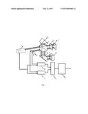
[0033] FIG. 1: construction of the high speed high resolution heterodyne interferometric system proposed in preferred embodiment;
[0034] Specification of piece numbers in FIG. 1: 1 frequency stabilized laser, 2 polarizing beam splitter, 3 measurement reflector, 4 quarter wave plate, 5 plane mirror, 6 right angle prism, 7 reference reflector, 8 photodiode A, 9 photodiode B, 10 phasemeter A, 11 phasemeter B, 12 switching circuit, 13 measurement circuit.
PREFERRED EMBODIMENTS OF THE INVENTION
[0035] As shown in FIG. 1, a high speed high resolution heterodyne interferometric system, which comprises: a frequency stabilized laser 1 provided as a light source of the heterodyne interferometric system; a polarizing beam splitter 2 provided to divide the laser beams from said frequency stabilized laser 1; a right angle prism 6 provided to reflect the laser beams reflected by said polarizing beam splitter 2; a reference reflector 7 provided to reflect the laser beams from said right angle prism 6; a quarter wave plate 4 provided to change the polarization of the laser beams transmitted by said polarizing beam splitter 2; a plane mirror 5 provided to reflect the laser beams from the said quarter wave plate 4; a measurement reflector 3 provided to reflect the laser beams reflect by said polarizing beam splitter 2 and placed on the opposite direction of said polarizing beam splitter 2 with respect to right angle prism 6; a photodiode A 8 provided to detect one the measurement beam of the the heterodyne interferometric system; a photodiode B 9 provided to detect the other the measurement beam of the heterodyne interferometric system; a phasemeter A 10 provided to measure the measurement signal from said photodiode A 8 and the reference signal from said frequency stabilized laser 1; a phasemeter B 11 provided to measure the measurement signal from said photodiode B 9 and the reference signal from said frequency stabilized laser 1; a switching circuit 12 provided to measure the signal from said phasemeter A 10 or said phasemeter B 11; a measurement circuit 13 provided to process the signal from said switching circuit 12.
[0036] A high speed high resolution heterodyne interferometric method, which comprise the steps of:
[0037] (a) providing two parallel laser beams which are linear polarized laser beam having a 45° angle from the horizontal direction and with different frequencies f1 and f2;
[0038] (b) detecting one portion of each of the two laser beams by a photodiode and the result is then converted to a reference signal having a frequency (fb), where fb=f1-f2;
[0039] (c) dividing the other portion of each of the two laser beams into a reference beam and a measurement beam by a polarizing beam splitter;
[0040] (d) directing the two reference beams with different frequencies f1 and f2 respectively through a reference prism reflector to a reference reflector by means of which they are reflected back to the polarizing beam splitter;
[0041] (e) directing the two measurement beams with different frequencies f1 and f2 respectively through a quarter wave plate to a plane mirror by which they are reflected back through the quarter wave plate to the polarizing beam splitter by which they are reflected to the measurement reflector and by the measurement reflector to the polarizing beam splitter again, at the polarizing beam splitter they are reflected to pass through the quarter wave plate and are then reflected by the plane mirror so as to further pass through the quarter wave plate and are then pass through the polarizing beam splitter;
[0042] (f) adjusting the reference reflector and the measurement reflector such that the measurement beam with frequency f1 interferes with the reference beam with frequency f2 whereby a first measurement signal Im1 of frequency fb+Δf is generated; and that the measurement beam with frequency f2 interferes with the reference beam with frequency f1, whereby a second measurement signal Im2 of frequency fb-Δf is generated;
[0043] (g) detecting the two measurement signals at two photodiodes respectively and the respective results are then transferred to a phasemeter A for processing the first measurement signal Im1 and to a phasemeter B for processing the second measurement signal Im2 respectively;
[0044] (h) selecting between the phasemeter A and the phasemeter B by a switching circuit according to the direction and speed of the movement of the plane mirror, said switching circuit selects phasemeter B when the plane mirror moves away from the polarizing beam splitter and the speed exceeds a preset value V1, said switching circuit selects phasemeter A when the plane mirror moves close to the polarizing beam splitter and the speed exceeds a preset value V2, the two phasemeters have overlapping detection range, the switching circuit doesn't operate in the common detection range to prevent the switching chattering phenomenon;
[0045] (i) calculating the displacement of the measuring subject according to the output of the selected phasemeter.
User Contributions:
Comment about this patent or add new information about this topic:
Images included with this patent application:
 |  |
| Similar patent applications: | |
| Date | Title |
|---|---|
| 2015-02-19 | Grazing-incidence interferometer with dual-side measurement capability |
| 2015-02-19 | Automated position locator for a height sensor in a dispensing system |
| 2015-02-19 | Integrated optical illumination reference source |
| 2015-02-19 | Portable interferometric device |
| 2015-02-12 | Virtual laser projection system and method |
| New patent applications in this class: | |
| Date | Title |
|---|---|
| 2015-11-26 | Heterodyne grating interferometer displacement measurement system |
| 2015-02-12 | Interferometric heterodyne optical encoder system |
| 2014-08-07 | Optical position-measuring device |
| 2014-06-12 | Four-axis four-subdividing interferometer |
| 2012-10-04 | Interferometer module |
| Top Inventors for class "Optics: measuring and testing" | |
| Rank | Inventor's name |
|---|---|
| 1 | Robert E. Bridges |
| 2 | Yuta Urano |
| 3 | Glen A. Sanders |
| 4 | Zhiyong Li |
| 5 | Akira Hamamatsu |