Patent application title: DISPLACEMENT EQUALIZING HYDRAULIC TENSIONER FOR MULTI-STRAND ENDLESS CHAIN
Inventors:
Silas G. Curfman (Sunnyside, WA, US)
Robert M. Curfman (Sunnyside, WA, US)
IPC8 Class: AF16H712FI
USPC Class:
474110
Class name: Endless belt power transmission systems or components means for adjusting belt tension or for shifting belt, pulley or guide roll tension adjuster or shifter driven by electrical or fluid motor
Publication date: 2015-01-22
Patent application number: 20150024888
Abstract:
A method and apparatus for tensioning multi-strand endless chain
conveyors ensuring equal displacement and constant alignment of each
strand of endless chain. Included are a hydraulically actuated cylinder
assembly, a equalizing yoke assembly, and a guide frame assembly.
Hydraulic lines supplying fluid to the cylinder assembly have both check
valves to prevent retraction and pressure sight indicators to signal when
proper hydraulic pressure is achieved during adjustment. A common yoke
and guide track is included to maintain equal displacement of chain
strands while applying tensioning force. Also included is a guidance
apparatus that prevents seizing of components due to foreign debris and
also allows for easy removal of system for maintenance or replacement.Claims:
1. An apparatus for applying equalized tension to a multi strand endless
chain, comprising: a. a guide frame comprising: i. a fixed frame having a
plurality of elongated guide grooves oriented parallel to each other and
of equal length, ii. a removable access pad affixed over each of said
guide grooves iii. said guide grooves and said access pad(s) constitutes
a first means for forming an enclosed slide channel and a second means
for easily gaining access to interior of said slide channel; b. an
equalizing yoke comprising: i. an elongated equalizing beam having a
plurality of mounts oriented perpendicular to said equalizing beam, ii. a
plurality of displacement arms having mounts at each end and rigidly
affixed said equalizing beam and oriented perpendicular to said
equalizing beam, iii. an idler axle, having a plurality of idler
sprockets, oriented parallel to said equalizer beam and rotably mounted
to said displacement arms opposite said equalizing beam; c. a hydraulic
actuator comprising: i. a hydraulic cylinder having an extensible piston
and a check valve, said hydraulic cylinder being rigidly affixed at one
end and contiguous to said equalizing beam at the opposite end and ii. a
hydraulic source connected to said hydraulic cylinder having an inlet
port and a relief indicator iii. whereby hydraulic medium applied through
said hydraulic inlet provides a first means for displacement of said
hydraulic cylinder thereby causing said displacement arms to travel in a
slidably constrained common direction of equal displacement and a
provides a second means for said idler axle to retain its position
against the urging of the chains contiguous to it.Description:
REFERENCES
[0001] This application claims the benefit of PPA Ser. No. 61/847,958, filed Jul. 18, 2013
BACKGROUND
[0002] The present invention is in the technical field of agriculture machinery. More particularly, the present invention is in the technical field of mobile bulk material handling and transport equipment incorporating multi-strand endless chain conveyors.
[0003] Conveyor tensioning devices as found on conventional mobile bulk material transport equipment, such as manure spreaders, compost spreaders, animal feed delivery vehicles, and the like, typically are cumbersome to adjust, difficult to maintain equal displacement of chain strands, and incapable of handling the forces associated with conveyor direction reversal. Adjusting such tensioners requires multiple tools, can only be done with the vehicle(s) out of service, and cannot easily ensure equal displacement of each strand of chain. Due to this it is not uncommon for such chains to fail due to lack of, or improper, maintenance. Further, such tensioners have the limitation that they cannot withstand the high forces encountered if the direction of conveyor operation should need to be reversed.
RELEVANT PRIOR ART INCLUDES
[0004] U.S. Pat. No. 4,457,564--Tensioning device for endless chain
[0005] U.S. Pat. No. 6,322,171--Track tensioning assembly
[0006] U.S. Pat. No. 5,738,421--Hydraulic chain tensioning means for tensioning the crawler chains of crawler vehicles
[0007] U.S. Pat. No. 3,963,047--Fill and relief valve arrangement
[0008] U.S. Pat. No. 7,922,266--Chain tensioning device
[0009] U.S. Pat. No. 5,984,436--Hydraulic track tensioning circuit
[0010] U.S. Pat. No. 6,929,334--Caterpillar track tensioning management
[0011] U.S. Pat. No. 7,770,984--Track belt tensioning method
[0012] U.S. Pat. No. 4,681,376--Apparatus for tensioning a track chain of a tracklaying vehicle
[0013] U.S. Pat. No. 6,249,994--Apparatus and method for operating track tensioning assembly of a hydraulic excavator
ADVANTAGES
[0014] One advantage is that the present invention ensures equal displacement of each strand of multi-strand conveyors rather than equal force. Without ensuring an equal displacement of each strand while tensioning, other mechanisms fail to maintain the alignment and common wear necessary in multi-strand systems. Another advantage is that by incorporating a hydraulic check as a braking mechanism the present invention can withstand high forces encountered during conveyor direction reversal. Finally another advantage is by including manually operated remote application ports with visible pressure indicators operators can maintain proper tension in a manner both safer and more accurate than all other methods.
BRIEF SUMMARY OF THE INVENTION
[0015] The present invention is a hydraulically actuated chain tensioning device for multi-strand endless chain conveyors. The invention is configured to be mounted within a loop of multi-strand endless conveyor chain thus applying tension and alignment from within the loop of chain. The invention includes a single acting hydraulic cylinder which applies pressure to a common yoke and provides a hydraulic braking effect in the case of conveyor direction reversal. The invention includes a common yoke which ensures equal displacement is applied to multiple tension arms. The invention includes a free running non-seizing guide track to ensure constant alignment of common yoke and tension arms, as well as prevent seizing or freezing of tension arms within the guide track. Remote inlet ports are included. These remote inlet ports can be accessed at a safe distance away from the conveyor chain and include sight indicators that signal when proper tension is applied.
BRIEF DESCRIPTION OF THE DRAWINGS
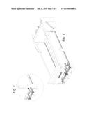
[0016] FIG. 1. FIG. 1 shows a perspective view of the present invention mounted in a possible configuration.
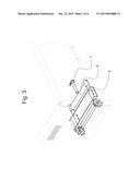
[0017] FIG. 2. FIG. 2 illustrates a perspective detail view of the present invention.
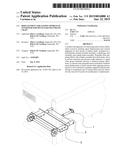
[0018] FIG. 3. FIG. 3 presents a perspective detail view of the present invention
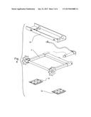
[0019] FIG. 4. FIG. 4 presents an exploded view of the present invention.
[0020] FIG. 5. Presents an exploded view of the hydraulic cylinder device of the present invention.
[0021] FIG. 6. Presents an exploded view of the common yoke device of the present invention.
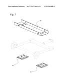
[0022] FIG. 7. Presents an exploded view of the guide track device of the present invention.
DRAWINGS--REFERENCE NUMERALS
[0023] 1--hydraulic actuator assembly
[0024] 2--equalizing yoke assembly
[0025] 3--guide frame assembly
[0026] 4--hydraulic cylinder
[0027] 5--piston wiper
[0028] 6--pressure seal
[0029] 7--piston
[0030] 8--check valve
[0031] 9--hydraulic line
[0032] 10--remote inlet port
[0033] 11--displacement arm
[0034] 12--equalizing beam
[0035] 13--idler axle
[0036] 14--guide bearing
[0037] 15--fixed frame
[0038] 16--removable access pads
DETAILED DESCRIPTION AND BEST MODE OF IMPLEMENTATION
[0039] Referring now to the invention in more detail, FIG. 1, FIG. 2, and FIG. 3 there is shown a hydraulic tensioning device being mounted within the loop of an endless chain multi-strand conveyor. Shown is a hydraulic actuator 1 applying force to a equalizing yoke assembly 2 being guided by a guide frame assembly 3 ensuring tension force is applied while maintaining an equal displacement of the displacement arms 11 and idler axle 13.
[0040] In further detail, referring to FIG. 5, the piston 7 is actuated by the application of hydraulic medium, such as hydraulic oil or grease, at remote inlet port 10 through hydraulic line 9 past check valve 8 having filled hydraulic cylinder 4. Constant pressure is maintained in hydraulic cylinder 4 by the combined operation of pressure seal 6, check valve 8, and remote inlet port 10. Over pressuring of hydraulic cylinder 4 is prevented by remote inlet port 10 relieving hydraulic pressure at a fixed desired input pressure. A braking effect, necessary to withstand conveyor direction reversal, is provided by a one-way check valve 8 having a higher fixed pressure setting than remote inlet port 10.
[0041] Referring now to FIG. 4, FIG. 5, FIG. 6, and FIG. 7 there is shown a yoke 12 fixed to multiple displacement arms 11 which support an idler axle 13. As piston 7 extends and applies force to equalizing beam 12 advancing displacement arms 11 contained in fixed frame 15 held in position by removable access pads 16. As displacement arms 11 slidably advance in fixed frame 15 misalignment is prevented by the close fit between them. As displacement arms 11 are prevented from misalignment by fixed frame 15 the idler axle 13 applies tensioning force at a uniform displacement to each strand of a multi-strand endless chain.
[0042] Referring now to FIG. 6 and FIG. 7 multiple methods for removal and service of hydraulic actuator 1 and equalizing yoke assembly 2 are provided. First, equalizing yoke assembly 2 can be disassembled and displacement arms 11 can be removed through fixed frame 15 in a direction parallel to the operating axis of piston 7. By removing check valve 8 piston 7 can be retracted into hydraulic cylinder 4 thus allowing equalizing beam 12 to be removed in a direction perpendicular to the operating axis of piston 7. Further, an alternate removal exists. By removing removable access pads 16 the entire equalizing yoke assembly 2 and hydraulic actuator 1 can be removed in a direction perpendicular to the operating axis of piston 7.
CONCLUSION
[0043] Accordingly, the reader will see that the displacement equalizing tensioning apparatus can be used to ensure and maintain alignment of all strands of a multi-strand conveyor chain. Furthermore the tensioning apparatus has the additional advantages in that:
[0044] a. it permits the withstanding of high forces due to conveyor direction reversal, thus allowing regular and repeated reversals without damaging the conveyor drives;
[0045] b. it provides a remote indication of proper tensioning force thus allowing operators to maintain a safe distance away from the tensioning apparatus;
[0046] c. it provides an easily accessible access point through track access panels for maintenance and inspection purposes;
User Contributions:
Comment about this patent or add new information about this topic:
Images included with this patent application:
 |  |
 |  |
 |  |
 |
| Similar patent applications: | |
| Date | Title |
|---|---|
| 2015-02-26 | Method for producing a link-plate chain |
| 2009-11-19 | Sealed tensioner |
| 2014-11-06 | Anti-backbend chain |
| 2014-12-04 | System and method for minimal draindown in cvt |
| 2015-03-19 | Bearing roller chain |
| New patent applications in this class: | |
| Date | Title |
|---|---|
| 2016-06-30 | Transmission system comprising an oil wet toothed belt |
| 2016-06-30 | Chain tensioner |
| 2016-06-16 | Linear derailleur mechanism |
| 2016-06-02 | Tensioner |
| 2016-05-05 | Tensioner |
| Top Inventors for class "Endless belt power transmission systems or components" | |
| Rank | Inventor's name |
|---|---|
| 1 | Yuji Kurematsu |
| 2 | Atsuhiro Emura |
| 3 | Osamu Yoshida |
| 4 | Lucian Botez |
| 5 | Bernd Hartmann |