Patent application title: LIDAR Device and Method for Clear and Degraded Environmental Viewing Conditions
Inventors:
David Ludwig (Irvine, CA, US)
David Ludwig (Irvine, CA, US)
Alan C. Rogers (Anaheim, CA, US)
Medhat Azzazy (Laguna Niguel, CA, US)
Medhat Azzazy (Laguna Niguel, CA, US)
James W. Justice (Newport Beach, CA, US)
IPC8 Class: AG01S1789FI
USPC Class:
356 401
Class name: Optics: measuring and testing range or remote distance finding with photodetection
Publication date: 2014-12-25
Patent application number: 20140375977
Abstract:
A LIDAR system that can accommodate both a clear atmosphere and be
adaptable to environments in which smoke, dust or other particulates
(i.e., a degraded environment) exist in the atmosphere around the target
is described. The system operates in two fields of regard: clear view
mode (wide field of regard) and a degraded view mode (narrow field of
regard). The wide field of regard allows the output laser energy to be
concentrated over a large number of detector pixels and thus resulting in
high scene scan rate. The narrow field of regard allows concentrating the
laser output energy on fewer pixels to compensate for the loss of laser
energy due to atmospheric degradation. The combination of the ROIC and
LIDAR modes of operation result in a system that is capable of operation
under clear and degraded environments.Claims:
1. A LIDAR system comprising many alterations and modifications may be
made by those having ordinary skill in the art without departing from the
spirit and scope of the invention. Therefore, it must be understood that
the illustrated embodiment has been set forth only for the purposes of
example and that it should not be taken as limiting the invention as
defined by any claims in any subsequent application claiming priority to
this application. for example, notwithstanding the fact that the elements
of such a claim may be set forth in a certain combination, it must be
expressly understood that the invention includes other combinations of
fewer, more or different elements, which are disclosed in above even when
not initially claimed in such combinations. the words used in this
specification to describe the invention and its various embodiments are
to be understood not only in the sense of their commonly defined
meanings, but to include by special definition in this specification
structure, material or acts beyond the scope of the commonly defined
meanings. Thus, if an element can be understood in the context of this
specification as including more than one meaning, then its use in a
subsequent claim must be understood as being generic to all possible
meanings supported by the specification and by the word itself. the
definitions of the words or elements of any claims in any subsequent
application claiming priority to this application should be, therefore,
defined to include not only the combination of elements which are
literally set forth, but all equivalent structure, material or acts for
performing substantially the same function in substantially the same way
to obtain substantially the same result. In this sense, it is therefore
contemplated that an equivalent substitution of two or more elements may
be made for any one of the elements in such claims below or that a single
element may be substituted for two or more elements in such a claim.
although elements may be described above as acting in certain
combinations and even subsequently claimed as such, it is to be expressly
understood that one or more elements from a claimed combination can in
some cases be excised from the combination and that such claimed
combination may be directed to a subcombination or variation of a
subcombination. insubstantial changes from any subsequently claimed
subject matter as viewed by a person with ordinary skill in the art, now
known or later devised, are expressly contemplated as being equivalently
within the scope of such claims. Therefore, obvious substitutions now or
later known to one with ordinary skill in the art are defined to be
within the scope of the defined elements. any claims in any subsequent
application claiming priority to this application are thus to be
understood to include what is specifically illustrated and described
above, what is conceptually equivalent, what can be obviously substituted
and also what essentially incorporates the essential idea of the
invention.Description:
CROSS-REFERENCE TO RELATED APPLICATIONS
[0001] This application claims the benefit of U.S. Provisional Patent Application No. 61/837,839, filed on Jun. 21, 2013 entitled "LIDAR Device and Method for Clear and Degraded Environmental Viewing Conditions" pursuant to 35 USC 119, which application is incorporated fully herein by reference.
STATEMENT REGARDING FEDERALLY SPONSORED RESEARCH AND DEVELOPMENT N/A
BACKGROUND OF THE INVENTION
[0002] 1. Field of the Invention
[0003] The invention relates generally to the field of electronic imaging and LIDAR (Laser, Imaging, Detecting and Ranging) systems. More specifically, the invention relates to a LIDAR device and method having a fine resolution mode and a course resolution mode for clear air and degraded environmental viewing conditions.
[0004] 2. Description of the Related Art
[0005] In general, existing time of flight LIDAR imaging systems include a laser imaging source, appropriate optics in conjunction with a two-dimensional detector array such as a focal plane array or "FPA", processing circuitry suitable for processing the detector array output into a usable form and post-processing circuitry and software capable of taking the processed detector array output and converting it into a usable format such as a three-dimensional voxel image on an electronic display.
[0006] In the operation of a typical prior art time of flight LIDAR system, a set of laser pulses are directed toward and illuminate a desired target or scene of interest. The laser reflections or "echoes" from the entire field of view from the scene are received and imaged upon substantially all of the detectors in a two-dimensional set of detector array pixels using appropriate optics.
[0007] Because the time of flight of the returning laser echoes will vary proportionally to the distance from the detector array image plane and the target surface features from which the echoes are received, a three-dimensional image can be calculated based upon the relative echo delays.
[0008] The laser target transmission and return energy in a LIDAR system is greatly affected by the medium in which the imaging beam travels and dust or smoke in the atmosphere in which the target of interest is located will affect the quality of the image of a LIDAR system.
[0009] What is needed is a LIDAR device and method that can accommodate both a clear atmosphere and be adaptable to environments in which smoke, dust or other particulates (i.e., a degraded environment) exist in the atmosphere around the target
BRIEF SUMMARY OF THE INVENTION
[0010] No solution to the variable target environments mentioned is known. These and other aspects, embodiments and features of the invention will be better understood in the context of the accompanying drawings and the following detailed descriptions of preferred embodiments.
BRIEF DESCRIPTION OF THE SEVERAL VIEWS OF THE DRAWINGS
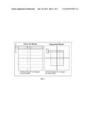
[0011] FIG. 1 depicts laser illumination scan of the detector field of view for both the narrow field of view and wide field of view modes of operation.
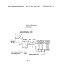
[0012] FIG. 2 is a schematic of an exemplar focal plane array with Read-out Integrated Circuit (ROIC).
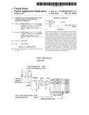
[0013] FIG. 3 is a schematic exemplar of the ROIC for a single pixel (unit cell).
[0014] The invention and its various embodiments can now be better understood by turning to the following detailed description of the preferred embodiments which are presented as illustrated examples of the invention defined in the claims.
[0015] It is expressly understood that the invention as defined by the claims may be broader than the illustrated embodiments described below.
DETAILED DESCRIPTION OF THE INVENTION
[0016] Turning now to FIGS. 1-3 wherein like references define like elements among the several views, Applicant discloses a LIDAR device and method suitable for imaging in a clear and degraded target environment.
[0017] The LIDAR system of the invention is configured to operate with two fields of regard: 1) a clear view mode (i.e., wide field of regard) and, 2) a degraded view mode (i.e., narrow field of regard).
[0018] The narrow field permits concentrating the system laser pulse on fewer pixels in order to increase penetration of degraded visual conditions and/or extend range in good visual conditions.
[0019] The wide field desirably permits a comparable or matching scene overlay with an optionally-provided system LWIR or SWIR camera.
[0020] FIG. 1 depicts how the illumination scan is projected onto the focal plane in the two different modes.
[0021] Only the illumination beam of the system is mechanically scanned; the receiver's 256×256 detectors stare into their field of view and are electrically read out as appropriate. It is expressly noted the LIDAR system of the invention is not limited to a 256×256 detector array and that any detector pixel size suitable for the user may be incorporated in the invention.
[0022] In the wide field of regard or clear air mode of FIG. 1, the illumination beam is preferably formed into a 30×3.75 degree rectangle that covers about 1/8th of the focal plane. A single pulse is fired at position 1 in the illustration of FIG. 1.
[0023] The illuminated portion of the focal plane is read out prior to the illumination beam being directed to position 2 of the clear air mode of FIG. 1.
[0024] In the degraded mode of operation of FIG. 1, the illumination beam is reduced by a factor of two in each dimension. In the degraded mode example of FIG. 1, the 15×1.875 degree beam thus covers only 1/16th of the focal plane. The illuminated pixels are read out prior to the reflected illumination beam being stepped into position 2 of the degraded mode of FIG. 1 and so on.
[0025] A small galvo, which can be precisely programmed for each mode, is desirably used to control the illumination scan. In the illustrated embodiment, the degraded mode of operation delivers about four times the laser power to each pixel, extending the range by a factor of two over the wide field of view mode or for increasing the penetration of the laser in degraded conditions to meet variable atmospheric conditions.
[0026] A preferred embodiment of the optics of the system may comprise a receiver with a six cm aperture and 72 mm focal length, optimized with 1.5 micron anti-reflection coatings and 150 um pixel size, and deviates only slightly from readily available COTS full-frame interchangeable camera lenses.
[0027] The invention comprises a receiver focal plane or FPA which may be comprised a two dimensional array of 256×256 active pixels in a preferred embodiment. Each pixel may be 150×150 microns. The use of a 150×150 micron unit cell and the 130 nm IBM BiCMOS GeSi fabrication process assure adequate bandwidth and real estate for a compact design implementation.
[0028] An exemplar structure of the focal plane array of the device is shown in FIG. 2. The four components of the focal plane may comprise two-side buttable imager/ROIC stacks. This permits the ROIC and detector arrays to be manufactured within reticle limits without stitching. Each array may comprise 128×128 pixels in a physical format of 20×20 mm. The detector array may be bump-bonded onto the ROIC. The resulting detector array may comprise dimensions of about 19.2×19.2 mm.
[0029] An exemplar ROIC unit cell circuit is shown in FIG. 3. The detector array is preferably designed with a common cathode. The bump-bonded anodes are connected to a source follower buffer.
[0030] The reflected laser pulse energy received from the target surface is integrated onto the detector's parasitic capacitor. The capacitor is initially charged by a reset switch and then released at Tzero. The reflected energy discharges the parasitic capacitor. A high pass filter differentiates the integrated signal and transforms it back into a pulse.
[0031] The amplifier of the system boosts the signal above the comparator's offset voltage. The comparator trips states whenever the reflected pulse signal transitions its threshold voltage.
[0032] The comparator's transition latches the timing circuit's state. The timing circuit comprises a ring oscillator that is held in reset until the Tzero pulse, and a counter circuit.
[0033] When the Tzero is released, the ring oscillator (inverters with an odd number of stages) begins to toggle "ones" and "zeros" at speeds that can be tailored by design. The ring oscillator's stages necessarily have propagation delay which is used to refine the reflection time of arrival measurement (the entire delay through the ring may be about two nsec).
[0034] A counter is placed at the end of the ring oscillator that accumulates the number of "ones" that pass through. When the comparator trips, both the state of the counter and the ring oscillator are captured in a series of latches.
[0035] The ring oscillator and counter continue until the end of the range gate. If a second pulse arrives within the range gate, the states are saved in a second set of latches; up to four latches per unit cell may be used if desired. This last latch can be overwritten by a subsequent return pulse, thus assuring that the last reflected pulse-per-pixel is captured. The counter may be synchronized with a master 500 MHz clock to eliminate time drifts.
[0036] Each counter latch will be 16 bits long in the illustrated embodiment. Each ring oscillator latch may be four or six bits long. Thus, with a 500 MHz master clock, the counter will allow for about a 35 cm range resolution and the ring oscillator will refine this measurement by a factor of about four or about 6.0-7.5 cm or less.
[0037] The total range gate is defined by the 16 bit counter and 500 MHz clock (2.3 Km). The length of the range gate always remains the same, but it can be positioned anywhere in space, for example to search for high reflectivity targets beyond two kilometers by holding the ROIC in reset for a specific period after the Tzero.
User Contributions:
Comment about this patent or add new information about this topic:
Images included with this patent application:
 |  |
 |  |
| Similar patent applications: | |
| Date | Title |
|---|---|
| 2011-07-21 | Liquid densitometer |
| New patent applications in this class: | |
| Date | Title |
|---|---|
| 2022-05-05 | Optical scanning device that includes waveguides |
| 2022-05-05 | Mirror assembly having reinforcement structure for light steering |
| 2022-05-05 | Three dimensional measurement device having a camera with a fisheye lens |
| 2022-05-05 | Light receiving device and range-finding device |
| 2019-05-16 | Automatic gain control for laser detector |
| New patent applications from these inventors: | |
| Date | Title |
|---|---|
| 2016-05-05 | Three dimensional recognition from unscripted sources technology (trust) |
| 2016-05-05 | Ultra-low power, ultra high thruput (ultra2) asic-based cognitive processor |
| 2015-09-24 | Ultra-high resolution digital holographic camera |
| 2015-07-02 | Hyper-spectral and hyper-spatial search, track and recognition sensor |
| Top Inventors for class "Optics: measuring and testing" | |
| Rank | Inventor's name |
|---|---|
| 1 | Robert E. Bridges |
| 2 | Yuta Urano |
| 3 | Glen A. Sanders |
| 4 | Zhiyong Li |
| 5 | Akira Hamamatsu |