Patent application title: CHANNEL FORMATION FOR THE FIXING ELEMENT OF A DENTAL SUPERSTRUCTURE AND METHOD OF MAKING THE SAME
Inventors:
Edvin Elsner (Szigetszentmiklos, HU)
IPC8 Class: AA61C800FI
USPC Class:
433174
Class name: Holding or positioning denture in mouth by fastening to jawbone by screw
Publication date: 2014-11-27
Patent application number: 20140349250
Abstract:
Channel formation for the fixing element of a dental superstructure. The
superstructure (1) is fixed to the implantation (3) integrated in the jaw
bone by means of a fixing element (2). A channel (7) is formed in the
superstructure (1). The axis line (8) of the channel (7) is shaped to
follow an arc (9) whose radii pointing to given points of the axis line
(8) diverge from the plane of the arc (9) by 0-5%. The channel (7) is
shaped in such a manner that the sections determined by the planes
perpendicular to its axis line (8) are circles with the same diameter
with their centres on the axis line (8). In the method according to the
invention a computer controlled device is used for forming the channel.Claims:
1. Channel formation for the fixing element of a dental superstructure by
using a computer controlled device said superstructure is
fixed--preferably through an interface--to the implantation integrated in
the jaw bone by means of a fixing element through an outlet hole provided
with a shoulder formed in said superstructure; to ensure insertion of
said fixing element a channel is formed in said superstructure between an
inlet hole formed in said superstructure at its side facing the oral
cavity and said shoulder of said outlet hole; said outlet hole having a
diameter corresponding to a threaded part of said fixing element is
provided in another working process, characterized in that the axis line
of said channel is shaped to follow an arc whose radii pointing to given
points of said axis line diverge from the plane of said arc by
0-.+-.5%--that is, in an advantageous case said axis line represents a
three dimensional spiral, i.e. a right-handed or left-handed helical line
instead of a two-dimensional arc; further, said channel is shaped in such
a manner that the sections determined by the planes perpendicular to its
axis line are circles with the same diameter whose centers are on said
axis line.
2. Formation of a dental superstructure according to claim 1 characterized in that said fixing element is a screw having a shank portion between its head and said threaded part, wherein the diameter of said shank portion is smaller than the diameter of said threaded part.
3. Formation of a dental superstructure according to claim 2 characterized in that in said interface threads corresponding to said threaded part of said fixing element are provided.
4. Formation of a dental superstructure according to any of claim 1 characterized in that said channel is formed by means of a spherical cutter wherein the shank diameter of the shank is at most 60% of the cutter-head diameter.
5. Method of forming a channel to accommodate the fixing element of a dental superstructure by using a computer controlled device, during the method the superstructure is fixed to the implantation integrated in the jaw bone by means of a fixing element introduced through an inlet hole of the channel and via an outlet opening formed in the superstructure, the outlet opening is provided with a shoulder, preferably, the outlet hole is bored into the superstructure from the side facing the implantation in another working process--before or after forming the channel--in such a manner that it has a diameter corresponding to the diameter of the shank of the fixing element, characterized in that between the side of the superstructure facing the oral cavity and the shoulder of the outlet opening a channel having a circular cross-section is formed by means of a spherical cutter thereby providing in the superstructure a bore-hole having a cross-section corresponding to the cross-section of the channel, the axis line of the bore-hole forms an arc in such a manner that radii running from the center of the arc and pointing to given points of the axis line of the bore-hole diverge from the plane of the arc by 0-.+-.5%, that is, in a certain case the axis line as well as the channel is formed helical, further, the channel is shaped in such a manner that the sections determined by the planes perpendicular to its axis line are circles of the same diameter with their centers on the axis line.
6. Method according to claim 5 characterized in that the channel is formed by means of a spherical cutter whose shank diameter is at most 60% of the cutter head diameter.
7. Method according to claim 5 characterized in that the superstructure is fixed to the implantation by means of a fixing element which between its head and the threaded part has a shank portion having a smaller diameter than the diameter of the threaded part.
8. Method according to any of claim 5 characterized in that the superstructure is fixed to the implantation through an intermediate piece in which threads corresponding to the threaded part of the fixing element are formed.
9. Formation of a dental superstructure according to any of claim 2 characterized in that said channel is formed by means of a spherical cutter wherein the shank diameter of the shank is at most 60% of the cutter-head diameter.
10. Formation of a dental superstructure according to any of claim 3 characterized in that said channel is formed by means of a spherical cutter wherein the shank diameter of the shank is at most 60% of the cutter-head diameter.
11. Method according to claim 6 characterized in that the superstructure is fixed to the implantation by means of a fixing element which between its head and the threaded part has a shank portion having a smaller diameter than the diameter of the threaded part.
12. Method according to any of claim 6 characterized in that the superstructure is fixed to the implantation through an intermediate piece in which threads corresponding to the threaded part of the fixing element are formed.
13. Method according to any of claim 7 characterized in that the superstructure is fixed to the implantation through an intermediate piece in which threads corresponding to the threaded part of the fixing element are formed.
Description:
[0001] The invention relates to channel formation for the fixing element
of a dental superstructure by using a computer controlled device.
[0002] The superstructure is fixed--preferably through an intermediate piece (interface)--to the implantation integrated in the jaw bone by means of a fixing element through an outlet hole provided with a shoulder. To ensure the insertion of the fixing element a channel is formed in the superstructure between an inlet hole formed in the superstructure at its side facing the oral cavity and the shoulder of the outlet hole. The outlet hole having a diameter corresponding to a threaded part of the fixing element is provided in another working process. The invention also relates to a method of forming a channel for the fixing element of a dental superstructure by using a computer controlled device.
[0003] In dentistry there is a need for replacing the missing teeth by nice and aesthetic prosthesis. To this dental implantation which is an artificial dental root made of tissue friendly material has been developed. This is implanted into the jaw bone in order to keep the artificial tooth or teeth firmly in position. In most cases the material of the implantation is pure, unalloyed Titanium. The artificial tooth or set of teeth is screwed to the implantation through a screw channel. Earlier the screw inserting direction and the screwing direction were the same, consequently the bore-hole passed through the outer, visible surface of the tooth. In this case aesthetic covering of the screw channel was rather difficult. Therefore a dental system is required in which the opening of the screw inserting channel is formed on a non-visible surface.
[0004] Patent application EP 2 289 461 A1 titled `Dental System` describes a dental superstructure comprising a screw channel with a first mouth through which screw channel a screw member is to be inserted and a screw member seat with a second mouth for providing support to the head of the screw member during fixation of the dental superstructure to a spacer element or an implant through the second mouth. At least one part of the central axis of the screw channel and a central axis of the second mouth do not coincide.
[0005] In this solution forming of the channel is rather complicated. On the one hand insertion of the screw is complicated because the varying diameter of the channel, on the other hand the dental superstructure is unreasonably weakened.
[0006] Patent application U.S. Pat. No. 5,116,225 describes an angulated abutment system for affixing a dental prosthesis to an anchor implanted in the jaw bone. The dental prosthesis can be mounted axially offset from the axis of the implant. Two components of the abutment system allow the dental prosthesis to be adjusted in small angles of rotation.
[0007] This solution also takes measures to fix the superstructure at the side facing the oral cavity, but it uses number of components production of which is complicated. Although the channel is formed straight, providing the opening from the direction of the implantation is complicated because of the number of intermediate component parts.
[0008] Patent application WO 2008/138852 describes an adapter for a dental implant with a conical connection recess in its upper part. The adapter comprises a threaded part for connection with the dental implantation and a conical main body corresponding to a conical connection recess of the implantation, a tool grip portion allowing for attachment of the adapter to the implantation by the aid of a tool, and a connection recess adapted for connection to a spacer element or a dental structure.
[0009] In this solution the spacer is provided with outer and inner threads which on the one hand is fixed in the implantation, on the other hand the superstructure is fixed in it.
[0010] Typically, this type of spacer is not used in our days since in recent times the superstructure is screwed directly into the implantation. For the sake of proper positioning of the superstructure a suitable interface may be installed between the implantation and the superstructure.
[0011] The aim of the present invention is to provide a simpler channel formation as compared to the earlier solutions, which can be implemented easily with today's technical background, which is efficient and can be automatized. It helps the dentist work faster thereby causing less inconvenience to the patient.
[0012] It has been realized that by forming the screw channel along an arched channel axis line in one process, the screw used for fixing the superstructure can be inserted easily into the space (channel) formed in the superstructure. Installation may be made easier by forming the axis line of the channel slightly spiral. This can be done in one working process by using a milling machine controlled by a computer. If a spherical cutter is used, the shoulder of the shouldered outlet hole facing the channel can be formed as a regular segment of a sphere into which the head of the fixing element can fit perfectly.
[0013] The bore-hole of the outlet hole makes it possible for the fixing element--whose lower end engaging with the shoulder is also shaped as a segment of a sphere--to take the proper position when the superstructure is fixed to the implantation. Additionally, if a screw the shank of which is made thinner above the threaded part is used as a fixing element and the interface is provided with a threaded bore-hole corresponding to the threads of the screw, then before the superstructure is placed in, after installation of the screws, the interface can be driven through the threaded part of the screws. In this manner the fixing elements are not able to fall out. In known embodiments these interfaces were only placed on the fixing element entailing the possible loss of the individual components. In case of lower denture keeping the interface in its proper place was problematic while in case of the upper denture temporary fixing of the screws was not solved.
[0014] According to the present invention formation of a channel for the fixing element of a dental superstructure by using a computer controlled device is provided. The superstructure is fixed to the implantation integrated in the jaw bone by means of a fixing element through a shouldered outlet hole formed in the superstructure. To ensure the insertion of the fixing element a channel is formed in the dental superstructure between an inlet hole formed in the superstructure at its side facing the oral cavity and the shoulder of the outlet hole. Advantageously, the outlet hole is bored into the superstructure from the side of the implantation in another working process, before or after forming the channel, in such a manner that it has a diameter corresponding to the threaded part of the fixing element. The axis line of the channel is shaped to follow an arc whose radii pointing to given points of the axis line diverge from the plane of the arc by 0-±5%--that is, advantageously the axis line represents a three dimensional spiral, i.e. a right-handed or left-handed helical line instead of a two-dimensional arc. Further, the channel is shaped in such a manner that the sections determined by the planes perpendicular to its axis line are circles of the same diameter with their centres on the axis line.
[0015] Advantageously, the fixing element is a screw having a shank portion between the screw head and the threaded part the diameter of which is smaller than the diameter of the threaded part.
[0016] Preferably, the dental superstructure is fixed to the implantation through an interface by means of a screw wherein threads corresponding to the threaded part of the screw are formed in the interface.
[0017] Advantageously, the channel is formed by means of a spherical cutter whose shank diameter is at most 60% of the cutter head diameter.
[0018] Also, according to the present invention a method of forming a channel for the fixing element of a dental superstructure by using a computer controlled device is provided. By means of a fixing element introduced through an inlet hole of the channel the superstructure is fixed via a shouldered outlet opening formed in the superstructure to the implantation integrated in the jaw bone. Advantageously, the outlet hole is bored into the superstructure from the side of the implantation in another working process, before or after forming the channel, in such a manner that it has a diameter corresponding to the diameter of the shank of the fixing element. Between the side of the superstructure facing the oral cavity and the shoulder of the outlet opening a channel having a circular cross-section is formed by means of a spherical cutter. In this process a bore-hole having a cross-section corresponding to the cross-section of the channel is formed in the superstructure wherein the axis line of the bore-hole forms an arc in such a manner that radii running from the centre of the arc and pointing to given points of the axis line of the bore-hole diverge from the plane of the arc by 0-±5%. It means that in a certain case the axis line as well as the channel is formed helical.
[0019] Further, the channel is shaped in such a manner that the sections determined by the planes perpendicular to its axis line are circles of the same diameter with their centres on the axis line.
[0020] Advantageously, the channel is formed by means of a spherical cutter whose shank diameter is at most 60% of the cutter head diameter
[0021] Preferably, the superstructure is fixed to the implantation by means of a fixing element which between the head and the threaded part has a shank portion having smaller diameter than the diameter of the threaded part.
[0022] Advantageously, the superstructure is fixed to the implantation through an interface in which threads corresponding to the threaded part of the screw are formed.
[0023] A detailed description of the invention will be given with reference to the accompanying drawings in which:
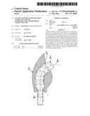
[0024] FIG. 1 is a side view showing the cross-section of an element of the superstructure;
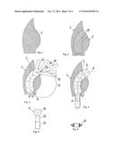
[0025] FIG. 2 is a cross-sectional side view showing the a metal sintered superstructure in which the spatial mesh framework of the channel and the outlet opening fabricated during the method can be seen;
[0026] FIG. 3 is a cross-sectional side view of the superstructure showing number of positions of the spherical cutter during channel formation;
[0027] FIG. 4 is a cross-sectional side view of the superstructure showing the process of inserting the fixing element;
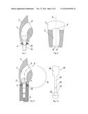
[0028] FIG. 5 is a side view of a possible embodiment of the fixing element;
[0029] FIG. 6 shows the cross-section of a possible embodiment of the interface;
[0030] FIG. 7 is a cross-sectional side view of the superstructure and the interface showing the assembled superstructure before it is fixed to the implantation;
[0031] FIG. 8 is a rear view of the cross-section of an element of the superstructure in case of helical channel formation;
[0032] FIG. 9 is a partial cross-sectional side view of the superstructure mounted on the implantation with insertion of an interface, where the fixing element is viewed from the side;
[0033] FIG. 10 shows the side view of a possible embodiment of a spherical cutter.
[0034] With the present invention a channel 7 formation is provided for aesthetical fixing of a dental superstructure (false tooth/prosthesis)--an element of which is shown in FIG. 1--to an implantation. An inlet opening 6 is formed on a side of superstructure 1 facing the oral cavity. (In case of a superstructure 1 comprising number of false teeth it is not necessary to form channel 7 in each of the teeth.) In this manner when superstructure 1 and implantation 3 are fixed together by means of fixing element 2 the filling material used for covering channel 7 will not be seen after the superstructure 1 is mounted on. In addition, the occlusal surface of the false tooth will not be formed from the filling material. Typically, forming this type of channel 7 can be important mainly in case of front teeth (FIG. 9).
[0035] Advantageously, in the simplest and most efficient way channel 7 is formed in superstructure 1 by a computer controlled device. Fixing element 2 is inserted in channel 7 formed in superstructure 1. Channel 7 is provided with an inlet opening 6 facing the oral cavity. It has a diameter large enough to receive fixing element 2 which in this example is an Allen screw (FIG. 5). The fixing element 2 comprises head 10, threaded part 11 and shank portion 12. In superstructure 1 the channel 7 extends to the shoulder 4 of outlet opening 5. Shoulder 5 provides a seat for the head 10 of the fixing element 2. Threaded part 11 and major part of the shank portion 12 of the fixing element 2 are driven out through outlet opening 5 of channel 7 before superstructure 1 is mounted on. Head 10 of fixing element 2 is seated on the inner side of shoulder 4 which is shaped as a segment of a sphere. The surface of head 10 of the fixing element 2 facing shoulder 4 is also shaped as a segment of a sphere. The outlet hole 5 is bored into the superstructure 1 from the side of the implantation 3 in another working process, before or after forming the channel 7, in such a manner that it has a diameter corresponding to the diameter of the threaded part 11 of the fixing element 2.
[0036] According to the present invention the axis line 8 of channel 7 forms an arc 9. Arc 9 representing axis line 8 of channel 7 may also be formed in such a manner that it diverges from its own plane by a few degrees, at most by 0-±5°. In this manner a slightly diverging spiral path is produced along the periphery of arc 9 (FIG. 8). That is, advantageously the axis line 8 represents a three dimensional spiral, i.e. a right-handed or left-handed helical line instead of a two-dimensional arc 9. The cross-section of channel 7 is essentially constant. It narrows only at outlet opening 5 to have a diameter corresponding to the diameter of outlet opening 5 (FIG. 7).
[0037] Fixing element 2 is a screw having a shank portion 12 between head 10 and threaded part 11 the diameter of which is smaller than the diameter of the threaded part 11.
[0038] In many cases an interface 13 (FIG. 6) is placed between superstructure 1 and implantation 3 which are fixed together by means of fixing element 2. In order to make mounting of superstructure 1 on implantation 3 easier, threads corresponding to the threaded part 11 of the fixing element 2 are formed in the interface 13. Thus after introduction of fixing element 2 in superstructure 1 interface 13 can be driven through threaded part 11 of fixing element 2 onto shank portion 12. In this manner both interface 13 and fixing element 2 are prevented from falling out when superstructure 1 is mounted on implantation 3. At the same time insertion of fixing element 2 into implantation 3 is not inhibited by interface 13.
[0039] To form channel 7 a spherical cutter 14 is used. The cutter head is not necessarily ball-shaped it can be dome-shaped or it may have the shape of a segment of sphere. The cutter head 17 of spherical cutter 14 used in the present invention is ball-shaped. In the present example the shank diameter 16 of shank 15 of spherical cutter 14 is 30% of the diameter of the cutter head 18 (FIG. 3). Shank end 20 of shank 15 can be inserted in the computer controlled device (FIGS. 3 and 10). The path in which the cutter head 17 proceeds is also shown in FIG. 3 while FIG. 4 shows the travel of fixing element 2 in channel 7 during insertion.
[0040] Implantation can be produced with great accuracy in a highly productive metal sintering method. Much material and work can be saved during manufacture if a spatial mesh framework 19 is formed in the space of channel 7. Spatial mesh framework 19 ensures that satisfactorily dense material can be built on the other parts of implantation 3. Considering that the material used for making the implantation is very expensive, this solution may result in significant material savings. Between the frame elements of the spatial mesh framework 19 the space angle is 30°. This framework ensures the required static structure and accuracy. Removal of these supporting elements can be done on completion of the metal sintering method as described previously.
[0041] According to the invention the method of forming channel 7 for receiving fixing element 2 of dental superstructure 1 is accomplished by means of a computer controlled device. During the method a channel 7 with a circular cross-section is formed from the side of the superstructure 1 facing the oral cavity to the shoulder 4 of outlet opening 5 by means of a spherical cutter 14 (FIG. 3). To this a bore-hole having a cross-section corresponding to the cross-section of the channel 7 is formed in the superstructure 1 wherein the axis line 8 of the bore-hole forms an arc 9 in such a manner that radii running from the centre of the arc 9 and pointing to given points of the axis line 8 of the bore-hole diverge from the plane of the arc 9 by 0-±5%. It means that in a certain case the axis line 8 as well as channel 7 is formed helical (FIG. 8). The axis of the threaded bore-hole formed in the implantation 3 is tangential to axis line 8. Further, the channel 7 is shaped in such a manner that the sections determined by the planes perpendicular to its axis line 8 are circles of the same diameter with their centres on the axis line 8.
[0042] To form the channel 7 a spherical cutter 14 is used. The diameter of the cylindrical shank 15 of the spherical cutter 14 is at most 60% of the diameter of the cutter head 18. In this example it is 30%.
[0043] Implantation 3 can be made of any biologically compatible metal and ceramic material. Usually, the material of superstructure 1 is zirconium (Zr), cobalt-chrome alloy, titanium, etc. Naturally, any kind of material used in dental technology may be suitable.
[0044] Outlet opening 5 can be formed on the surface of superstructure 1 facing implantation 3 by a simple boring process. To cut channel 7 a high precision five-axle milling machine is used with a spherical cutter 14 which is driven along a two or three dimensional (spiral) path. Shaping is carried out by means of cutter-head 17 having a shank 15 with a shank diameter 16 smaller than the cutter-head diameter 18. This makes it possible that concave, so called undercut surfaces can be shaped from the direction of work.
[0045] Then fixing element 2 can be introduced easily in channel 7.
[0046] According to the embodiment of present invention the screwing direction and the screw insertion direction are on the same arc. The two or three dimensional (spiral) path tangential to the axis of the implantation at the same time corresponds to the screw insertion direction. Consequently, unnecessary procedure which would weaken the implantation can be avoided. Since all the channel elements are parallel with each other, a statically stronger structure can be obtained as compared to the earlier channel formations some portions of which were significantly widened. The embodiment according to the present invention provides a high level solution both in terms of aesthetics and assembly technique. It is aesthetic, since the screw insertion direction cannot be seen when the person wearing the prosthesis is talking. In respect of assembly technique the solution according to the present invention makes it possible for the dentist to screw the implantation to its place by means of a device tilted towards the oral cavity. In this case the opposing row of teeth is not in the way of the operation.
User Contributions:
Comment about this patent or add new information about this topic:
Images included with this patent application:
 |  |
 |
| Similar patent applications: | |
| Date | Title |
|---|---|
| 2015-02-26 | Photon induced acoustic streaming device and method |
| 2015-02-12 | Apparatus for dental treatment |
| 2015-02-12 | Apparatus and methods for cleaning teeth |
| 2015-02-19 | Methods for extracting a tooth |
| 2015-02-26 | Tool for bonding orthodontic bracket |
| New patent applications in this class: | |
| Date | Title |
|---|---|
| 2022-05-05 | Zygomatic implant with partially interrupted threaded portion |
| 2019-05-16 | Disposition introduced in dental implant pin |
| 2016-09-01 | One piece custom made dental device for holding multiple teeth |
| 2016-06-16 | Dental implant with coronal groove structure |
| 2016-06-16 | Implants for enhanced anchoring within bone |
| New patent applications from these inventors: | |
| Date | Title |
|---|---|
| 2015-11-05 | Dental device fixing unit secured resiliently into implants and/or dental device fixing unit secured into implants enabling optional angular position adjustment |
| Top Inventors for class "Dentistry" | |
| Rank | Inventor's name |
|---|---|
| 1 | Zachary B. Suttin |
| 2 | Eric Kuo |
| 3 | Bruce Berckmans, Iii |
| 4 | Marc Peuker |
| 5 | Sumita B. Mitra |