Patent application title: Slip resistant knee and elbow pad
Inventors:
Hung-Yu Hsieh (Changhua, TW)
IPC8 Class: AA41D13015FI
USPC Class:
2 16
Class name: Apparel guard or protector hand or arm
Publication date: 2014-11-06
Patent application number: 20140325729
Abstract:
A joint protector for protecting a human user's knee or elbow from injury
is provided with an internally hollowed body formed of a shock absorbing
foam material; two opposite sleeves formed of fabric and sewn to a
periphery of the body; two flexible inner tubes disposed in the sleeves
respectively; and a plurality of plastic cords disposed in each inner
tube. The joint protector can increase resistance to slip when it is worn
on the knee or the elbow.Claims:
1. A joint protector for protecting a human user's knee or elbow from
injury, comprising: an internally hollowed body formed of a shock
absorbing foam material; two sleeves formed of fabric and secured to a
periphery of the internally hollowed body; two flexible inner tubes
disposed in the sleeves respectively; and a plurality of plastic cords
disposed in each of the flexible inner tubes.Description:
BACKGROUND OF THE INVENTION
[0001] 1. Field of the Invention
[0002] The invention relates to pads for protecting knees and/or elbows and more particularly to a slip resistant knee and elbow pad.
[0003] 2. Description of Related Art
[0004] Elbow pads are protective padded gear worn on the elbows to protect them against injury during a fall or a strike. Elbow pads are worn by many athletes, such as cyclists, roller skaters, skateboarders, volleyball players, skiers and wrestlers.
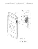
[0005] It is understood that the pad may become loosened after a period time of use due to elastic fatigue of the pad. For overcoming the problem, a conventional elbow pad A is shown in FIG. 1. The cylindrical A comprises two opposite, longitudinal elastic metal members B each including a plurality of rings B1 formed integrally. However, a user may feel uncomfortable on the elbow due to force exerted on the elbow by the densely arranged rings B1. Further, the metal members B may get rusted after a period time of use. And in turn, it may compromise the tightening effect of the metal members B.
[0006] Thus, the need for improvement still exists.
SUMMARY OF THE INVENTION
[0007] It is therefore one object of the invention to provide a joint protector for protecting a human user's knee or elbow from injury, comprising an internally hollowed body formed of a shock absorbing foam material; two opposite sleeves formed of fabric sewn to a periphery of the body; two flexible inner tubes disposed in the sleeves respectively; and a plurality of plastic cords disposed in each of the inner tubes
[0008] The above and other objects, features and advantages of the invention will become apparent from the following detailed description taken with the accompanying drawings.
BRIEF DESCRIPTION OF THE DRAWINGS
[0009] FIG. 1 is a perspective view of a conventional elbow pad;
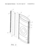
[0010] FIG. 2 is an exploded view of a joint protector according to a first preferred embodiment of the invention;
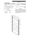
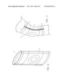
[0011] FIG. 3 is a perspective view of the assembled joint protector;
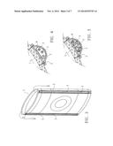
[0012] FIG. 4 is an enlarged portion of a sectional view of the joint protector of FIG. 3;
[0013] FIG. 5 is a view similar to FIG. 4 showing another configuration having more plastic cords;
[0014] FIG. 6 is a perspective view of a joint protector according to a second preferred embodiment of the invention;
[0015] FIG. 7 is an environmental view of the joint protector worn on the knee of an individual;
[0016] FIG. 8 is an exploded view of a joint protector according to a third preferred embodiment of the invention;
[0017] FIG. 9 is a perspective view of the assembled joint protector of FIG. 8;
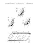
[0018] FIG. 10 is an enlarged portion of a sectional view of the joint protector of FIG. 9;
[0019] FIG. 11 is a view similar to FIG. 10 showing another configuration having more plastic cords;
[0020] FIG. 12 is a view similar to FIG. 10 showing still another configuration having less plastic cords; and
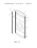
[0021] FIG. 13 is an exploded view of a joint protector according to a fourth preferred embodiment of the invention.
DETAILED DESCRIPTION OF THE INVENTION
[0022] Referring to FIGS. 2 to 5, joint protector in accordance with a first preferred embodiment of the invention comprises the following components as discussed in detail below.
[0023] An internally hollowed body 1 has an oval section and is formed of a shock absorbing foam material. Two opposite sleeves 2 made of fabric are sewn to an outer surface of the body 1. Two inner tubes 4 made of flexible material are disposed in the sleeves 2 respectively. A plurality of plastic cords 3 are disposed in each of the inner tubes 4. The number of the plastic cords 3 can be decreased (see FIG. 4) or increased (see FIG. 5) subject to design choice.
[0024] Referring to FIGS. 6 and 7, joint protector in accordance with a second preferred embodiment of the invention is shown. The characteristics of the second preferred embodiment are substantially the same as that of the first preferred embodiment except the following:
[0025] The sleeves 2 are sewn to an inner surface of the body 1. The inner tubes are eliminated. The plastic cords 3 are disposed in each of the sleeves 2.
[0026] Referring to FIGS. 8 to 12, joint protector in accordance with a third preferred embodiment of the invention is shown. The characteristics of the third preferred embodiment are substantially the same as that of the first preferred embodiment except the following:
[0027] The inner tubes are eliminated. The plastic cords 3 are disposed in each of the sleeves 2.
[0028] It is noted that in addition to the three plastic cords configuration (see FIG. 10), the number of the plastic cords 3 can be increased (see FIG. 11) or decreased (see FIG. 12) subject to design choice.
[0029] Referring to FIG. 13, joint protector in accordance with a fourth preferred embodiment of the invention is shown. The characteristics of the fourth preferred embodiment are substantially the same as that of the first preferred embodiment except the following:
[0030] The inner tubes are eliminated. The plastic cords 3 are disposed in each of the convex sleeves 2. Opposite hook and loop type fastener cords 1A and 2A are formed on an inner surface of each of the sleeves 2 and an outer surface of the body 1 respectively. It is understood that the sleeve 2 can be quickly bounded on or released from the body 1 by engaging the hook and loop type fastener cords 2A, 1A together or disengaging them from each other.
[0031] It is envisaged by the invention that the joint protector can increase resistance to slip when it is worn on the elbow or the knee of an individual.
[0032] While the invention has been described in terms of preferred embodiments, those skilled in the art will recognize that the invention can be practiced with modifications within the spirit and scope of the appended claims.
User Contributions:
Comment about this patent or add new information about this topic:
| People who visited this patent also read: | |
| Patent application number | Title |
|---|---|
| 20150041621 | COMBINATION DOMESTIC APPLIANCE MOUNTING SYSTEM WITH SERVICE CAPABILITY |
| 20150041620 | INTEGRATED TYPE ENGINE MOUNT FOR VEHICLE |
| 20150041619 | NON-ROTATING FLEXURE BEARINGS FOR CRYOCOOLERS AND OTHER DEVICES |
| 20150041618 | QUAY CRANE |
| 20150041617 | MOUNTING MEMBER FOR VIBRATION DAMPING DEVICE AND VIBRATION DAMPING DEVICE USING THE SAME |
Images included with this patent application:
 |  |
 |  |
 |  |
 |  |
| Similar patent applications: | |
| Date | Title |
|---|---|
| 2015-01-22 | Bullet resistant abdominal binder |
| 2015-02-26 | Ventilated, cut-resistant hockey sock |
| 2015-03-19 | Garment adapted to be associated to a device for the personal protection of a user |
| 2014-09-11 | Slip-resistant hosiery |
| 2015-03-19 | Head circumference adjustment device of a helmet |
| New patent applications in this class: | |
| Date | Title |
|---|---|
| 2017-08-17 | Multi-layer medical glove |
| 2017-08-17 | Pantleg holding mechanism for knee pads |
| 2016-12-29 | Sports glove |
| 2016-09-01 | Anatomically adaptive joint protector |
| 2016-06-30 | Water sports hand cover |
| Top Inventors for class "Apparel" | |
| Rank | Inventor's name |
|---|---|
| 1 | William L. Grilliot |
| 2 | Mary I. Grilliot |
| 3 | David Turner |
| 4 | Patricia K. Waters |
| 5 | Caleb Clark Crye |