Patent application title: Turbine Nozzle for Air Cycle Machine
Inventors:
Craig M. Beers (Wethersfield, CT, US)
Craig M. Beers (Wethersfield, CT, US)
Brent J. Merritt (Southwick, MA, US)
Brent J. Merritt (Southwick, MA, US)
Assignees:
HAMILTON SUNDSTRAND CORPORATION
IPC8 Class: AF01D904FI
USPC Class:
415191
Class name: Plural distributing means immediately upstream of runner arcuately or circularly arranged around runner axis vanes
Publication date: 2014-10-30
Patent application number: 20140322000
Abstract:
A nozzle for use in an air cycle machine has a plate. A plurality of
vanes extends in a second axial direction away from the plate. The
plurality of vanes extends for a height away from the plate and a width
defined as the closest distance between two adjacent vanes, with a ratio
of the nozzle height to the nozzle width being between 0.3563 and 0.4051.
An air cycle machine and a method are also disclosed.Claims:
1. A nozzle for use in an air cycle machine comprising: a plate; a
plurality of vanes extending away from said plate, with said plurality of
vanes extending for a height away from said plate and a width being
defined as the closest distance between two adjacent vanes, with a ratio
of said height to said width being between 0.3563 and 0.4051.
2. The nozzle for use in an air cycle machine as set forth in claim 1, wherein there are 19 circumferentially spaced ones of said vanes.
3. The nozzle for use in an air cycle machine as set forth in claim 2, wherein a total flow area is defined between all 19 of said vanes and said total flow area being between 0.3963 and 0.4505 square inches (2.5565-2.9066 centimeters).
4. The nozzle as set forth in claim 3, wherein said plate is formed of a base aluminum material provided with a tungsten carbide erosion coating.
5. The nozzle for use in an air cycle machine as set forth in claim 1, wherein a total flow area is defined between all 19 of said vanes and said total flow area being between 0.3963 and 0.4505 square inches (2.5565-2.9066 centimeters).
6. The nozzle as set forth in claim 1, wherein said plate is formed of a base aluminum material provided with a tungsten carbide erosion coating.
7. An air cycle machine comprising: a turbine rotor configured to drive a shaft, and a compressor rotor driven by said shaft, and a fan rotor driven by said shaft; and a nozzle provided adjacent said turbine rotor with said nozzle being at a location upstream of said turbine rotor; said nozzle including a plate, a plurality of vanes extending in a second axial direction away from said plate, with said plurality of vanes extending for a height away from said plate and a width being defined as the closest distance between two adjacent vanes, with a ratio of said height to said width being between 0.3563 and 0.4051.
8. The air cycle machine as set forth in claim 7, wherein there are 19 circumferentially spaced ones of said vanes.
9. The air cycle machine as set forth in claim 8, wherein a total flow area is defined between all 19 of said vanes and said total flow area being between 0.3963 and 0.4505 square inches (2.5565-2.9066 centimeters).
10. The air cycle machine as set forth in claim 9, wherein said plate is formed of a base aluminum material provided with a tungsten carbide erosion coating.
11. The air cycle machine as set forth in claim 9, wherein said nozzle is a primary nozzle and is associated with a slider that moves relative to said primary nozzle dependent on flow condition to change a flow area, with said slider being movable between a closed position and a more open position, and said total flow area being defined at said closed position.
12. The air cycle machine as set forth in claim 11, wherein said slider is biased to the more open position.
13. The air cycle machine as set forth in claim 7, wherein a total flow area is defined between all 19 of said vanes and said total flow area being between 0.3963 and 0.4505 square inches (2.5565-2.9066 centimeters).
14. The air cycle machine as set forth in claim 7, wherein said plate is formed of a base aluminum material provided with a tungsten carbide erosion coating.
15. A method of repairing an air cycle machine comprising the steps of: (a) removing a nozzle from a location adjacent a turbine rotor in an air cycle machine, and replacing said removed nozzle with a replacement nozzle; and (b) the replacement nozzle including a plate, and a plurality of vanes extending away from said plate, with said plurality of vanes extending for a height away from said plate and a width being defined as the closest distance between two adjacent vanes, with a ratio of said height to said width being between 0.3563 and 0.4051.
16. The method as set forth in claim 15, wherein there are 19 circumferentially spaced ones of said vanes.
17. The method as set forth in claim 16, wherein a total flow area is defined between all 19 of said vanes and said total flow area being between 0.3963 and 0.4505 square inches (2.5565-2.9066 centimeters).
18. The method as set forth in claim 17, wherein said plate is formed of a base aluminum material provided with a tungsten carbide erosion coating.
19. The method as set forth in claim 15, wherein a total flow area is defined between all 19 of said vanes and said total flow area being between 0.3963 and 0.4505 square inches (2.5565-2.9066 centimeters).
20. The method as set forth in claim 15, wherein said plate is formed of a base aluminum material provided with a tungsten carbide erosion coating.
Description:
BACKGROUND
[0001] This application relates to a turbine nozzle for use in an air cycle machine.
[0002] Air cycle machines are known and, typically, provide air as part of a cabin air conditioning and temperature control system on an aircraft.
[0003] An air cycle machine typically includes at least one turbine receiving a source of compressed air and driving a compressor. The combination of the turbine and compressor condition the air for use on the aircraft.
SUMMARY
[0004] A nozzle for use in an air cycle machine has a plate. A plurality of vanes extends for a height away from the plate and a width is defined as the closest distance between two adjacent vanes. A ratio of the height to the width is between 0.3563 and 0.4051. An air cycle machine and a method of repair are also disclosed.
[0005] These and other features may be best understood from the following drawings and specification.
BRIEF DESCRIPTION OF THE DRAWINGS
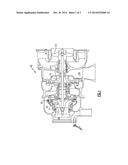
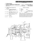
[0006] FIG. 1 shows an air cycle machine.
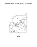
[0007] FIG. 2 shows a detail of a turbine rotor and nozzle.
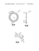
[0008] FIG. 3A shows a primary nozzle portion.
[0009] FIG. 3B is a cross-sectional view along line B-B of FIG. 3A.
[0010] FIG. 3C shows a further detail.
DETAILED DESCRIPTION
[0011] An air cycle machine 20 incorporates a turbine rotor 22 as shown in FIG. 1. A compressor rotor 32 receives a source of compressed air 126 and further compresses the air. The compressed air is delivered into an inlet and passes over turbine rotor 22 and to an outlet 26. Outlet 26 communicates into an aircraft cabin. The turbine rotor 22 drives a shaft 23 to, in turn, rotate a fan rotor 122 and a compressor rotor 32.
[0012] A primary nozzle 28 and secondary nozzle 21 condition the air from the inlet 24 as it approaches the turbine rotor 22.
[0013] As shown in FIG. 2, the turbine rotor 22 is positioned radially inwardly of a primary nozzle 28. A shroud 50 is incorporated with secondary nozzle 21, and is positioned to surround the rotor 22 and pass in a downstream direction from the primary nozzle 28. A nozzle slider 52 is biased by a spring 54 away from the nozzles 21 and 28.
[0014] During ground operation, a pressure in the turbine inlet chamber 24 is sufficiently high to overcome a force from spring 54. The slider 52, thus, sits in the closed position as illustrated.
[0015] At higher altitude, the relationship described above is no longer true and the slider 52 can move to the left as shown in this Figure and increase a nozzle flow area. More air is needed for cooling the aircraft cabin on the ground, and this nozzle combination provides more while an associated aircraft is on the ground.
[0016] The primary nozzle 28 is illustrated in FIG. 3A having a plate 38 and a plurality of vanes 40 extending in an axial direction away from the plate 38. The axial direction is defined and measured relative to a center axis C.
[0017] As shown in FIG. 3B, the vanes 40 extend away from the plate 38 by a distance d1.
[0018] As shown in FIG. 3C, adjacent vanes 40 are spaced by a width at a closest location d2. In embodiments, there were 19 of the nozzle vanes 40. The nozzle height d1 was 0.092 inch (0.234 centimeters). The nozzle width d2 was 0.24 inch (0.610 centimeters). The width is measured tangent or parallel to the sides of the airfoils on adjacent vanes 40, and the point where they are most closely spaced. A total nozzle flow area between the plurality of vanes 19 at the closed position, was 0.423 square inches (2.729 square centimeters).
[0019] In embodiments, a ratio of d1 to d2 was between 0.3563 and 0.4051. The total nozzle flow area may range between 0.3963 and 0.4505 square inches (2.5565-2.9066 centimeters).
[0020] The nozzle 28 has a tungsten carbide erosion coating. Nozzle 287 is formed of a base of aluminium and then provided with a tungsten carbide erosion coating. Preferably, a high velocity oxy fuel coating technique is provided utilizing continuous burning.
[0021] A method of repairing an air cycle machine 20 includes the steps of removing a nozzle 28 from a location adjacent a turbine rotor in an air cycle machine. A replacement nozzle 28 is then mounted adjacent the turbine.
[0022] The secondary nozzle and shroud 21 is disclosed and claimed in co-pending application Ser. No. ______, Attorney docket number PA 25465 US; 67010-489US1, entitled Turbine Nozzle and Shroud for Air Cycle Machines, and filed on even date herewith.
[0023] Although an embodiment of this invention has been disclosed, a worker of ordinary skill in this art would recognize that certain modifications would come within the scope of this disclosure. For that reason, the following claims should be studied to determine the true scope and content of this disclosure.
User Contributions:
Comment about this patent or add new information about this topic:
Images included with this patent application:
 |  |
 |  |
| Similar patent applications: | |
| Date | Title |
|---|---|
| 2014-10-30 | Turbine nozzle for air cycle machine |
| 2014-10-30 | Turbine nozzle and shroud for air cycle machine |
| 2014-10-30 | Turbine nozzle and shroud for air cycle machine |
| 2014-10-30 | Turbine nozzle piece parts with hvoc coatings |
| 2014-11-06 | Stator component with segmented inner ring for a turbomachine |
| New patent applications in this class: | |
| Date | Title |
|---|---|
| 2017-08-17 | Nozzle box assembly |
| 2016-06-02 | Axial flow expander |
| 2016-04-21 | Air turbine for applications in wave energy conversion |
| 2016-01-14 | Turbine nozzle components having reduced flow areas |
| 2016-01-07 | Gas turbine engine stator vane assembly with split shroud |
| New patent applications from these inventors: | |
| Date | Title |
|---|---|
| 2021-11-04 | Method of repair to compressor housing and repaired housing |
| 2021-02-04 | Motor and bearing cooling paths |
| 2021-02-04 | Motor and bearing cooling paths |
| Top Inventors for class "Rotary kinetic fluid motors or pumps" | |
| Rank | Inventor's name |
|---|---|
| 1 | Gabriel L. Suciu |
| 2 | Frederick M. Schwarz |
| 3 | United Technologies Corporation |
| 4 | Brian D. Merry |
| 5 | Craig M. Beers |