Patent application title: CONNECTOR ASSEMBLY
Inventors:
Zhi-Ming Zhu (Wuhan, CN)
Ming-Hui Luo (Wuhan, CN)
Ting Wang (Wuhan, CN)
San-Yong Yang (Wuhan, CN)
San-Yong Yang (Wuhan, CN)
Assignees:
HON HAI PRECISION INDUSTRY CO., LTD.
HONG FU JIN PRECISION INDUSTRY (WUHAN) CO., LTD.
IPC8 Class: AH01R13642FI
USPC Class:
439357
Class name: Retaining means finger or stretchable sleeve resiliently urged laterally of connection resilient finger
Publication date: 2014-10-16
Patent application number: 20140308841
Abstract:
A connector assembly includes a first connector and a second connector.
The first connector defines a plurality of inserting holes. A receiving
slit defined between adjacent two of the plurality of inserting holes.
The second connector includes a plurality of pins. A positioning piece is
formed between adjacent two of the plurality of pins. The second
connector is inserted in the first connector when the positioning piece
is aligned to the receiving slit. The positioning piece abuts an outer
portion of the first connector to prevent the second connector from being
wrongly inserted in the first connector when the positioning piece is not
aligned to the receiving slit.Claims:
1. A connector assembly, comprising: a first connector comprising a
plurality of inserting holes, a receiving slit defined between adjacent
two of the plurality of inserting holes; and a second connector
comprising a plurality of pins, a positioning piece formed between
adjacent two of the plurality of pins; wherein the second connector is
configured to be inserted in the first connector when the positioning
piece is aligned to the receiving slit, and the positioning piece is
configured to abut an outer portion of the first connector and prevent
the second connector from being inserted in the first connector when the
positioning piece is not aligned to the receiving slit.
2. The connector assembly of claim 1, wherein adjacent two of the plurality of inserting holes are separated by a separating piece.
3. The connector assembly of claim 2, wherein the receiving slit is defined in the separating piece.
4. The connector assembly of claim 1, wherein a height of the positioning piece is smaller than a depth of the receiving slit.
5. The connector assembly of claim 1, wherein the first connector comprises an engaging portion, the second connector comprises a clasp, and the clasp is configured to engage on the engaging portion when the second connector is inserted in the first connector.
6. The connector assembly of claim 5, wherein the receiving slit is adjacent to the engaging portion, and the positioning piece is located adjacent to the clasp.
7. The connector assembly of claim 1, wherein the plurality of inserting holes are aligned in a two by two grid.
8. The connector assembly of claim 7, wherein the plurality of pins are aligned to the two by two grid.
9. A first connector, comprising: a plurality of side walls and a top wall connected to each of the plurality of side walls; a plurality of inserting holes defined in the top wall, a separating piece separating each adjacent two of the plurality inserting holes; a receiving slit defined in the separating piece; and an engaging portion formed on one of the plurality of side walls and located adjacent to the receiving slit.
10. The first connector of claim 9, wherein the plurality of inserting holes are aligned in a two by two grid.
11. A second connector, comprising: a plurality of side pieces and a bottom piece connected to each of the plurality of side pieces; a plurality of pins formed on the bottom piece; a positioning piece connected between adjacent two of the plurality of pins; and a clasp formed on one of the plurality of side pieces and located adjacent to the positioning piece.
12. The second connector of claim 11, wherein the plurality of pins are aligned in a two by two pins.
Description:
BACKGROUND
[0001] 1. Technical Field
[0002] The present disclosure relates to connector assemblies, and particularly to a connector assembly with a foolproof mechanism.
[0003] 2. Description of Related Art
[0004] A connector assembly is used for transmitting data between two electronic devices. The connector assembly includes a first connector with a plurality of inserting slots and a second connector with a plurality of plugs. Each of the plugs must be inserted into each of the inserting slots before the connector assembly can function. However, one of the plugs maybe easily inserted in a wrong direction. Therefore, there is room for improvement in the art.
[0005] Therefore, there is room for improvement in the art.
BRIEF DESCRIPTION OF THE DRAWINGS
[0006] Many aspects of the embodiments can be better understood with reference to the following drawings. The components in the drawings are not necessarily drawn to scale, the emphasis instead being placed upon clearly illustrating the principles of the embodiments. Moreover, in the drawings, like reference numerals designate corresponding parts throughout the several views.
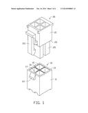
[0007] FIG. 1 is an exploded, isometric view of an embodiment of a connector assembly.
[0008] FIG. 2 is an isometric view of a second connector of the connector assembly of FIG. 1.
[0009] FIG. 3 is an assembled view of the connector assembly of FIG. 1.
[0010] FIG. 4 is an isometric view of connector assembly of FIG. 1.
DETAILED DESCRIPTION
[0011] The disclosure is illustrated by way of example and not by way of limitation in the figures of the accompanying drawings in which like references indicate similar elements. It should be noted that references to "an" or "one" embodiment in this disclosure are not necessarily to the same embodiment, and such references mean "at least one."
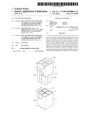
[0012] FIGS. 1 and 2 illustrates an embodiment of a connector assembly. The connector assembly includes a first connector 10 and a second connector 20.
[0013] The first connector 10 is a formed in a rectangular block and includes four side walls 11 and a top wall 13 perpendicularly connected to the four side walls 11. An engaging portion 111 is protruded on one of the four side walls 11. The top wall 13 of the first connector 10 defines four inserting holes 15 which are aligned in two lines and two rows. Two adjacent inserting holes 15 are separated by a separating piece 16. The separating piece 16 is formed in a "+" shape. A receiving slit 17 is defined in the separating piece 16 and located adjacent the engaging portion 111.
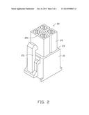
[0014] The second connector 20 includes four side walls 21 and a bottom wall 23 perpendicularly connected to the four side walls 21. One of the four side walls 21 defines a clasp 211 corresponding to the engaging portion 111 of the first connector 10. Four pins 25 are formed in the bottom wall 23. The pins 25 are downwardly extending and located in two lines and two rows. A positioning piece 251 is formed on the connector 20 adjacent the clasp 211. The positioning piece 251 is connected between two adjacent pins 25. A height of the positioning piece 251 is smaller than a depth of the receiving slit 17.
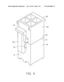
[0015] FIG. 3 shows that when the second connector 20 is connected to the first connector 10 in a right direction, the positioning piece 251 is aligned to the receiving slit 17. The pins 25 of the second connector 20 are inserted in the inserting slots 15 of the first connector 10. The positioning piece 251 is inserted in the receiving slit 17. The bottom piece 23 of the second connector 20 abuts the top wall 13 of the first connector 10. Simultaneously, the clasp 211 engages on the engaging portion 111 to secure the first connector 10 to the second connector 20.
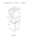
[0016] FIG. 4 shows that when the second connector 20 is connected to the first connector 10 in a wrong direction, the positioning piece 251 of the second connector 20 is misaligned with the receiving slit 17 of the first connector 10. When the second connector 20 is inserted in the first connector 10, the positioning piece 251 of the second connector 20 abuts the separating piece 16 of the first connector 10 to prevent the second connector 20 from being wrongly connected to the first connector 10.
[0017] It is to be understood, however, that even though numerous characteristics and advantages of the embodiments have been set forth in the foregoing description, together with details of the structure and functions of the embodiments, the disclosure is illustrative only, and changes may be made in detail, especially in the matters of shape, size, and arrangement of parts within the principles of the present disclosure to the full extent indicated by the broad general meaning of the terms in which the appended claims are expressed.
User Contributions:
Comment about this patent or add new information about this topic:
| People who visited this patent also read: | |
| Patent application number | Title |
|---|---|
| 20150286256 | Micro-Hole Vents for Device Ventilation Systems |
| 20150286255 | VARIABLE FRICTION CLUTCH FOR A PORTABLE COMPUTER |
| 20150286254 | Tablet Projecting System with Modular External Connection |
| 20150286253 | DISPLAY DEVICE |
| 20150286252 | Docking Station Apparatus for a Portable Device |
Images included with this patent application:
 |  |
 |  |
 |
| Similar patent applications: | |
| Date | Title |
|---|---|
| 2014-09-18 | Connector assembly with receptacle carriers |
| 2014-09-18 | Twist lock connector assembly |
| 2014-09-18 | Latching connector assembly |
| 2014-09-18 | Connector assembly for an electronic device |
| 2014-09-18 | Connector assembly and method for using |
| New patent applications in this class: | |
| Date | Title |
|---|---|
| 2018-01-25 | Connector |
| 2016-06-09 | Connector |
| 2016-04-07 | Electrical connector system |
| 2016-03-03 | Electrical connector and combination of an electronic device and the electrical connector |
| 2015-12-31 | Connector |
| New patent applications from these inventors: | |
| Date | Title |
|---|---|
| 2016-06-30 | Electronic device assembly |
| 2016-06-09 | Electronic device with bracket for disk drive |
| 2016-04-21 | Securing structure for expansion card |
| 2015-11-05 | Power supply |
| 2015-09-24 | Heat dissipation device |
| Top Inventors for class "Electrical connectors" | |
| Rank | Inventor's name |
|---|---|
| 1 | Jerry Wu |
| 2 | Noah Montena |
| 3 | Qi-Sheng Zheng |
| 4 | Jun Chen |
| 5 | Norman R. Byrne |