Patent application title: Grripz comfort handle for carrying bags and other items
Inventors:
Jason Liszkiewicz (Brooklyn, NY, US)
IPC8 Class: AA45F510FI
USPC Class:
294171
Class name: Handling: hand and hoist-line implements article carrier gripped and carried by hand having cord or bail accommodating groove or passage along length of handle
Publication date: 2014-10-02
Patent application number: 20140292011
Abstract:
It is common to see people carrying shopping bags as well as objects with
hard handles. Both soft handles and hard handles can create discomfort
during transport. The invention presented here is for a moderately
flexible yet firm handle-grip/hand grip apparatus (named "Grripz") that
enables people to comfortably carry a variety of loaded bag types or
weighted objects that need to be carried by hand that allows for the
attachment of some type of handle or hand grip. The material and design
relieves discomfort while providing adequate support during transport.Claims:
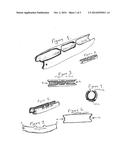
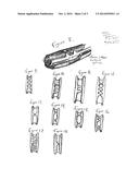
1. The protrusion(s) located at the outer face as seen in FIGS. 1, 2, 3,
5, 8, 9, 10, 11, 12, 13, 14, 15, 16, 17, 18, and 19 of the portable,
removable, reusable handlegrip/hand-grip apparatus which is intended for
the use of carrying various bags or other contraptions that require the
use of a person's hand. These protrusion(s) are flexible and allow the
pushing in and pulling out of various handles or other materials that
could be used in the aid of carrying weighted objects such as plastic bag
handles, fabric handles, twine, metal paint can handles, leather handles,
hard plastic handles, paper handles, rope, string, or wire. The
protrusion(s)are also firm enough to provide the ability of the
handle-grip/hand-grip apparatus to remain attached to a bag handle when a
person removes his or her hand from the handle-grip/hand-grip apparatus.
The design of the protrusion(s) can vary, emerging from two opposing
sides of the outer top face of the handle-grip/hand grip apparatus as
seen in FIGS. 1, 2, 3, 5, 8, 9, 12, 13, 14, 15, 16, and 17, or emerging
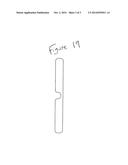
from one side of the outer top face as seen in FIGS. 10, 11, 18, and 19.
These protrusions can be cut to shapes with straight edges as seen in
FIGS. 1, 2, 3, 5, 8 or cut with smoother curved "nubs" as seen in FIGS.
9, 10, 11, 12, 13, 14, 15, 16, 17, 18, and 19. FIG. 19 is also the
outline of the shape of a metal "die" for cutting the shape of the
handle-grip/hand grip apparatus out of the vinyl or PVC poly urethane
alloy tubing material or other types of material.
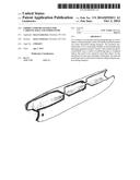
2. The moderately flexible handle-grip/hand grip apparatus is purposely cut to roughly 4 inches long which is intended to be cut wider than most hands in order to counter-act the pressure produced from holding weighted bags. The material cut is from sturdy yet pliable tubing that produces a slight upward "U" shaped curve (as depicted in FIG. 7) as opposed to the slight downward "U" shaped curve of other bag handle-grips such as Pat. No. D624411 or straight-shaped devices such as patents Pat. No. D436036, U.S. Pat. Nos. 5,738,401, 7,387,324. The slight upward U shaped curve is intentionally produced to help counter the downward weight of a loaded bag or package that creates a downward "V" shape pressure to the hand. The width of the tubular material and the effect of the slight upward U shaped curve at that width in addition to the combination of vinyl and foam rubber produces a superior counter-action to the downward pull of a weighted bag or other object.
Description:
[0001] The handle-grip/hand grip apparatus (named Grripz® comfort
handle®) are made from vinyl tubing (comes in one and two layers)
material as well as colored PVC poly urethane alloy (two layers) tubing
material. The tubing is first cut to roughly four inches long. Additional
cutting to the top of the roughly four inch vinyl tubing is done to
produce an opening to the outer face of the tubing as well as create
unique separated flexible protrusion or protrusions located on two
opposing sides or one side (depending on the design) of the apparatus as
seen in FIGS. 1, 2, 3, 5, 8, 9, 10, 11, 12, 13, 14, 15, 16, 17, 18, and
19. The protrusion(s) allow a person to push bag handles beyond the
protrusion(s) and into the apparatuses tubular recess. This also allows
the grip to remain on the bag because of these protrusion(s) and the
flexibility of the protrusion(s) allow bag handles to be easily removed
from the tubular recess. The tubing is cut to intentionally produce
handle-grips/hand grips that curve upward (not downward) to form a slight
"U" shape (as depicted in FIG. 7). The reason for this is to help counter
the downward weight of a loaded bag that will be carried in order to
provide more support for the hand carrying the weight. This helps reduce
stress applied to the finger-joints and reduces the cutting off of
circulation that occurs when carrying weighted bags with flat and narrow
handle-loops. Short notches are cut at each end of the roughly four inch
handle-grip/hand grip apparatus that act as a guide just prior to
beginning of insertion of bag loops into the apparatuses interior. These
notches can be seen in "a" and "b" of FIG. 3 (top view) and "a" and "b"
in FIG. 6 (bottom view).
[0002] The handle-grip/hand grip apparatus (named Grripz® comfort handle®) can hold a key ring, are pocket sized, portable, light, and made from a comfortable material (not hard like wood or plastic, yet more supportive than foam alone or silicone alone) that is pliable and economical to both the producer and buyer. A foam rubber layer can be (and has been) installed to the exterior of the handle-grip/hand grip apparatus as seen in FIG. 8, thereby extending the tubular contour for added comfort. The apparatus can carry one bag (varying in bag types from leather to paper, plastic or fabric) or multiple shopping bags (paper, plastic or reusable/recycled) as well as a variety of other materials used for carrying objects. The length of the bottom of the handle-grip/hand grip apparatus from end notch to end notch as seen in FIG. 6 is intentionally cut to a length that is slightly wider than the width of a hand in order to combat finger-joint stress and the narrowing affect on the hand and cutting off of circulation that bag handles produce when a bag is loaded with a certain amount of weight. The tubular shape of the handle-grip/hand grip apparatus provides a superior contour for the hand and fingers to touch as opposed to rectangular shaped devices with ninety degree angles and allows for freer finger movement then if indentures were made to fit each finger.
[0003] The handle-grip/hand grip apparatus for bag carrying became available publicly as of Apr. 22, 2011 in-person in Union Square Park in New York City and online at http://grripz.com
DRAWINGS
[0004] FIG. 1 is an upper diagonal view of the hand grip device
[0005] FIG. 2 is another upper diagonal view of the hand grip device with added web address
[0006] FIG. 3 is a top view of the hand grip device
[0007] FIG. 4 is a front-side view looking into the tubular device as if looking through a tunnel
[0008] FIG. 5 is a slight variation of the previous diagonal views seen in FIGS. 1 and 2
[0009] FIG. 6 is a bottom view of the hand grip device
[0010] FIG. 7 depicts the intentional slight "U" shape of the apparatus
[0011] FIG. 8 is the hand grip device with additional exterior layer of foam rubber for added comfort and stability
[0012] FIG. 9 is a variation of the flexible protrusion(s) used in the design of the outer face of the hand grip device
[0013] FIG. 10 is a variation of the flexible protrusion(s) used in the design of the outer face of the hand grip device
[0014] FIG. 11 is a variation of the flexible protrusion(s) used in the design of the outer face of the hand grip device
[0015] FIG. 12 is a variation of the flexible protrusion(s) used in the design of the outer face of the hand grip device
[0016] FIG. 13 is a variation of the flexible protrusion(s) used in the design of the outer face of the hand grip device
[0017] FIG. 14 is a variation of the flexible protrusion(s) used in the design of the outer face of the hand grip device
[0018] FIG. 15 is a variation of the flexible protrusion(s) used in the design of the outer face of the hand grip device
[0019] FIG. 16 is a variation of the flexible protrusion(s) used in the design of the outer face of the hand grip device
[0020] FIG. 17 is a variation of the flexible protrusion(s) used in the design of the outer face of the hand grip device
[0021] FIG. 18 is a variation of the flexible protrusion(s) used in the design of the outer face of the hand grip device
[0022] FIG. 19 is a variation of the flexible protrusion(s) used in the design of the outer face of the hand grip device
User Contributions:
Comment about this patent or add new information about this topic:
Images included with this patent application:
 |  |
 |  |
| Similar patent applications: | |
| Date | Title |
|---|---|
| 2014-10-16 | Low profile lifting assembly for managing electrical components during installation and service of machines |
| 2014-09-25 | Micro-nano tools with changeable tips for micro-nano manipulation |
| 2014-09-18 | Ladder carrying handle |
| 2014-10-16 | Spring retained end effector contact pad |
| 2014-09-18 | Container retaining device |
| New patent applications in this class: | |
| Date | Title |
|---|---|
| 2011-11-03 | Device for the manual transportation of loads |
| 2010-03-04 | Comfort grip for bag handles |
| 2008-11-27 | Hand tool for bundling plastic bags |
| Top Inventors for class "Handling: hand and hoist-line implements" | |
| Rank | Inventor's name |
|---|---|
| 1 | Kenjiro Murakami |
| 2 | Giuseppe Maffeis |
| 3 | Ghee Hua Ng |
| 4 | Nicholas Roy Corson |
| 5 | Giuseppe Maffeis |