Patent application title: Propeller Saver Bracket
Inventors:
Edgar Scott Smith (Virginia Beach, VA, US)
IPC8 Class: AA63H2304FI
USPC Class:
446163
Class name: Aquatic boat having propulsion means
Publication date: 2014-08-21
Patent application number: 20140235134
Abstract:
The invention is a bracket designed to save propellers, drive shafts,
drive dogs and propeller nuts from falling off and sinking to the bottom
of the water, when a drive shaft fails on a model boat. The means is
achieved by a propeller saver bracket that is easily attached and removed
from all types of existing boat drive system set ups, and also provides
the boat with the unexpected improved benefits of greater high speed
stability and steering.Claims:
1. A propeller saver bracket secured to a propeller powered model boat,
wherein the propeller saver bracket is configured so that it extends out
from the boat, beyond the propeller and is located directly behind the
propeller.
2. The propeller saver bracket of claim 1, wherein the bracket is a monolithic piece.
3. The propeller saver bracket of claim 1, wherein the bracket is rigidly mounted to the boat so that it is immovable during boat operation.
4. The propeller saver bracket of claim 1, wherein the bracket is made of metal.
5. The propeller saver bracket of claim 4, wherein the metal is stainless steel.
6. The propeller saver bracket of claim 4, wherein the metal aluminum or aluminum alloy.
7. The propeller saver bracket of claim 1, wherein the bracket is made of a polymeric material or carbon fiber.
8. The propeller saver bracket of claim 1, wherein the propeller saver bracket is secured to propeller strut brackets.
9. The propeller saver bracket of claim 1, wherein the propeller saver bracket is secured to propeller saver mounts that are secured to the boat.
10. The propeller saver bracket of claim 1, wherein the bracket extends out above a propeller shaft and once beyond the propeller extends downward so as to be situated directly behind the propeller.
11. The propeller saver bracket of claim 1, wherein the bracket further comprises a water pick up tube.
Description:
BACKGROUND OF THE INVENTION
[0001] 1. Field of Invention
[0002] The present invention includes embodiments described herein generally relating to brackets that extend out beyond the propeller and sit directly behind the propeller shaft, so that if a flexible propeller shaft should break, the propeller and shaft parts will remain attached to the boat and not be lost.
[0003] 2. Description of the Related Art
[0004] Remote controlled model boats are powered by electric or gas motors. These motors spin a drive shaft that in turn spins the propeller to move the boat through the water. Drive shafts come in many sizes and designs. Specifically a straight drive is considered by many to be the most efficient in transferring energy from the motor to the propeller as the straight drive shaft will only have two points of low friction, one at the motor and one at the propeller. Motors are mounted inside the boat so that they are typically above the water line and the propellers are located below the boat, so as to be below the surface of the water. The straight shafts thus do not and cannot be designed to transfer thrust parallel with the boat and the plane of the water and thus angles the thrust in a downward direction. When the propeller is angled downward the thrust is also angled downward which robs the boat of speed due to the downward force on the bow. To be most efficient the propeller should be facing the rear of the boat perpendicular to the boat when on plane with the water. Designs to angle the straight shaft to provide the thrust towards the rear of the boat, include adding u-joints and gears within the shaft. These added joints create more friction and pressure points to the drive shaft and thus are causes for lost efficiency especially in a high performance drive system. Further problems encountered with straight shafts include less adjustability. With a straight shaft the motor and strut locations need to be precisely controlled. If they are not located in the correct position the boat will vibrate to the point where u-joint failures drastically increase and the boat is rendered not drivable.
[0005] Most remote controlled model boats utilize a flexible drive shaft instead of a straight drive shaft. The flexible drive shaft allows for greater range of motor placement inside the boat. The shaft curves inside the hull and allows for the propeller to be aligned parallel to the boat hull regardless of where the motor is located within the boat. This curve in the flexible shaft also allows the motor to be mounted inside the boat at a level above the water line preventing water from flowing past the shaft and into the boat.
[0006] The flexible drive shaft starts at the motor and extends out the rear of the boat through a tube or shaft housing and is held in proper alignment by a propeller strut or a shaft strut (12). Beyond the strut is located a drive dog (15) which turns the propeller (14) that is held on the end of the flexible shaft by a propeller nut or collet (13). If the flexible shaft is not mounted properly and routinely lubricated, it is prone to failure when revved at high speeds by the motor. When the flexible shaft breaks, the shaft will snap and slide out the back of the propeller strut (12) taking with it the drive dog (15) propeller (14) and collet (13). Propellers are often balanced and sharpened in a painstaking task, which is not only time consuming but also expensive. A balanced and sharpened propeller (14) is costly and replacing the shaft, propeller and collet due to the flexible shaft breaking can create a reoccuring cost and wasted time to the user.
[0007] What is needed is a means for keeping the flexible shaft (11) in the propeller or shaft strut (12) even if the flexible shaft is to snap or break. This allows for the boat to be retrieved without losing the drive dog (15) the propeller (14) and the collet (13).
[0008] In the art and provided by the present invention is a means for saving drive shafts, propellers, dog drives, and propeller nuts, from falling off and sinking to the bottom of the water when a drive shaft fails. The means is achieved by a propeller saver bracket that is easily attached and removed from all types of existing boat set ups with only a wrench. The propeller saver also provides the boat with the unexpected improved benefits of greater high speed stability and steering.
BRIEF SUMMARY DISCUSSION OF INVENTION
[0009] For a further understanding and nature and objects of the present invention reference should be made to the following detailed description, taken in conjunction with the accompanying drawings, in which like elements are given the same or analogous reference numbers and wherein:
LIST OF FIGURES
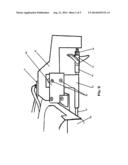
[0010] FIG. 1 is a drawing showing one propeller saver bracket design of the present invention mounted to a particular propeller strut of a particular boat.
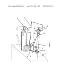
[0011] FIG. 2 is a drawing showing an alternative propeller saver bracket of the present invention mounted to a particular propeller strut of a particular boat.
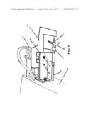
[0012] FIG. 3: is a drawing showing an alternative propeller saver bracket of the present invention mounted to a particular propeller strut of a particular boat.
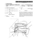
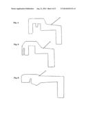
[0013] FIG. 4 is a drawing showing the propeller saver bracket used in FIG. 1.
[0014] FIG. 5 is a drawing showing the propeller saver bracket used in FIG. 2.
[0015] FIG. 6 is a drawing showing the propeller saver bracket used in FIG. 3.
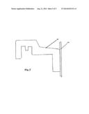
[0016] FIG. 7 is a drawing showing the propeller saver bracket of the present invention which includes the water pick up tube.
DESCRIPTION OF THE PREFERRED EMBODIMENTS
[0017] By way of example, and in accordance with the present invention, a novel bracket is provided. This bracket is mounted to a remote controlled model boat which allows the propeller, drive dog, and propeller collet to be retained in case of a drive shaft failure.
[0018] Typical remote controlled boat designs can be seen in FIGS. 1-3. The remote controlled boats may be powered by a gas or an electric motor which is not shown for simplicity of the drawing. The external drive components of a remote controlled boat is at the rear (10) and consists of a drive or propeller shaft inside a protective shaft tube which may or may not be lined in Teflon (11). The drive shaft inside the shaft tube (11) is connected to the motor, and spins at very high revolutions to power the boat in a forward or backward direction. The propeller shaft inside shaft tube (11) typically consists of a drive dog (15) which drives the propeller (14). The propeller (14) is held against the drive dog (15) by a propeller nut or collet (13). The drive shaft inside the shaft tube (11) may be a flexible drive shaft or a combination flex and rigid drive shaft.
[0019] As seen in FIGS. 1-3, the drive shaft tube (11) is typically held in place by a propeller strut or shaft strut (12) which is either directly attached to the boat, or may be attached to the boat by strut brackets (20). The propeller strut (12) allows proper alignment of the propeller (14) in the water, to ensure that the thrust of the propeller is parallel with the hull and thus creating the desired "on plane" condition. As seen in FIGS. 1-3, the remote controlled boat designs further comprise a rudder (3) which is separate from the propeller strut (12) and is used to control and steer the boat through the water.
[0020] The design of the propeller saver bracket (17) may be any which allows for it to be mounted to the rear of the boat (10) the strut brackets (23) or the propeller strut (12) and protrudes beyond the propeller (14) to a desired distance which is determined based on desired clearance from the propeller (14) and/or collet (13)shaft end. It is configured with a depth that allows the bracket to be situated directly behind the propeller (14) or collet (13) thereby maintaining the ability to keep the drive shaft from falling out and sinking to the bottom in case of a propeller shaft failure.
[0021] As seen in FIGS. 1-3, the propeller strut (12) is held to the boat by strut brackets (20) and a mechanical fastening system (21). This mechanical fastening system (21) is used to secure the strut brackets (20) in such a manner that they hold and secure the propeller strut (12) in place. The propeller saver bracket (17) may be added to the stock propeller strut, by simply loosening the mechanical fastening means (21) and inserting the propeller saver bracket (17) thereon and retightening the mechanical fastening means (21).
[0022] As seen in FIG. 3, this particular remote controlled model boat contains strut brackets (20) similar to the boat designs seen in FIGS. 1 and 2, however they are not configured in a way to accommodate for the propeller saver bracket (17) to be aligned with the center point of the propeller and attached thereto. In these cases where the strut brackets (20) are not configured to accommodate the proper alignment of the propeller saver bracket (17) the propeller saver bracket (17) may be supplied with propeller saver bracket mounts (23) which attach to the boat at the same location where the strut brackets (20) are attached. These propeller saver bracket mounts (23) allow for greater surface area for gripping the propeller saver bracket (17) to ensure that it stays in place during operation. While in this embodiment, the propeller saver bracket mounts (23) are attached to the boat through the mounts used to attach the strut brackets (20). One can easily modify the boat so that the propeller saver bracket mounts (23) are attached directly to the boat if desired.
[0023] As seen in FIG. 1, a threaded hole may be drilled into one or both of the stock strut brackets (20) and a set screw (19) may be tightened against the propeller saver bracket (17) in order to keep the bracket in place during operation. While a set screw has been exemplified in this embodiment, a through hole may alternatively be utilized so that a nut and bolt system may be used. While in the preferred embodiment, the hole is drilled through one or both of the strut brackets (20). The hole may also be drilled through the propeller strut (12). The use of the set screw (19) or the alternative embodiments described in this paragraph are only precautionary measures to keep the propeller saver bracket attached to the boat and are not necessary to the operation and function of the propeller saver bracket. While the set screw (19) or fastening means, is only shown for FIG. 1, it is easily envisaged in FIG. 2, and is substituted in FIG. 3 for the mounting means that secures the prop saver bracket (17) to the prop saver bracket mounts (23).
[0024] The propeller saver bracket (17) can be made of any known material including metals, polymers, ceramics or even carbon fiber. The most preferred material used to make the propeller saver bracket is aluminum or aluminum alloy which combines the benefits of being resistant to rusting and also being lightweight. Also most remote controlled boats are crafted with propeller struts (12) that are made of aluminum or aluminum alloy, so that the added propeller saver bracket (17) will look like an original part of the model boat when formed of aluminum or aluminum alloy. In these regards the propeller saver bracket (17) is preferably formed of the same material and color that the propeller strut (12) is made of. Other preferred metals include stainless steel or brass, which are commonly used metals that are able to contact water and be resistant to rusting. Other preferred materials include polymeric or plastic materials which are lightweight, will not rust and also allow for ease of manufacturing. Other less preferable materials which may also be used include ceramics or carbon fiber which will not rust however will have higher manufacturing costs.
[0025] The propeller saver bracket (17) may be anodized, painted or powder coated to any color desired. The propeller saver bracket (17) may be etched or engraved with any type of logo or indicia desired. The propeller saver bracket may also be polished, hammered, sanded or brushed to provide a desired look and finish. Preferably the bracket is finished to cause the least amount of drag when slicing through the water.
[0026] The propeller saver bracket may be provided with blunt edges for ease of manufacturing, in the case of cutting or stamping a sheet of metal. However, the propeller saver bracket may also be provided with beveled edges on the edges facing the propeller and/or the edges facing away from the boat. These beveled edges allow the propeller saver bracket to slice through the water with ease, and thus reduces drag. The angle of the beveled edge, especially on the leading edge, needs to be carefully controlled so as to provide the least amount of drag while still providing the function of saving the propeller shaft in case of failure. Therefore, in its preferred embodiments the leading edge of the propeller saver bracket is provided with a beveled edge of 90° or less in order to maintain/maximize the ability of the propeller saver bracket to prevent the propeller shaft from sliding out of the strut housing thus saving the propeller and attaching parts from loss.
[0027] The propeller saver bracket may be manufactured by any known means. When the propeller saver bracket is made out of metal or plastic, the bracket may be manufactured by stamping, cutting, CNC machining, or laser cutting. When the propeller saver bracket is made of ceramic, methods of manufacturing may include hot pressing, cold isostatic pressing, or sintering methods.
[0028] An unexpected advantage of adding the propeller saver bracket (17) to the rear of the boat is that it provides the boat with vastly improved cornering at any speed but particularly at high speeds. The propeller saver bracket (17) also reduces the tendency to skid during high speed turning or cornering and will give the user much improved maneuverability and cornering, which translates to faster run times during competitive racing.
[0029] The propeller saver bracket is preferably a monolithic, unibody piece, however may be made of several pieces attached by known fastening means. The propeller saver bracket is meant in its preferred embodiments to be rigidly attached to the boat, and will not function as a moving rudder, rather as a rigid rudder that provides enhanced stabilization while serving the function of saving the propeller, shaft and associated parts in case of failure.
[0030] As seen in FIGS. 1-3, the depth of the propeller saver bracket (17) is exemplified to be the depth of the propeller (14) or the depth of the collet (13). The propeller saver bracket may extend to any depth desired past the centerline of the propeller (14) and collet (13) and shaft end. This required depth allows the propeller saver bracket to perform its function to maintain the propeller, shaft, drive dog and collet in the boat in case of drive shaft failure. Longer depths beyond the propeller allow for greater sta bilization.
[0031] FIGS. 4-6, show the specific bracket configurations for the brackets shown in FIGS. 1-3, respectively.
[0032] As seen in FIG. 7, the propeller saver bracket (17) may also be used to enhance the cooling system of a model boat. Typically, the stock rudder cooling system is restrictive and less efficient by design. Cooling water is supplied to the motor through an orifice cut in one side of the rudder and then through a hose to the motor. As the boat is turned in the direction of the orifice on the rudder, water pressure is increased on that side of the rudder forcing cooling water be supplied to the motor. When turning the model in the opposite direction of the rudder orifice, the water pressure drops rapidly and the cooling water slows or stops until the boat is again turned the other direction. With the propeller saver bracket cooling system enhancement, this cooling system water starvation would not occur due to the constant water pressure on the pick up tube from the propeller at all times during left or right turns. As stated, this cooling system enhancement is accomplished by the addition of a cooling water pick up tube/tubes, 30, to the propeller saver bracket, 17. The ideal placement of the cooling water pick up tube would be on the trailing edge of the propeller saver bracket (17), which would allow a solid, unobstructed leading edge to ensure the propeller saver bracket can perform it's main function of retaining propellers. With the cooling water pick up tube being placed directly behind the propeller, it will provide increased pressure to force more cooling water to be supplied to the motor/motors. The cooling pickup tube, 30, may be attached in many ways including the use of welding, brazing, epoxy or even wire ties. Although one or more tubes could also be attached to either or both sides of the propeller saver bracket, this may introduce unwanted drag. The cooling enhancement may also be accomplished by drilling or casting a passage or passages to the leading edge or sides of the propeller saver bracket. While FIG. 7 shows a water cooling tube on only one of the bracket designs, one of ordinary skill in the art can easily envisage using it on any of the brackets designed based on the instant invention.
[0033] While the preferred embodiments and figures show the propeller saver bracket (17) mounted above the propeller struts and above the water line, the propeller saver brackets may be mounted on either side of the propeller struts or on the side of the boat or mounted underneath the boat or propeller strut (12) so that it is completely submerged under the water when in use. These types of designs may also provide increased stability; however, may also introduce drag.
[0034] While single propeller engines are shown in the figures, the design is equally effective for twin propeller engines, or any number of engines and propellers used, where a propeller saver bracket (17) can be mounted to protect each propeller/drive shaft system used.
[0035] While preferred embodiments of the foregoing have been shown and described it will be understood by one of routine skill in the art that the description is illustrative and not intended to limit the scope or purpose of the invention. FIGS. 1-3, show three specific boats for three separate manufacturers; however, the scope is not limited to these three manufacturers and boat models. The propeller saver bracket is easily designed to fit any boat type and any boat manufacturer as desired.
User Contributions:
Comment about this patent or add new information about this topic:
Images included with this patent application:
 |  |
 |  |
 |  |
| Similar patent applications: | |
| Date | Title |
|---|---|
| 2010-08-05 | Self-propelled water toy |
| 2014-09-11 | Plush toy for mounting on a vertical surface |
| New patent applications in this class: | |
| Date | Title |
|---|---|
| 2011-03-31 | Water vessel using self-propelled water wheel |
| Top Inventors for class "Amusement devices: toys" | |
| Rank | Inventor's name |
|---|---|
| 1 | Robert H. Mimlitch, Iii |
| 2 | David Anthony Norman |
| 3 | Michael Nuttall |
| 4 | Stacy Lynn O'Connor |
| 5 | Joel Reagan Carter |