Patent application title: DIFFERENTIAL BEVEL GEAR SPEED REDUCER
Inventors:
Karen Park (Los Angeles, CA, US)
Dong Soo Oh (Seoul, KR)
IPC8 Class: AF16H4808FI
USPC Class:
475230
Class name: Planetary gear transmission systems or components differential planetary gearing bevel gear differential
Publication date: 2014-08-07
Patent application number: 20140221147
Abstract:
The present invention relates to a high speed reduction power transfer
device. The differential planetary speed reducer currently in use uses
modified teeth gear, which makes precision processing difficult, causes
many problems associated with noise during operation, wear by friction,
reduced efficiency, etc. and reduces durability.
The present invention is only formed of combined standard type Bevel
gears, making it easy to design and process gears and solving the
fundamental problems associated with the conventional gears. With the
potential of supplying mass-produced volume at low costs, the present
invention will be able to promptly meet the demand for the speed reducers
whose demand is rapidly increasing.Claims:
1. A differential Bevel gear speed reducer only formed of standard type
gears having same gear module and teeth with three identical pinion Bevel
gears (31) engaged equidistantly in between the input Bevel gear (15) and
the output Bevel gear (21) in a structure under the condition that (i)
gear module is the same, (ii) teeth are the same, (iii) the pitch cone
angle of all the Bevel gears is 90.degree. and the cone apexes meet at
one point, and (iv) the number of teeth on the counterpart gear must
maintain an odd-and-even number relationship so that the rotational axis
of the gear lies on the same plane and three pinion Bevel gear axes (30)
slant-crosses the input and output Bevel gear axes, wherein
revolution-inducing Bevel gears (32) having the same number of teeth,
module, and cone apex as the pinion revolution Bevel gear (31) are
fixed-installed on the outside of said pinion Bevel gear axis (30), and
the orbit Bevel gear (42) that is engaged thereto is fixed-installed on
the inside of the housing (30), thereby enabling the pinion Bevel gear
(31) to start revolving, as the input Bevel gear (15) revolves, following
the orbit Bevel gear (42) along with the revolution-inducing Bevel gear
(32) and, upon one rotation of the input Bevel gear (15), the output
Bevel gear (21) to differentially rotate by as much as the difference in
the number of teeth between the input and output gearsDescription:
FIELD OF ART
[0001] The present invention relates to a differential gear speed reducer.
BACKGROUND ART
[0002] Currently, high speed reduction rotating power devices are generally classified into worm speed reducers and differential planetary gear speed reducers. With a simple structure, a worm speed reducer is easy to manufacture. But it has problems such as friction-induced wearing and heating, low efficiency, and durability, which limits the scope of its use. A differential planetary speed reducer uses a gear with modified teeth whose amount of profile shift (or the coefficient of profile shift) was adjusted, which causes problems associated with noise, wear, and durability and thus makes precision processing difficult.
<Note: See glossary for profile shift amount and profile shift coefficient>
DESCRIPTION OF THE INVENTION
[0003] In order to solve various problems that occur as current differential planetary gear speed reducer uses a profile shifted gear by adjusting the profile shift amount, it is the object of the present invention to manufacture a differential gear speed reducer made of only standard type gears, thus making it easy to design and processing the gears and fundamentally solve the problems with the current planetary gear speed reducer.
Technical Problems to be Solved by the Present Invention
[0004] In a differential planetary gear speed reducer, two different gears having different number of mutually engaging teeth have the center of pitch circle fixed. Thus, in order to adjust the circumference of the pitch circle, it is unavoidable to adjust the amount of profile shift or the coefficient of profile shift. However, the present invention makes the centers of the pitch circles of two engaging gears different, thereby manufacturing a differential speed reducer composed of a combined structure in which standard gears with same module and teeth meet the requirements of mutual engagement without having to adjust the amount of profile shift or the coefficient of profile shift.
Means of Solving the Problems
[0005] It is to convert the current structure of fixed center of rotation of differential planetary gears into a Bevel gear combination structure in which the centers of pitch circles of two engaging gears are different and the circumference of each gear is set differently.
[0006] Three Bevel gears having different number of teeth are made to have the same module and teeth with the axis of rotation lying on the same plane as the mutual engagement condition, thus allowing them to rotate differently by as much as the difference in the number of teeth.
Effect of the Invention
[0007] It achieves high efficiency, lowers noise and improves durability as required by the industrial automation devices and various control devices. Only composed of standard type gears easy to design and process, it enables to supply mass production volume at low costs.
BRIEF DESCRIPTION OF THE DRAWINGS
[0008] FIG. 1--A longitudinal cross-section of the present invention
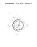
[0009] FIG. 2--A latitudinal cross-section of the present invention
[0010] FIG. 3--Construction of a pitch circle and the direction of axis rotation
DETAILED DESCRIPTION FOR IMPLEMENTING THE INVENTION
[0011] Primary speed reduction, which is a speed reduction based on the proportion of the number of teeth, by the planetary gear is combined with secondary speed reduction, which is a differential speed reduction based on the difference in the number of teeth according to the present invention for high speed reduction for high speed reduction.
[0012] As illustrated in FIG. 1, FIG. 2, and FIG. 3, the differential gear speed reducer based on the difference in the number of teeth, according to the present invention, has an operational structure in which three identical pinion Bevel gears (31), which have pitch cone angle of 90° with the cone apex at one point in the middle, engage and rotate in revolution between two input Bevel gears (15) having different number of teeth and the output Bevel gear (21) to perform a sun-and-planet motion.
[0013] To begin with, the speed of said input Bevel gear (15) is reduced primarily based on the proportion of the number of teeth of the planetary gear as illustrated in FIG. 1.
[0014] The cone apex of three pinion Bevel gears (31) lies on the extended line of the rotational axis of the output Bevel 21 and the rotational axis of the input Bevel gear 15. The extended line of the pinion Bevel gear (30) slant-crosses the input and output rotational axes.
[0015] The conditions of engagement among the pinion Bevel gear (31), input Bevel gear (15) and output Bevel gear (21) are: (i) module must be the same, (ii) teeth are the same, (iii) the number of teeth on the counterpart gear must maintain a odd-and-even number relationship so that the rotational axis of the gear lies on the same plane, and (iv) the pitch cone angle of all the Bevel gears is 90° and the cone apex must meet at one point.
[0016] A revolution-inducing gear (32) having the same module, same number of teeth, and same cone apex as the pinion Bevel gear (31) is fixed-installed on the outside of the pinion Bevel gear (31) to revolve together.
[0017] An orbit Bevel gear (42) that is engaged to said orbit-inducing Bevel gear (32) is fixed-installed inside the housing (40) has the same module, teeth and cone apex for engagement to the orbit-inducing Bevel gear (32). Thus, it plays a role of a rotation orbit of a revolution-inducing Bevel gear (32).
[0018] The sizes of mutual pitch circuit diameter (D) of all the gears must be D3<D2<D1≦D4 as illustrated in FIG. 3.
* Outside pitch circle is taken as the reference line.
[0019] Differential speed reduction ratio can be displayed as follows:
Speed reduction ratio = Input Bevel gear pitch circle diameter ( D 1 ) - Output Bevel gear pitch circle diameter ( D 2 ) Output Bevel gear pitch circle diameter ( D 2 ) ##EQU00001##
[0020] If module=1 and diameter=D, from m0=D/No. of teeth, No. of teeth=D. Thus,
Speed reduction ratio = No . of input Bevel gear teeth - No . of output Bevel gear teeth No . of output Bevel gear teeth ##EQU00002##
[0021] Spiral Bevel gear are more effective in preventing the occurrence of thrust caused by revolving pinion Bevel teeth.
[0022] As the input Bevel gear (15) revolves, the pinion Bevel gear (31) starts revolving following the orbit Bevel gear (42) along with the revolution-inducing Bevel gear (32). And, during 1 rotation, it causes differential rotation of the output Bevel gear (21) by as much as the difference in the number of teeth between the input Bevel gear (15) and the output Bevel gear (21).
[0023] In FIG. 3, the pitch cone angle of all the gears is 90° and the cone apex meets at one point. If the input Bevel gear (15) rotates clockwise, the output Bevel gear (21) differential-rotates counterclockwise by as much as the difference in the number of teeth, while the pinion Bevel gear (31) rotates counterclockwise and revolves clockwise riding the orbit Bevel gear (42).
[0024] The internal space of the housing (40) is replete with lubricating oil, enabling to prevent wear and noise and perform cooling operation.
EXPLANATION FO REFERENCE NUMERALS
[0025] 10 Input axis
[0026] 11 Sun gear
[0027] 12 Planetary pinion gear
[0028] 13 Planetary pinion gear axis
[0029] 15 Input Bevel gear
[0030] 20 Output Bevel gear axis
[0031] 21 Output Bevel gear
[0032] 30 Pinion Bevel gear axis
[0033] 31 Pinion Bevel gear
[0034] 32 Revolution-inducing Bevel gear
[0035] 40 Housing
[0036] 41 Fixed internal gear
[0037] 42 Fixed orbit Bevel gear
Glossary
[0037]
[0038] m0 Gear module
[0039] D Pitch circle diameter of a gear
[0040] D1 Input Bevel gear pitch circle diameter
[0041] D2 Output Bevel gear pitch circle diameter
[0042] D3 Pinion Bevel gear pitch circle diameter
[0043] D4 Orbit Bevel gear pitch circle diameter
[0044] O Bevel gear cone apex
[0045] <Note> (1) Amount of profile shift: Distance between the standard pitch line of a rack and the standard pitch line of a gear (2) Coefficient of profile shift: The amount of profile shift divided by Modulus
User Contributions:
Comment about this patent or add new information about this topic:
Images included with this patent application:
 |
| Similar patent applications: | |
| Date | Title |
|---|---|
| 2009-09-03 | High ratio gear reducer |
| 2010-02-11 | Lever-type gear reducer |
| 2014-10-16 | Differential gear |
| 2014-10-16 | Differential gear |
| 2014-10-16 | Differential gear |
| New patent applications in this class: | |
| Date | Title |
|---|---|
| 2022-05-05 | Drive unit assembly |
| 2018-01-25 | Cross-shaft for three pinion differential |
| 2016-12-29 | Differential gear assembly |
| 2016-06-16 | Differential device |
| 2016-06-09 | Differential device |
| New patent applications from these inventors: | |
| Date | Title |
|---|---|
| 2014-12-18 | System, method, and computer-readable recording medium for providing dual mode weapons in an online first personal shooter game |
| Top Inventors for class "Planetary gear transmission systems or components" | |
| Rank | Inventor's name |
|---|---|
| 1 | James M. Hart |
| 2 | Scott H. Wittkopp |
| 3 | Andrew W. Phillips |
| 4 | Clinton E. Carey |
| 5 | Andrew W. Phillips |