Patent application title: HYPODERMIC SYRINGE ASSIST APPARATUS AND METHOD
Inventors:
Renee Joyal (Tynsboro, MA, US)
David Moxlow (Grosse Ile, MI, US)
David H. Safavian (Alexandria, VA, US)
IPC8 Class: AA61J120FI
USPC Class:
533811
Class name: Package making means to open or erect receptacle
Publication date: 2014-07-31
Patent application number: 20140208689
Abstract:
A hypodermic syringe assist device and method for effectively assisting
individuals lacking full use of both hands and/or those having movement
or visual disorders with safely and accurately withdrawing an injectable
pharmaceutical drug or medicine from variously sized medicine vials
includes a body having first and second spaced portions and configured to
receive a medicine vial there between and a variety of adjustable size
inserts for securely receiving the vial in the body such that medicine
may be safely withdrawn from the vial using a hypodermic syringe by such
an individual. The assist device includes a plurality of adjustable
suction cups for securing the assist device in a variety of locations and
positions as well as an adjustable magnifier for use by the individual in
better observing the vial and withdrawing medicine there from using a
hypodermic syringe.Claims:
1. An apparatus for use in withdrawing medicine from a vial using a
hypodermic syringe, the medicine vial including an end including a
septum, the apparatus comprising: a body having a first portion and a
second portion spaced from the first portion and configured for receiving
the vial to be held by the first and second portions; a first insert
located in a first recess in the first portion; a second insert located
in a second recess in the second portion; a coupler having a first end
connected to the body and a second end for selectively coupling the
apparatus to a generally stationary object; and wherein the second
portion of the body and the second insert each include aligned holes for
receiving and fixing the end of the medicine vial with respect to the
body such that a user may insert the needle of the hypodermic syringe
through the hole in the second portion and into the vial.
2. The apparatus of claim 1 wherein each of the first and second inserts are configured to match a particular size medicine vial.
3. The apparatus of claim 2 wherein the body includes a channel configured to receive a first end of the coupler for coupling the coupler to the body.
4. The apparatus of claim 3 wherein the second end of the coupler comprises a suction cup configured to couple the apparatus to a surface.
5. The apparatus of claim 4 further comprising a second coupler having a first end for coupling to the body and a second end configured for selectively coupling the apparatus to a surface and wherein the first and second couplers are configured to limit movement of the apparatus to zero degrees of freedom once it is coupled to a surface.
6. The apparatus of claim 3 wherein the body includes a plurality of channels configured on the body to provide additional locations for the coupler to be connected to the body.
7. The apparatus of claim 1 including a magnifier coupled to the base and movable between a first position and a second position.
8. The apparatus of claim 7 wherein the magnifier is pivotably coupled to the second portion of the base and is configured to move to the first position aligned with the vial between the first and second portions of the base and the second position aligned below the second portion.
9. An apparatus for use in withdrawing medicine from a vial using a hypodermic syringe, the medicine vial including an end including a septum, the apparatus comprising: a body having a first portion and a second portion spaced from the first portion and configured for receiving the vial to be held by the first and second portions and wherein the body includes a channel for coupling the apparatus to a flat surface; a first insert member located in a first recess in the first portion; a second insert member located in a second recess in the second portion; wherein the first and second insert members are configured to match a particular size vial; a coupler having a first end connected to channel of the body and a second end for selectively coupling the apparatus to a flat surface; and wherein the second portion of the body and the second insert each include aligned holes for receiving and fixing the end of the medicine vial with respect to the body such that a user may insert the needle of the hypodermic syringe.
10. An apparatus for use in withdrawing medicine from a vial using a hypodermic syringe, the medicine vial including an end including a septum, the apparatus comprising: a body having a first portion and a second portion spaced from the first portion and configured for receiving the vial to be held by the first and second portions; a first insert located in a first recess in the first portion; a second insert located in a second recess in the second portion; a coupler having a first end connected to the body and a second end for selectively coupling the apparatus to a generally stationary object; a magnifier coupled to the base and movable between a first position and a second position; and wherein the second portion of the body and the second insert each include aligned holes for receiving and fixing the end of the medicine vial with respect to the body such that a user may insert the needle of the hypodermic syringe through the hole in the second portion and into the vial.
11. The apparatus of claim 10 wherein the magnifier is pivotably coupled to the second portion of the base and is configured to move to the first position aligned with the vial between the first and second portions of the base and the second position aligned below the second portion.
Description:
CROSS REFERENCE TO RELATED APPLICATION
[0001] This application claims priority to and the benefit of U.S. Provisional Patent Application No. 61/756,612, filed Jan. 25, 2013, entitled Hypodermic Syringe Assist Apparatus And Method, in the name of Rene Joyal, the entire contents of which are incorporated by reference herein for all purposes.
FIELD
[0002] The present disclosure and invention relate generally to an apparatus for use in assisting a person with removing a medication from a vial to be injected in a host. More particularly, the present disclosure relates to an apparatus and a method of use for holding a vial containing a fluid, such as a medication, and assisting a user that may be visually and/or movement-impaired to withdraw the fluid, such as an injectable pharmaceutical medication, from the vial.
DISCUSSION OF RELATED ART
[0003] Extracting a liquid (such as a pharmaceutical medication) from a vial or bottle into a hypodermic syringe can be a complex operation even for a person having excellent motor skills, control and acumen. It is necessary to maintain a sterile field during such procedures, necessitating the use of sterile gloves and sterile equipment. The septum of certain multi-use vials or bottles can be sterile, while the exterior surface of the same multi-use bottle may not be sterile. Handling the non-sterile exterior surface of bottles during a sterile procedure can require the assistance of another person or the use of multiple layers of gloves. Known options are expensive, cumbersome and time-consuming. An apparatus that holds the bottle in a proper position eliminates these expensive options and enables the practitioner to use both hands in a sterile fashion without additional assistance.
[0004] It is generally known to use a syringe guide for use in facilitating the filling of the syringe with the medicine from in the bottle. While syringe guides are generally known to help align the syringe needle with the cap of the medicine file, the known syringe guides are premised on the user having to hands and excellent fine motor skill and control. In addition, the construction of some prior art syringe guides sale to easily allow extraction of the medicine or complete extraction of all of the medicine from the medicine file. Additionally, some known syringe guides are particularly disadvantageous because they do not allow the user to easily observe the syringe while in the syringe guide and removing the medicine from the medicine file. Such known prior art syringe guides can have difficulty with proper dosage and usage. Such known syringe guides can also be difficult to keep clean and tend to result in spills of the medicine on the syringe guide. Such drawbacks can make use of the known syringe guide quite burdensome and difficult as well as resulting in additional costs and limitations of use. Despite the long felt need for such a device, none exists.
[0005] The generally known devices secure the pharmaceutical vial using a clamp, chemical adhesive, hook & loop tape or other similar device that may not be easily relocated and/or used and/or may not accommodate vertical and horizontal vial mounting positions.
[0006] The generally known devices do not accommodate various-sized vials and they may not be easily secured or removed from mounting locations. Further, they cannot offer vertical and horizontal orientations for accommodating user preferences and/or requirements and they do not have any mechanism to assist the user in reading the vial label and its dosage instructions and the dosage markings on the syringe to be filled with the pharmaceutical drug or medication in the vial.
[0007] For individuals without full, steady use of both hands, it may be nearly impossible to safely or securely hold a vial of medication and withdraw the proper dosage using a hypodermic syringe required for injecting the medication. This may be particularly true for those who have lost the use of an arm or hand, such as military veterans with combat injuries, and those with movement disorders such as Parkinson's disease.
[0008] There still long remains a significant need for a device to effectively assist those lacking full use of both hands and/or those having movement disorders and/or those having visual impairments, with safely and accurately withdrawing an injectable pharmaceutical drug or medicine from variously sized medicine vials.
BRIEF DESCRIPTION OF THE DRAWINGS
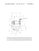
[0009] FIG. 1 is a perspective illustrative graphic of a hypodermic assist apparatus according to an exemplary embodiment of the present disclosure.
[0010] FIG. 2 is an exploded, perspective illustrative graphic view of the hypodermic assist apparatus of FIG. 1.
[0011] FIG. 3 is an alternate exploded, perspective illustrative graphic view of the hypodermic assist apparatus of FIG. 1.
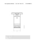
[0012] FIG. 4 is a top, plan illustrative graphic view of the hypodermic assist apparatus of FIG. 1.
[0013] FIG. 5 is a partial, side, plan illustrative graphic view of the hypodermic assist apparatus of FIG. 1.
[0014] FIG. 6 is an alternate exploded, perspective illustrative graphic view of the hypodermic assist apparatus of FIG. 1.
SUMMARY
[0015] In one exemplary embodiment there is disclosed a hypodermic syringe assist device for use in holding a medicine vial or bottle and allows easy and open access to the septum of the medicine bottle and single handed along with the ability for improved control and accuracy while filling the syringe with medicine from the vial.
[0016] In one exemplary embodiment there is disclosed a hypodermic syringe assist device that holds a medicine vial securely while providing magnification to accurately read the label and insure proper dosage. The device also provides magnification of the syringe used to inject the medicine so that the proper dosage is withdrawn from the vial and dispensed.
[0017] In one exemplary embodiment there is disclosed a hypodermic syringe assist device that can secure the vial to a flat, vertical or horizontal surface, so that the user can withdraw the proper dosage of an injectable medicine using only a single hand. The device also assists visually impaired persons by providing a magnification tool that can be used either to read the pharmaceutical vial or properly measure the dosage marks on the withdrawing syringe.
[0018] In one exemplary embodiment there is disclosed a hypodermic syringe assist device including several novel features, including utilizing suction cups that can affix the device to any hard surface, including permitting the device to be mounted either on a horizontal surface (e.g., a counter or table), or a vertical surface (e.g., a wall or bathroom mirror); the device can accept various sized vials using plastic inserts to securely hold varying dosage vials steady for the user; the device can assist the user in reading the vial and its dosage instructions and any applicable warnings contained on the vial label by using an attached magnification device; and the device can assist the user in reading the dosage markings on the syringe to be filled with the pharmaceutical by using the attached magnification device.
[0019] In another exemplary embodiment there is disclosed a hypodermic syringe assist device that incorporates a design that can be used with different sized vials and a movable magnifier that can be used by the user to more easily read either the pharmaceutical vial or the syringe.
[0020] The invention uses suction cups to easily affix the device to either a vertical or horizontal surface. The use of suction cups allows the invention to be moved quickly and easily to different locations. The invention accommodates different size pharmaceutical vials by incorporating the use of specially designed rubber inserts. The invention uses a hinged magnifier to allow the user to more easily read both the label of the pharmaceutical vial and the dosage marks on the syringe.
DETAILED DESCRIPTION
[0021] Referring in general to all of the Figures, the present disclosure and teachings described relate to, in one exemplary embodiment, a hypodermic syringe assist device or apparatus 10 may have particularly effective use in holding a medicine vial or bottle 90 and may provide for improved easy and open access to the septum of the medicine bottle 90 to provide for single-handed filling of the syringe with a pharmaceutical drug or medicine from the vial 90 along with improved control and accuracy.
[0022] Referring now to FIG. 1 there is disclosed an exemplary embodiment of a device or apparatus 10 including a base 20 that may effectively, securely hold a variety of sizes of medicine vials 90, including a standard size pharmaceutical vial 91. The base 20 may preferably be made of a plastic material, such as a medical grade material, that can secure vial 90 in a variety of orientations and locations. The base 20 includes a first generally planar and rectangular extension 21 and a second generally planar and rectangular extension 22 spaced from the first extension 21. Each of the first and second extensions 21 and 22, respectively, may include a recess and/or aperture 23 and 24, respectively as best shown in FIGS. 2, 3 and 5. As may be seen from the Figures, each recess 23 and 24, respectively, may include a first recess and a second recess having differing dimensions for use in retaining the varying inserts 70 and the vial 90.
[0023] The plastic base 20 may preferably be manufactured using either blow-molded or injection-molded plastic manufacturing technology. The channels 32 formed or made in the base 20 may be used to connect the suction cups 40 to either the vertical or horizontal surfaces of the base 20. Similarly, a channel along the leading edge of the device 10 may be formed during the production of the base 20. Alternatively, such features may be formed after making the base 20. It should be understood that the base 20 may be made from any known or existing material or any other future developed material that may be appropriate.
[0024] The base 20 may also contain a plurality of channels 32 extending along a surface thereof for use in coupling or connecting the suction cups 40 to the body 20. The channels 32 may be located at either of the vertical side or the horizontal side of the body 20. The second extension 22 of the base 20, at a leading edge thereof may also include a recess or channel for coupling, connecting and/or pivotally holding a magnifier 60 in a manner that allows the magnifier 50 to be moved or to swing up and down to permit the user to read a label on the vial and/or to permit the user to better view the syringe dosage marks.
[0025] The removable suction cups 40 may be used to affix the device 10 to either a vertical or horizontal surfaces or any angled surface in between. Each removable suction cup 40 preferably includes an extension nub, coupler or knob including a bulbous head for securing the suction cup 40 within the channel 32 and thereby the body 20 while still allowing for adjustable positioning and re-positioning of each suction cup 40 on the body 20.
[0026] The body 20 may further include an extended portion having a first surface including the recesses 32 offset or aligned at an angle of approximately 30° from the second extension 22, and a second surface offset or aligned at an angle of approximately 60° from the first extension 21 as best shown in FIG. 5. The first and second surfaces may have angles different than stated above for example, the first surface may be offset and an angle of approximately between zero and 75° and the second surface may be offset at an angle of approximately between zero and 75°. In one exemplary embodiment, the first and second surfaces may each be offset at an angle of 45°.
[0027] The magnifier 60 may preferably be an appropriately sized rectangular shaped magnifier that is usable from both sides as noted above. Along at least one edge, the magnifier 60 preferably includes a coupling mechanism or device for pivotably coupling the magnifier 60 to the body 20. The magnifier 60 as shown includes an enlarged, bulbous shaped, edge for coupling to a pivotably attached hinge member on the body 20. The pivotably attached hinge has a recess along an edge thereof for receiving the enlarged edge of the magnifier 60. The pivotably attached hinge may preferably be coupled along the leading edge of the lower extension 22 of the body 20. When the magnifier is pivotably located downward (as best shown in FIGS. 5 and 6), below the lower extension 22 of the body 20, it may be used to magnify the syringe and its indicia for more accurately filling the syringe with the medicine from the vial 90. Alternatively, the magnifier 60 may be pivotably located in an upright position such that the magnifier 60 is aligned with the vial 90 being held in the body 20 so that a user may better read the label of the vial 90.
[0028] The device 10 of the present disclosure may further include a plurality of adapters or inserts 70 which are designed and configured to match the recesses 23 and 24 of the extensions 21 and 22, respectively. One set of inserts 71 may include internal collar portions designed and configure to accommodate an industry-standard 25×54 mm vial 91. Another set of inserts 71 may include internal collar portions designed and configured to accommodate an industry-standard 20×62 mm vial 91 (as shown in FIG. 3).
[0029] The device 10 of the present exemplary embodiments and the invention embodied therein may preferably us a plastic material base 20 configured to securely hold a standard sized pharmaceutical vial, and be easily attached to a flat surface, either vertically or horizontally. For non-standard size vials, the device 10 is configured to use the rubber inserts (or collars) 70 that allow for the base 20 to hold vials that are smaller than the standard size vials. The base 20 may generally utilize two suction cups 40 to attach to a surface. By allowing the base 20 to attach to a vertical or horizontal surface, the device 10 may be configured to permit someone lacking full use of both arms & hands to safely and easily withdraw pharmaceuticals from dispenser vials. Finally, the device 10 of the exemplary embodiment of the present disclosure may use a hinged magnifier that may be moved to swing up to allow the user to clearly read the label and dosing instructions on a vial 90, or swing down to allow the user to clearly read the dosage marks on the syringe. Taken together, the components may be configured to securely hold a vial 90 so that someone without full and steady use of both hands may withdraw medicines from various sized vials to be self-injected.
[0030] In use, a person may affix the device 10 either vertically (to a wall or mirror) or horizontally (to a table or counter top) using the suction cups 40. The user would then insert the vial 91 into the inserts 71 in the recesses 23 and 24 of the base 20. With the vial 91 held by the base 20 and secured to a surface, the user may then insert the needle of the syringe into the vial 71 and withdraw the prescribed dosage with only one hand. For those with visual impairments, they may use the magnifier 60 in the "up position" to read the label on the vial 71. With the magnifier 60 in the "down" position, a visually impaired person may better read the dosage marks on the syringe. The alternate collars or inserts 71 may also be used to accommodate non-standard size vials so that they may be held in place in the base 20 as well.
[0031] Any numerical values recited herein or in the figures are intended to include all values from the lower value to the upper value in increments of one unit provided that there is a separation of at least 2 units between any lower value and any higher value. As an example, if it is stated that the amount of a component or a value of a process variable such as, for example, temperature, pressure, time and the like is, for example, from 1 to 90, preferably from 20 to 80, more preferably from 30 to 70, it is intended that values such as 15 to 85, 22 to 68, 43 to 51, 30 to 32 etc. are expressly enumerated in this specification. For values which are less than one, one unit is considered to be 0.0001, 0.001, 0.01 or 0.1 as appropriate. These are only examples of what is specifically intended and all possible combinations of numerical values between the lowest value and the highest value enumerated are to be considered to be expressly stated in this application in a similar manner. As can be seen, the teaching of amounts expressed as "parts by weight" herein also contemplates the same ranges expressed in terms of percent by weight. Thus, an expression in the Detailed Description of the Invention of a range in terms of at "`x` parts by weight of the resulting polymeric blend composition" also contemplates a teaching of ranges of same recited amount of "x" in percent by weight of the resulting polymeric blend composition."
[0032] Unless otherwise stated, all ranges include both endpoints and all numbers between the endpoints. The use of "about" or "approximately" in connection with a range applies to both ends of the range. Thus, "about 20 to 30" is intended to cover "about 20 to about 30", inclusive of at least the specified endpoints.
[0033] The disclosures of all articles and references, including patent applications and publications, are incorporated by reference for all purposes. The term "consisting essentially of" to describe a combination shall include the elements, ingredients, components or steps identified, and such other elements ingredients, components or steps that do not materially affect the basic and novel characteristics of the combination. The use of the terms "comprising" or "including" describing combinations of elements, ingredients, components or steps herein also contemplates embodiments that consist essentially of the elements, ingredients, components or steps. By use of the term "may" herein, it is intended that any described attributes that "may" be included are optional.
[0034] Plural elements, ingredients, components or steps can be provided by a single integrated element, ingredient, component or step. Alternatively, a single integrated element, ingredient, component or step might be divided into separate plural elements, ingredients, components or steps. The disclosure of "a" or "one" to describe an element, ingredient, component or step is not intended to foreclose additional elements, ingredients, components or steps.
[0035] It is understood that the above description is intended to be illustrative and not restrictive. Many embodiments as well as many applications besides the examples provided will be apparent to those of skill in the art upon reading the above description. The scope of the invention should, therefore, be determined not with reference to the above description, but should instead be determined with reference to the appended claims, along with the full scope of equivalents to which such claims are entitled. The disclosures of all articles and references, including patent applications and publications, are incorporated by reference for all purposes. The omission in the following claims of any aspect of subject matter that is disclosed herein is not a disclaimer of such subject matter, nor should it be regarded that the inventors did not consider such subject matter to be part of the disclosed inventive subject matter.
User Contributions:
Comment about this patent or add new information about this topic:
Images included with this patent application:
 |  |
| Similar patent applications: | |
| Date | Title |
|---|---|
| 2014-10-02 | Pneumatic strapping apparatus |
| 2014-11-13 | Flexible loop applicator and method |
| 2014-11-13 | Oats processing equipment and method |
| 2014-11-13 | Apparatus and method of making bio logs |
| 2014-10-02 | Multi-layer barrier film and use thereof |
| New patent applications in this class: | |
| Date | Title |
|---|---|
| 2016-07-14 | Improved apparatus for automatically opening crates of different dimensions |
| 2015-03-26 | Piercing member for container access device |
| 2014-11-13 | Disposable ampoule opener assembly |
| 2014-02-27 | Device for opening and emptying filled two-piece capsules |
| 2013-12-26 | Capsule holder for preparing a beverage |
| Top Inventors for class "Package making" | |
| Rank | Inventor's name |
|---|---|
| 1 | Donald E. Weder |
| 2 | Dennis J. May |
| 3 | Samuel D. Griggs |
| 4 | Giuseppe Monti |
| 5 | Patrick R. Lancaster, Iii |