Patent application title: HEAT DISSIPATION ASSEMBLY
Inventors:
Hsuan-I Lin (New Taipei, TW)
Assignees:
HON HAI PRECISION INDUSTRY CO., LTD.
IPC8 Class: AF28D1502FI
USPC Class:
16510421
Class name: Intermediate fluent heat exchange material receiving and discharging heat liquid fluent heat exchange material utilizing change of state
Publication date: 2014-06-26
Patent application number: 20140174699
Abstract:
A heat sink assembly includes a base, a heat pipe, a first heat sink, and
a second heat sink. The second heat sink is installed between the base
and the first heat sink. The heat pipe includes a positioning portion
sandwiched between the second heat sink and the base, and two
heat-conductive portions extending up from two opposite ends of the
positioning portion and inserted into the first heat sink.Claims:
1. A heat dissipation assembly, comprising: a base; a first heat sink
installed on the base; a second heat sink installed between the base and
the first heat sink; and a heat pipe comprising a positioning portion
sandwiched between the second heat sink and the base, and two
heat-conductive portions extending up from two opposite ends of the
positioning portion and inserted into the first heat sink; wherein the
base comprises a rectangular bracket, two spaced baffling pieces extend
up from each side of the bracket, the baffling pieces at the each side of
the bracket cooperatively bound a cutout, the heat pipe further comprises
two connecting portions respectively connected between the
heat-conductive portions and the two opposite ends of the positioning
portion, each baffling piece faces the corresponding connecting portion,
and the second heat sink is located between the cutouts of the bracket.
2. The heat dissipation assembly of claim 1, wherein the first heat sink is supported on the bracket, and a bottom of the first heat sink is engaged with the baffling pieces.
3. The heat dissipation assembly of claim 1, wherein the base further comprises a connecting member, the bracket defines an opening, the connecting member comprises a supporting plate received in the opening and two flanges extending out from two opposite ends of the supporting plate to be mounted to the bracket, the baffling pieces are respectively located at two opposite sides of the opening, and the second heat sink is mounted on the support plate.
4. The heat dissipation assembly of claim 3, wherein a top of the supporting plate defines a first receiving slot for receiving a bottom of the positioning portion of the heat pipe.
5. The heat dissipation assembly of claim 4, wherein the second heat sink comprises a bottom plate and a plurality of fins extending up from the bottom plate, the bottom plate defines a second receiving slot for receiving a top of the positioning portion of the heat pipe.
6. The heat dissipation assembly of claim 1, wherein the first heat sink comprises a plurality of fins parallel to and spaced from one another, each fin defines two inserting holes, the heat-conductive portions are inserted into the inserting holes of each fin.
Description:
BACKGROUND
[0001] 1. Technical Field
[0002] The present disclosure relates to a heat dissipation assembly.
[0003] 2. Description of Related Art
[0004] Central processing units (CPUs) of computers or servers generate a large amount of heat during operation. The heat needs to be dissipated immediately to ensure the continued proper functioning of the computers or servers. Presently, a conventional heat dissipation assembly is usually mounted on a CPU for dissipating the heat. The heat dissipation assembly includes a base, a heat sink, and a substantially U-shaped heat pipe connected between the base and the heat sink. However, although the base and the heat sink cooperatively bound a space for system airflow, the system airflow cannot fully contact with the heat sink, thus reducing heat dissipating efficiency of the heat sink.
BRIEF DESCRIPTION OF THE DRAWINGS
[0005] Many aspects of the embodiments can be better understood with reference to the drawings. The components in the drawings are not necessarily drawn to scale, the emphasis instead being placed upon clearly illustrating the principles of the embodiments. Moreover, in the drawings, like reference numerals designate corresponding parts throughout the several views.
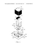
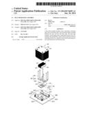
[0006] FIG. 1 is an exploded, isometric view of an exemplary embodiment of a heat dissipation assembly, together with a motherboard.
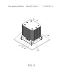
[0007] FIG. 2 is an assembled, isometric view of the heat dissipation assembly and the motherboard of FIG. 1.
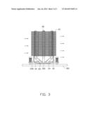
[0008] FIG. 3 is a side plan view of FIG. 2, showing the heat dissipation assembly in use.
DETAILED DESCRIPTION
[0009] The present disclosure, including the accompanying drawings, is illustrated by way of examples and not by way of limitation. It should be noted that references to "an" or "one" embodiment in this disclosure are not necessarily to the same embodiment, and such references mean at least one.
[0010] FIG. 1 shows an embodiment of a heat dissipation assembly for dissipating heat of an electronic component 302 mounted on a motherboard 300. The heat dissipation assembly includes a base 20, a first heat sink 40, a second heat sink 60, and three U-shaped heat pipes 80. In the embodiment, the electronic component 302 is a central processing unit.
[0011] The base 20 includes a bracket 22 and a connecting member 24.
[0012] The bracket 22 includes a substantially rectangular bottom wall 222. The bottom wall 222 defines a rectangular opening 223 in a middle of the bottom wall 222, and a plurality of screw holes 224 located at two opposite sides of the opening 223. Two opposite and spaced baffling pieces 226 extend up from each side of the bottom plate 222, and cooperatively bound a cutout 227. Four fasteners 228 are respectively installed on four corners of the bottom wall 222, to be mounted to the motherboard 300. The electronic component 302 is received in the opening 223 of the bracket 22.
[0013] The connecting member 24 includes a rectangular supporting plate 242 and two flanges 244 extending out from upper portions of two opposite ends of the supporting plate 242. Each flange 244 defines a plurality of through holes 246. A top of the supporting plate 242 defines three receiving slots 247 parallel to the flanges 244.
[0014] The first heat sink 40 includes a plurality of fins 42 each defining a plurality of inserting holes 44.
[0015] The second heat sink 60 includes a rectangular bottom plate 62 and a plurality of fins 64 perpendicularly extending up from the bottom plate 62. A bottom of the bottom plate 62 defines three parallel receiving slots 66, opposite to the fins 64.
[0016] Each heat pipe 80 includes a positioning portion 82, two heat-conductive portions 84, and two connecting portions 83 respectively connected between two opposite ends of the positioning portion 82 and the heat-conductive portions 84.
[0017] FIG. 2 shows that in assembly of the heat dissipation assembly, the supporting plate 242 is received in the opening 223 of the bracket 22, and a bottom surface of the supporting plate 242 is abutted against the electronic component 302. A plurality of screws extends through the through holes 246 of the connecting member 24, to be screwed into the corresponding screw holes 224. A bottom of the positioning portion 82 of each heat pipe 80 opposite to the heat-conductive portions 84 is received in the corresponding receiving slot 247 of the connecting member 24, and jointed to the supporting plate 424. Thereby, the baffling pieces 226 respectively face the connecting portions 82 of the heat pipes 80. The second heat sink 60 is mounted on the supporting plate 242. Tops of the positioning portions 82 are received in the corresponding receiving slots 66, and jointed to the second heat sink 60. The heat-conductive portions 84 are inserted into the corresponding inserting holes 44 of each fin 42. The fins 42 are jointed to the heat-conductive portions 84. The fins 42 are parallel to and spaced from one another. A bottom of the first heat sink 40 is abutted against the baffling pieces 226, and jointed to the baffling pieces 226. The second heat sink 60 is located between the cutouts 227 of the bracket 22.
[0018] Referring to FIG. 3, in use, a first part of heat generated by the electronic component 302 is transferred to the second heat sink 60 through the connecting member 24 and the positioning portions 82 of the heat pipes 80. A second part of the heat is transferred to the first heat sink 40 through the heat-conductive portions 84 of the heat pipes 80. Airflow generated by system fans (not shown) flows through the fins 42, and the fins 64 from the cutouts 227. The airflow can fully contact with the first and second fins 42 and 64, to increase heat-dissipation effectiveness.
[0019] While the disclosure describes examples and embodiments, it is to be understood that the disclosure is not limited thereto. On the contrary, the disclosure is intended to cover various modifications and similar arrangements as would be apparent to those skilled in the art. Therefore, the scope of the appended claims should be accorded the broadest interpretation so as to encompass all such modifications and similar arrangements.
User Contributions:
Comment about this patent or add new information about this topic:
Images included with this patent application:
 |  |
 |  |
| Similar patent applications: | |
| Date | Title |
|---|---|
| 2014-12-18 | Complex heat dissipation assembly |
| 2014-11-20 | Heat dissipating system |
| 2014-11-27 | Heat dissipation plate |
| 2014-10-02 | Heat dissipating pad |
| 2014-10-23 | Heat sink assembly apparatus |
| New patent applications in this class: | |
| Date | Title |
|---|---|
| 2022-05-05 | Heat pipe and heat dissipation structure |
| 2016-12-29 | Cooling electronic devices in a data center |
| 2016-12-29 | Two-phase cooling devices with low-profile charging ports |
| 2016-12-29 | Personal thermal management system |
| 2016-09-01 | Heat exchange system and method |
| New patent applications from these inventors: | |
| Date | Title |
|---|---|
| 2014-12-25 | Server with a function of generating fan table and method for generating fan table |
| 2014-11-13 | Air duct |
| 2014-07-03 | Air duct |
| 2014-04-17 | Airflow guide member |
| Top Inventors for class "Heat exchange" | |
| Rank | Inventor's name |
|---|---|
| 1 | Levi A. Campbell |
| 2 | Chun-Chi Chen |
| 3 | Tai-Her Yang |
| 4 | Robert E. Simons |
| 5 | Richard C. Chu |