Patent application title: Effluent Flow Splitter
Inventors:
Christ Spoorenberg (Ballintogher, IE)
IPC8 Class: AF16L5500FI
USPC Class:
137561 A
Class name: Fluid handling systems non-valved flow dividers
Publication date: 2014-06-12
Patent application number: 20140158231
Abstract:
The point of the invention is to improve the distribution of waste water
or effluent over a sewage treatment system based on irrigation of a
plantation. Typically the effluent may come from a septic tank overflow
and needs to be fed evenly into a number of discharge pipes that would be
located underground in a percolation area.
The device related to this invention is characterised by a container with
an inlet at the top, located underneath the septic tank overflow, and a
number of outlets at the bottom. Inside the container the effluent is
funnelled and subsequently poured onto the centre of a flow splitter
plate. To make the fluid spread radian and uniformly towards the plate's
perimeter this plate is made of a porous material and is convex shaped.
The fluid eventually flows uniformly over the plate's edge and is evenly
distributed over a number of separated outlets underneath.Claims:
1. A device for dividing a flow of fluid matter, for example effluent or
sludge, over a plurality of outlets whereby said device consists of a
container, an inlet at top and outlets at the bottom, through which the
fluid flows by gravity, via a vertical spout, on to the centre of a fluid
spreading surface, which is curved in a convex manner to make the
descending fluid spread radially and uniformly towards the surface's
outer edge into said outlets or into collection chambers, with outlet
pipes connected, underneath said edge, thereby dividing the fluid evenly
over said outlets.
2. A device according to claim 1 in which said fluid spreading surface is curved in a convex manner in its centre area and continues as a cone shaped surface, in a descending orientation.
3. A flow distribution device according to either of claims 1 and 2 in which said fluid spreading surface is provided with a rotational symmetric pattern of protruding elements, dimples, ribs or grooves, to give the spreading of the fluid increased uniformity and to secure the fluid to flow radially.
4. A flow distribution device as claimed in any preceding claim in which said fluid spreading surface, whole or partly, consists of porous material, for example ceramic, an open-cell foam or a porous fibre cloth, to increase adhesion between the surface and the spreading fluid and thereby the uniformity in the spreading of the fluid.
5. A flow distribution device as claimed in any preceding claim whereby the outer perimeter of said fluid spreading surface forms a dripping edge that is provided with a multitude of tooth-like or wave-like vertical oriented extensions to prevent the fluid to nm tangentially alongside the outer perimeter to an adjacent, and therefore not designated, outlet or collection chamber.
Description:
FIELD OF THE INVENTION
[0001] The present invention relates to waste water treatment systems based on irrigation of an area planted with trees, reed or the likes, designed for breakdown of sewage or other organic effluent. The system also relates to systems without any specific plantation that would be commonly known as a percolation area. The invention particularly relates to the distribution point where the flow of effluent, gravity fed from the overflow of a septic tank, is divided over a number of effluent pipes that are underground located in the plantation bed. Finally the invention relates to the handling and distribution of any fluid matter including examples such as salt water or sludge, whereby the use of moving parts is not desired and whereby a small inaccuracy in distribution is allowed.
BACKGROUND TO THE INVENTION
[0002] Many percolation fields contain heavily polluted areas due to poor distribution of the effluent towards the underground effluent pipes at the distribution point. Often the total overflow from the septic tank is fed into one pipe only. As a result of this, only a small area of the bed is dealing with supply of effluent, which comes in abundant proportions, and subsequently ends up being unable to break this down. In these cases, other areas that are linked to the system obviously do not receive effluent of any significance and therefore do not contribute to the system. This malfunctioning results in an overall inefficiency, pollution related complaints and problems with acceptance of these systems.
[0003] Looking closer to a common distribution box, often a simple concrete or plastic casing with a number of holes near the bottom, it is obvious to notice that some of the connected outlets are not positioned on an equal level in the box to provide an even distribution. An equal level can be achieved in theory only as these solutions deal with manufacturing and installation inaccuracies and, after some time, movement of the soil causing a distribution box to tilt to a slight angle. Furthermore the slightest sewage residue build-up will cause obstruction for effluent to enter any particular pipe thereby making an even distribution even more unlikely.
[0004] Although the problem may seem to apply predominantly for small trickling or dripping flows it certainly applies to higher flow rates too. The scattering or splashing of effluent, which may come with a high flow rate when it hits the bottom of a common distribution box, may be believed to be uniform but will have a preferred direction as determined by the position and shape of the septic overflow or a baffle plate, if present.
[0005] The principle problems as described above can be overcome by inserting the device related to this invention, an effluent flow splitter, which offers a secure solution for an even distribution of the effluent over its connected pipes even when fitted under a slight angle.
STATEMENT OF INVENTION
[0006] The device related to this invention comprises a container with an inlet at the top and a multitude of outlets at the bottom. The system is gravity fed. The device typically carries inside this container: a funnel in the upper section with a spout at its outlet, a flow splitter plate positioned directly underneath and a number of outlets at the bottom of the container.
[0007] The funnel has means to baffle the incoming flow and, provided with a narrow spout to secure a straight flow or dripping of effluent, avoids an uncontrolled scatter, to the centre of the flow splitter plate.
[0008] The flow splitter plate is designed to a particular and rotational symmetric shape to prevent the effluent flowing unevenly into one or more random directions. Its top surface is predominantly convex shaped and is provided with a rotational symmetric area of protruding shapes, particular in its centre, onto which the drops of effluent will be directed.
[0009] When drops reach the centre of the splitter plate's surface, a film or bed of effluent will be formed initially in the centre area as a result of a balance between surface tension, cohesive and adhesive forces and size and shape of the centre area. At the point of saturation of said area the surface tension along the perimeter of this area has increased to its maximum but will be uniform. At this point the film has already spread but will eventually break along this area's perimeter, resulting into drops which will descend following the convex surface that provides a radial uniform yet descending slope. The slope also forces clusters of drops to separate on their continuing descent, under mentioned gravitational force, as all drops will find their own radian path the steepest and therefore preferable. With a continues curved convex shape of the plate's surface the expanding film or bed will automatically find that break point at some stage and is therefore considered a preferable shape above a cone, let alone a flat plate. The surface however, may have areas that are conical shaped or even cylindrical.
[0010] It is highly beneficial to have the splitter plate's surface made of a material with absorbing qualities. This will provide uniform adhesive forces after having broken the fluid's surface tension and prevent a descending drop of fluid to drag effortlessly other drops along into an ongoing stream into one direction only. The adhesive forces that come with the absorbing qualities even allow a slight distribution in upward direction. In general terms the porosity will add robustness to the principle and allows the systems to work adequately even under a noticeable angle.
[0011] A number of radian positioned vertical ribs may be fitted to this plate to further prevent drops of fluid moving to adjacent partitions on their descent towards the outer perimeter of the flow splitter plate and therefore provide additional guidance towards designated outlets.
[0012] The splitter plate's outer perimeter has a dripping edge with a specific shape to prevent the descending effluent to run along the perimeter towards an adjacent outlet. Despite many embodiments thinkable, the dripping edge will preferably be shaped as a toothed vertical rim, downwards oriented.
[0013] Finally the fluid will flow into the outlets that are positioned underneath the dripping edge. For a better accuracy and particular if the outlet pipes run i.e. horizontally, there is a need to separate the outlets by vertical partitions, thus forming collection chambers or likewise, to prevent the fluid to run across the bottom surface into the wrong outlet pipe.
[0014] The distribution of effluent over the outlets is within an acceptable accuracy and without use of moving parts or power supply. Particular the lack of moving parts is a necessity as sewage treatment systems are generally not easy accessible for maintenance and repairs. They are also highly subject to an un-clean and harmful environment whereby the use of moving parts would imply the need for regular maintenance, excessive costs and high risks of breakdown.
[0015] Ultimately the device secures an evenly distributed flow towards each effluent pipe over a large working range and therefore forms a foundation for a proper functioning percolation area subsequently waste treatment.
BRIEF DESCRIPTION OF THE DRAWINGS
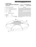
[0016] FIG. 1: 3-dimensional front view with funnel, flow splitter plate, cross sections of container, inlet plate, support plate and guide ring.
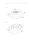
[0017] FIG. 2: 2 dimensional cross section front view
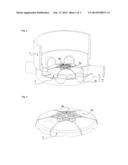
[0018] FIG. 3: 3-dimensional front view with flow splitter plate and cross section of container.
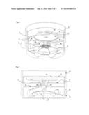
[0019] FIG. 4: 3-dimensional view of flow splitter plate
[0020] FIG. 5: 3-dimensional view of flow splitter plate, alternative
[0021] FIG. 6: 3-dimensional view of flow splitter plate , alternative
DETAILED DESCRIPTION
[0022] The device consists of a vertically oriented container (1) that generally will be cylindrically shaped. Inside are located: an inlet plate (2), a funnel (3) which is positioned in a support plate (4), a guide ring (5) and a flow splitter plate (6).
[0023] The container is open at the top and may have an edge (1a) around its outer perimeter that is extended upwards with the function to catch and collect uncontrolled flows of effluent, coming from a septic tank overflow for example, thus preventing effluent to be spilled over the device. The container has in its bottom section a multitude of upstanding ribs (1b) incorporated to divide the bottom's surface into a number of separated chambers. Each chamber has its outlet (1c) through the bottom plate or through the wall of the bottom section, which is provided with means for connectivity with its designated effluent pipe. The upstanding ribs are obsolete if the outlets are in the bottom plate and their function is incorporated in the shape of these outlets.
[0024] The inlet plate provides inlet to the system via one or more holes (2a) that are located above the funnel inside. None of said holes is aligned vertically with the funnel's outlet underneath, thereby providing also a baffling function. The holes have a small dripping edge at the bottom along their perimeter.
[0025] The funnel has basically the shape of a bowl or saucer with a hole in its centre underneath which the spout (3a) is placed. As the spout has to be narrow at its end, i.e. forming a tip, to keep the flow concentrated towards the centre of the system, it is constructed in a way that the effluent can run over its surface instead of through a narrow gap in the centre, to prevent clogging up. This is done by placing large holes (3b) at the base of the spout through which the effluent will flow from the inside towards the outside of the spout. From there it will continue flowing downwards over the spout's surface towards the tip at its end.
[0026] The support plate carries the funnel and secures its centred position. It has also a number of holes (4a) that function as a bypass for the funnel in case of inundation during which the funnel will over flow. In this case the excessive fluid will pass through these holes and eventually be directed to the centre of the device, again via a hole (5a) in the centre of the guide ring and eventually in the centre area of the flow splitter plate underneath. Mentioned holes have a small dripping edge along their perimeter.
[0027] The flow splitter plate's basic shape is circular. Its top surface is convex or conical shaped (6a) or a combination there of, in a descending orientation.
[0028] Particularly the centre area of the splitter plate may contain a number of protruded shapes (6b) such as ribs, domes, dimples or grooves. An alternative embodiment of the plate has an additional vertical descending step (6c) towards the remaining surface area. The splitter plate may be made of any material but a material with absorbing properties is preferable, particularly for said centre area. Another alternative embodiment has a multitude of perpendicular ribs (6d) that are be radial positioned, starting in the area with the protruding elements and eventually extending over a length that reaches slightly beyond the outer perimeter of the plate. The outer perimeter of the flow splitter plate is extended downwards and contains a multitude of notches (6e) at least equal to the number of outlets. The number of notches can be extended and ultimately create a strong resemblance with a row of shark teeth or a comb.
User Contributions:
Comment about this patent or add new information about this topic:
Images included with this patent application:
 |  |
 |  |
| Similar patent applications: | |
| Date | Title |
|---|---|
| 2009-07-16 | Tee flow splitter |
| 2014-02-06 | Manifold flow splitter |
| 2010-08-12 | Flow splitter |
| 2011-10-27 | Electronic flow sensor |
| 2014-06-05 | Electronic flow sensor |
| New patent applications in this class: | |
| Date | Title |
|---|---|
| 2016-06-23 | Net shaped forging for fluid ends and other work pieces |
| 2016-06-16 | Quick-connect system for a high pressure connection |
| 2016-03-31 | Refrigerant distributor and refrigeration cycle device equipped with the refrigerant distributor |
| 2016-03-10 | Inject insert for epi chamber |
| 2016-01-07 | Apparatuses for distributing fluids in fluidized bed reactors |
| Top Inventors for class "Fluid handling" | |
| Rank | Inventor's name |
|---|---|
| 1 | Nobukazu Ikeda |
| 2 | Kouji Nishino |
| 3 | Ryousuke Dohi |
| 4 | Kevin T. Peel |
| 5 | Huasong Zhou |