Patent application title: System for Knee Extension Therapy
Inventors:
Robert E. Tennant (Portland, OR, US)
IPC8 Class: AA63B2304FI
USPC Class:
482139
Class name: Exercise devices user manipulated force resisting apparatus, component thereof, or accessory therefor user interface element
Publication date: 2014-06-05
Patent application number: 20140155235
Abstract:
The present invention concerns a system that is useful to apply
controlled, gradual muscular stretching, and is particularly useful for
knee extension therapy.Claims:
1. An system for knee extension therapy, comprising: an elongated base; a
thigh strap configured for strapping a patient's thigh to the base a boot
member; an expandable member connected to the boot member and supported
by the base away from the thigh strap and configured so that expansion of
the expandable member causes movement of the boot member away from the
base, thereby forcing extension of the knee.
2. The system of claim 1 wherein the expandable member is an inflatable bladder.
3. The system of claim 1 wherein system is configured so that expansion of the expandable member causes rotation of the boot member as the boot member moves away from the base and so that the thigh strap prevents the patient's thigh from moving away from the base.
4. The system of claim 3 wherein the expandable member is a bladder that is connected along a length of the boot member and is configured to expand between the boot member and the base by a varying amount along the length of the boot member.
5. The system of claim 1 wherein the boot member includes a strap for securing the user's foot within the boot member.
6. The system of claim 1 including a remote control for controlling expansion of the expandable member.
7. The system of claim 6 including a control for permitting contraction of the expandable member.
8. The system of claim 6 wherein the expandable member is an inflatable bladder and the remote control includes a pump for inflating the bladder.
9. The system of claim 8 wherein the remote control also includes valving that is operable for deflating the bladder.
10. The system of claim 7 wherein the remote control is manually operated by the user.
11. The system of claim 1 wherein the base is hinged for reducing its length for storage.
12. A method for knee extension therapy for a patient comprising the steps of: securing to an elongated base a patient's thigh; placing the patient's foot in a boot member on the base; and gradually moving the boot member away from the base to thereby produce forces in the leg for extending the knee.
13. The method of claim 12 further comprising the step of gradually expanding an expandable member between the boot member and the base.
14. The method of claim 13 wherein the expanding step includes inflating an inflatable bladder; and linking together the boot member with a plate, thereby to guide movement of the boot member.
15. The method of claim 13 wherein the expanding step comprises the step of manually pumping fluid into a bladder to inflate the bladder; and manually controlling the occasional deflation of the bladder to allow the boot member to return toward the base, thereby to reduce the forces in the leg.
Description:
TECHNICAL FIELD
[0001] This application relates to a system for stretching a person's muscles, such as the hamstring muscles as well as the muscles and other tissues comprising the articular capsule of the knee joint.
BACKGROUND
[0002] The terms "hamstring," "hamstrings" or "hamstring muscle" are generally used to refer to the three large muscles constituting the back of the upper leg. The hamstrings serve to flex the knee joint and extend the hip. Everyday activities as well as most athletic activities involve the repetitive contraction of the hamstring muscle. The hamstring muscle tightens as a result, and requires effective stretching to retain its full range of motion. In the absence of such stretching, the tight hamstrings will have a deleterious effect on the person's skeletal alignment, typically resulting in lower back and knee pain, as well as problems with posture.
[0003] Full extension of the knee is often lost as a result of knee injury and related surgery. Careful and sustained physical therapy is required for a patient after surgery in order to regain full knee extension. A patient can be instructed by a physical therapist as to the proper way to stretch the leg to recover knee extension, and a patient is often left responsible to carry out the therapy on their own at frequent intervals between visits with the physical therapist.
[0004] Stretching any muscle is best done at a slow rate. Attempting to quickly stretch the muscle will rouse the muscle's inherent tendency to contract when pulled, thereby resisting the sought-after lengthening of the muscle.
[0005] Also, knee extension therapy is often most successful when the stretching applied to the muscles is done in increments separated in time by relaxation of the muscles. This may be referred to as a contraction/relaxation therapy technique.
SUMMARY OF THE INVENTION
[0006] The present invention concerns a system for knee extension therapy that is useful for controlled, gradual muscular stretching, and is particularly useful for controlled stretching of the hamstring muscle, ligaments, and tendons of the knee, including the entire the articular capsule of the knee joint.
[0007] In a preferred embodiment, the system for knee extension therapy includes an elongated base and a thigh strap configured to strap a patient's thigh to the base. A boot member is supported on the base to receive the patient's foot. An expandable member is connected to the boot member and supported by the base away from the thigh strap. The expandable member is configured so that expansion of the expandable member causes movement of the boot member away from the base, thereby forcing extension of the knee.
[0008] In another embodiment, the system can be modified for primarily stretching the hamstring muscles. In this embodiment, the stretched leg extends generally vertically upwardly adjacent to a stationary vertical surface. The stretched leg is supported for controlled, slow, forced rotation about the hip, away from that surface, thereby to stretch the hamstring muscle.
[0009] Preferably, the user of the system is situated so that, apart from the stretched leg, the remainder of the person's muscle groups are relaxed, thereby allowing a focused effort for stretching the hamstring muscle.
[0010] Other advantages and features of the present invention will become clear upon study of the following portion of this specification and drawings.
BRIEF DESCRIPTION OF DRAWINGS
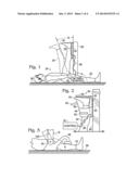
[0011] FIG. 1 is a diagram illustrating in a side view one embodiment of a system made in accordance with the present invention.
[0012] FIG. 2 is an enlarged view of an expandable part of the system of FIG. 1.
[0013] FIG. 3 is a diagram illustrating in side view a portion of an alternative embodiment of the present invention.
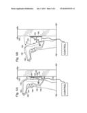
[0014] FIGS. 4A and 4B are side views showing another embodiment of the present invention.
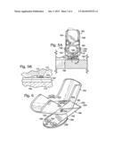
[0015] FIG. 5A is a bottom view of the embodiment of FIGS. 4A and 4B.
[0016] FIG. 5B is an enlarged detail view taken from FIG. 5A.
[0017] FIG. 6 is a perspective view showing a portion of another alternative embodiment.
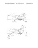
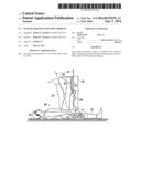
[0018] FIGS. 7A and 7B are side views showing another embodiment of the invention, comprising a system for knee extension therapy.
DESCRIPTION OF PREFERRED EMBODIMENTS
[0019] The first portion of this description relates to an embodiment comprising a system made in accordance with the present invention that is amenable for use in yoga exercises or physical therapy, with or without additional components for supporting or isolating the hamstring muscles to be stretched. This embodiment and alternatives are described in the following text associated with FIGS. 1-6. That discussion is followed by another embodiment of the invention that supplements the foregoing with the text associated with FIGS. 7A and 7B, which illustrate the system for knee extension therapy.
[0020] FIG. 1 illustrates a stretching system that is employed by a user 20 for controlled, gradual stretching of the hamstring muscle. The system may be operated while the user 20 is reclined, on his back, with one "rested" leg 22 extending horizontally on a flat surface 28. The other "stretched" leg 24 is rotated at the hip and extends vertically upwardly, with the knee held straight. The back of the stretched leg 24 is adjacent to the surface of a stationary, rigid member 26.
[0021] In one embodiment, the member 26 may be an existing doorjamb, which is the vertical component of a door frame. In such an embodiment, the components of the stretching system include an expandable member 30 that will hereafter also be referred to as an expander 30. The expander 30 is located adjacent to the vertical member 26 between that member and the back of the user's stretched leg 24. The expander 30 may abut or be removably attached to the stationary surface of the vertical member.
[0022] The expander 30 is cushioned and/or contoured to comfortably receive the stretched leg, preferably in the vicinity of the user's Achilles tendon. In this regard, the expander 30 may have a boot-like configuration as shown in FIG. 2 and discussed more below.
[0023] The expander 30 is controlled for providing incremental or gradual expansion from a contracted position to an expanded position for correspondingly gradual stretching of the user's hamstring muscle. As one aspect of this invention, the user may maintain the reclined position while remotely controlling the expander 30.
[0024] In the contracted position of the expander 30, the user's stretched leg 24 is generally vertical, thus making an angle "A" of about 90 degrees with the horizontal surface 28. The contracted position of the expander 30 appears in FIG. 1 as cross-hatching of the back portion of the expander 30 that is between the leg 24 and the vertical member 26. Movement of the expander 30 toward the expanded position (shown in dashed lines in FIG. 1) increases the angle between the stretched leg 24 and the surface 28 by angle "B" from vertical. The act of gradually moving the user's leg 24 through the angle "B" effectively stretches the hamstring muscle of that leg.
[0025] As noted, the expansion of the expander 30 is controlled by the user in a manner that permits the user to maintain an otherwise relaxed, reclined position. To this end, a remote control 32 is positionable near the hand 34 of the user. The expansion of the expander 30 may be provided by a pneumatic system, and the control 32 may comprise a hand pump or other valving that communicates with the expander 30 via line 36 for directing pressurized air into the expander 30 to expand it. The control 32 may also include a release valve for slowly returning the expander to the contracted state upon completion of the desired stretching time. A conventional sphygmomanometer bulb will suffice as the pump and release valve.
[0026] It is also contemplated that the control can be electronically automated with a simple controller for activating an air pump and associated valves for inflating and deflating the expander 30 in accord with built-in or user-defined programming.
[0027] FIG. 2 illustrates in greater detail a preferred embodiment of the expander 30. In this embodiment, the expander 30 has a boot-like configuration that includes a bottom 42, a back 44, and two opposing sidewalls 46, 48. The expander 30 may be formed of, for example, sewn synthetic material, such as nylon, that forms the outer casing for internal cushioning and an expandable air bladder 50. The bottom 42 of the expander 30 extends across the sole of the user's foot 25. The back 44 of the expander 30 extends from the rearward end of the bottom and along the back of the user's leg 24 generally adjacent to the Achilles tendon.
[0028] The sidewalls 46, 48 are attached to or integrally formed with the bottom 42 and back 44 and extend therefrom in a generally parallel relationship across the sides of the user's foot 25, ankle, and lower leg. Between the sidewalls 46, 48 at the forward edge of the expander 30 (that is, the leftmost side in FIG. 2) there is an open space to permit the user to insert the foot 25 into the expander. Preferably, the sidewalls 46, 48 carry one or more straps 52 with associated hook and loop fastening to secure the sidewalls together with the foot inserted into the expander 30.
[0029] The bottom 42 and sidewalls 46, 48 may be filled with cushioning (shown cross-hatched in FIG. 2), such as foam, to provide a snug, comfortable fit when the expander is worn. The back 44 houses the expandable air bladder 50 to which the pneumatic line 36 is coupled. As described above, the system is controlled by the user to direct pressurized air through the line 36 for controlled expansion of the bladder 50 and consequent stretching of the hamstring muscle.
[0030] In a preferred embodiment, the bladder 50 and back 44 are configured so that the portion of the back 44 that is placed in contact with the vertical member 26 remains relatively flat or planar, and the expansion of the bladder 50 is thus primarily directed toward the user's leg 24. Moreover, the bladder 50 is shaped so that in expanding away from the stationary surface the bladder enlarges by a progressively greater amount in the direction toward its outermost (upper) part (note the broken line 30 in FIG. 1), so that the portion of the leg that contacts the back 44 of the expander 30 is supported in a generally straight line.
[0031] FIG. 3 shows an alternative embodiment of the invention whereby the vertical member 126 is integrated with the system. In one approach, the vertical member 126 is in a stationary vertical position and carries the expander 30 (FIGS. 1 and 2). Branching from the vertical member is a brace 38 that is configured to provide contact with the knee of user's rested leg 22, so that leg 22 does not bend upwardly (as it otherwise tends to do) while the other leg 24 is being stretched.
[0032] As another approach to the integrated vertical member embodiment (FIG. 3), the vertical member 126 is constructed to rotate about a pivot point 40 to provide the user-controlled increase in angle "B" mentioned above. Any suitable pneumatic, hydraulic or mechanical system would be employed for moving the member 126. This type of movable member could be used without, or in combination with, an expander 30.
[0033] FIGS. 4A and 4B illustrate another preferred embodiment of the present invention. These figures show a side view of this embodiment, which includes a rigid, thin back plate 144. The back plate 144 comprises two layers: a rigid plastic layer 146, such as acrylonitrile butadiene styrene (ABS) to which is bonded an outer layer 148, such as polyester felt. The outer layer 148 bears against a stationary surface 150, such as the surface of a doorjamb, and permits slight vertical sliding movement of the system along the doorjamb without marring that surface.
[0034] It is noteworthy here that the back plate 144 may be constructed in a variety of other configurations. For example, the back plate could be mounted to a vertical pole or other structure in a fitness club and adjustable in height to enable use of the system by users of various heights (that is, leg lengths). It will be appreciated that the presently described embodiment, featuring abutting contact with a doorjamb, for example, provides a readily portable and compact system that may be used in various locations around the user's house, hotel room, etc.
[0035] A generally U-shaped linkage 152 (see especially, FIG. 5A) is pivotally mounted to the back plate 144. That linkage includes a pair of arms 154, one arm extending from each of the opposing ends of a connector part 156 of the linkage that extends across the inner surface 158 of the back plate 144. The connector part 156 is secured by spaced-apart sleeves 157 that are fastened to the back plate 144 to make a hinge-like, pivoting connection of the linkage 152 so that the arms 154 are able to swing about the long axis of the connector part 156 toward and away from the back plate 144.
[0036] The free end of each arm 154 of the linkage is pivotally attached as at 159 to opposite sides of a boot member 160. The linkage arms 154 are rigid, preferably metal, and serve to stabilize the position of the boot member 160 relative to the back plate 144. The linkage 152 also controls or guides the movement of the boot member as it moves away from and toward the plate.
[0037] The boot member 160 may be a molded plastic member, or cut from a flat sheet of plastic (such as polyethylene) and bent and joined to define a bottom 162 and sidewalls 164, 166 into which fits the foot 125 of a user.
[0038] One of the sidewalls 164, 166 carries a strap 168 with associated hook and loop fastening. The free end of the strap is threaded through an aperture in the other sidewall so that the strap may be folded back on itself to secure the sidewalls together and hold the user's foot within the boot member 160.
[0039] The boot member 160 may be formed solely of somewhat rigid plastic or, preferably, lined with foam cushioning to enhance the comfort of the boot member.
[0040] An expandable bladder 170 is connected to the boot member 160 and to the inner surface 158 of the back plate 144. The bladder 170 is formed or two air-impermeable plastic sheets that are heat-welded together at their peripheral edges. Preferably, the heat-welded edge of the bladder is made wide enough to define a flange 173 (FIG. 5B) to which are riveted the male portions 172 of conventional snap fasteners. The male portions 172 on the bladder flange engage corresponding female portions 174 of snap fasteners that are carried on the both the back 176 of the boot member 160 and on the inner surface 158 of the back plate. In this embodiment, two spaced-apart snap fasteners are thus provided for attaching part of the bladder flange 173 to the boot member, and two fasteners are so used to attach another part of the bladder flange to the back plate 144. It will be appreciated that there may be a variety of alternative ways to attach the bladder between the boot member and back plate. For example, the bladder flange may be stapled or bonded to those respective components.
[0041] A pneumatic line 178 couples to the bladder for conducting air to and from the bladder as discussed above in connection with the earlier-described embodiment.
[0042] It is noteworthy that the bladder 170 is somewhat trapezoidal in shape (See FIG. 4B) when fully inflated. In this regard, the bladder 170 is connected along a length of the back 176 of boot member, generally adjacent to the user's Achilles tendon, and configured to expand between the boot member 160 and the stationary surface 150 by a varying amount along the length of the boot member in the direction toward the heel 180 of the user. This configuration of the bladder, in conjunction with the pivotal connection with the linkage 152, causes rotation of the boot member as the boot member moves away from the stationary surface so that the stretched leg can be held straight as it rotates about the hip.
[0043] FIG. 6 is an isometric view showing a portion of another alternative embodiment that employs a linkage 182 that is essentially a modification of the linkage 152 described above. The bladder and other components have been omitted for illustration purposes. The modified linkage provides the same stability and guidance as mentioned above, but also provides a relatively greater travel distance for the boot member 184 away from the back plate 186, thereby to provide a greater amount of muscular stretching.
[0044] The linkage of FIG. 6 includes two pivotally attached parts: a plate-mounted part 188, and a boot-mounted part 190. The plate-mounted part 188 is generally U-shaped and includes a pair of arms 192, one arm extending from each of the opposing ends of a connector part 194 of the linkage that extends across the inner surface 258 of the back plate 186. The connector part 194 is secured to the surface 258 by spaced-apart sleeves 196 that are fastened to the back plate 186 to make a hinge-like, pivoting connection of the plate-mounted linkage part 188 so that the arms 192 are free to swing about the long axis of the connector part 194 toward and away from the back plate 186.
[0045] The free end of each arm 192 is pivotally joined to the U-shaped, boot-mounted part 190 of the linkage at the location 204 where the connector part 200 of that linkage joins the arms 202. The free ends of those boot-mounted linkage arms 202 are each pivotally attached as at 206 to opposite sides of the boot member 184. As mentioned, this two-bar linkage 188, although able to collapse so that the boot member 184 can move adjacent to the back plate 186, also permits a relatively large travel distance for the boot member away from the back plate.
[0046] Turning now to the embodiment preferred for knee extension therapy, reference is made primarily to FIGS. 7A and 7B. This system includes a boot member 360 that, unless discussed otherwise below, is constructed like boot member 160 or 184 of the prior embodiments and includes a bottom 362, and sidewalls 366 between which fits the foot 325 of a user, such as a patient undergoing post-operative knee extension therapy.
[0047] The boot member 360 carries a strap 368 with associated hook and loop fastening. The free end of the strap is threaded through an aperture in the other sidewall so that the strap may be folded back on itself to secure the sidewalls together and hold the user's foot within the boot member 360.
[0048] A back plate 344, like the back plate 144 discussed above, comprises a rigid plastic layer to which is bonded an outer layer, such as polyester felt. The outer layer bears against a thin, rigid base 350. The base may be, for example, rigid plastic or wood.
[0049] A generally U-shaped linkage (like 152 in FIG. 5A) is pivotally mounted to the back plate 344. That linkage includes a pair of arms; with one arm 354 extending from each of the opposing ends of a connector part of the linkage that extends across the inner surface (that is facing away from the base 350) of the back plate 344. The connector part makes a hinge-like, pivoting connection of the linkage to the back plate 344 so that the arms 354 are able to swing toward and away from the back plate 344.
[0050] The free end of each arm 354 of the linkage is pivotally attached as at 359 to opposite sides of the boot member 360. The linkage arms 354 are rigid, preferably metal, and serve to stabilize the position of the boot member 360 relative to the back plate 344. The linkage also controls or guides the movement of the boot member as it moves away from and toward the back plate.
[0051] An expandable bladder 370 is connected to the boot member 360 and to the inner surface of the back plate 344. The bladder 370 is preferably formed and attached as discussed above with respect to bladder 170
[0052] A pneumatic line 378 couples to the bladder for conducting air to and from the bladder under the control of the user as discussed above in connection with the earlier-described embodiment. In this embodiment the control for inflating and deflating the bladder is preferably a conventional sphygmomanometer bulb 332 (FIG. 7B), that can be squeezed by the patient for inflating the expandable bladder. The bulb 332 includes a normally-closed deflation valve 333 that, upon manipulation by the user, can be opened for venting the bladder 370 to atmosphere and thus allowing the bladder to collapse.
[0053] This embodiment the system also includes a thigh strap 340 that is employed for securing the patient's leg 324 to the rigid base 350 at the patient's thigh so that the patient's knee is between the thigh strap 340 and boot member 360. The strap 340 may be an suitable material for comfortably securing the leg 324 in place, with sufficient tensile strength for resisting movement of the patient's thigh away from the base 350 as the bladder 370 (FIG. 7A) is fully inflated (FIG. 7B). A single woven nylon strap with cooperating hook and loop fastening may be employed.
[0054] With reference to FIG. 7A, the leg 324 of a patient seeking knee extension therapy is located adjacent to the base 350, with the foot 325 strapped into the boot member 360. The patient's thigh is then snugly strapped 340 to the base. In this position, the patient's knee is not fully flexed, as illustrated by the knee-extension angle "E" of FIG. 7A, which is substantially less than 180 degrees.
[0055] The patient then repeatedly squeezes the bulb 332 for gradually inflating the bladder 370, thereby lifting the boot member 360 (hence the foot 325) above the base 350, while the thigh strap prevents the leg above the knee from lifting from the base. As a result, the hamstring muscle stretches and the tissues surrounding the knee react such that the knee extends to increase the knee-extension angle "E" toward 180 degrees or beyond.
[0056] It will be appreciated that the patient-operated bulb 332 enables the patient to personally control the rate of forced knee extension and attendant pain level. Moreover, the hand manipulated deflation valve 333, allows the patient to occasionally deflate the bladder for temporarily relaxing the amount of stretch. As a result, the knee extension is done in increments separated in time by relaxation of the muscles to accomplish the contraction/relaxation therapy technique mentioned above.
[0057] It will also be appreciated that the patient may partially extends the knee joint by partly inflating the bladder 370 so that (while the deflation valve 333 is closed) the leg is held in a desirable position for effective isometric training of the affected joint muscles.
[0058] While the present invention has been described in terms of preferred embodiments, it will be appreciated by one of ordinary skill in the art that modifications may be made without departing from the teachings and spirit of the invention. For example, it is contemplated that the back plate 344 be readily removed from the base, and the base 350 may be hinged in one or more locations to enable the base to be made more compact for storage or transportation when not in use. Also, the function of the thigh strap could be accomplished with any of a variety of mechanisms, such as hoops or brackets, for keeping the thigh against the base. The general notion of "strapping" the thigh to the base thus includes such mechanisms.
[0059] Moreover, the air bladder could be replaced with a foam- and/or compression-spring-filled interior that is compressed before use and controlled so that the natural resilience of the foam and/or spring expands the bladder and displaces the boot member from the back plate. A fluid-driven, lightweight telescoping member might also be used alone or with a bladder to expand the distance between the boot member and the back plate.
User Contributions:
Comment about this patent or add new information about this topic:
Images included with this patent application:
 |  |
 |  |
 |
| New patent applications in this class: | |
| Date | Title |
|---|---|
| 2022-05-05 | Ergonomic exercise equipment handle |
| 2016-09-01 | Weight bar assembly |
| 2016-07-14 | Exercise machine with a detachable stabilizing support assembly having adjustable positions |
| 2016-06-09 | Elastomeric hand grips |
| 2016-04-21 | Lever with slider |
| Top Inventors for class "Exercise devices" | |
| Rank | Inventor's name |
|---|---|
| 1 | William T. Dalebout |
| 2 | Scott R. Watterson |
| 3 | Raymond Giannelli |
| 4 | Leao Wang |
| 5 | Bruce Hockridge |