Patent application title: Release Movement Neuromuscular Developer
Inventors:
Larry Traub (Georgetown, IN, US)
IPC8 Class: AA63B21072FI
USPC Class:
482104
Class name: Utilizing weight resistance including stationary support for weight barbell support
Publication date: 2014-06-05
Patent application number: 20140155230
Abstract:
A weightlifting apparatus supports a weight bar and controls its path.
The apparatus allows a lifter to complete the full range of a lift
repetition encompassing lowering the weight and rebounding with an
explosive lift to include release of the weight bar at the end of the
lift. The apparatus controls and catches the weight bar at the bars
greatest height. A gage on the apparatus allows measurement of the height
of the bar so that progress can be measured. A spotter operates a return
and reset mechanism in the apparatus to return the bar to the control of
the lifter and to reset the catch mechanism of the apparatus.Claims:
1. A weight training apparatus comprising: a weight bar for receiving
weights; a first frame holding said weight bar; a second frame connected
to said first frame and controlling the motion of said first frame and
said weight bar; a third frame supporting said second frame; a catch
mechanism, said catch mechanism allowing a lifter to lower and then lift
said weight bar and catching said first frame and holding it at the
highest point in the lift of said weight bar during use; a return and
reset mechanism operable to return said weight bar to the initial
position; and a release mechanism operable to disengage said catch
mechanism; said return and reset mechanism operable to reset said catch
mechanism to allow subsequent lifts.
2. The weight training apparatus of claim 1, wherein: the position of said weight bar on said first frame is adjustable.
3. The weight training apparatus of claim 1, further comprising: a gauge to indicate the extent of a lift.
4. The weight training apparatus of claim 1, wherein: said third frame comprises a base and posts; said second frame comprises a parallel rocker arm mechanism pivotally mounted to said posts; and said first frame is pivotally connected to said second frame, the motion of said first frame being defined by the rocker motion of said second frame.
5. The weight training apparatus of claim 4, wherein: said catch mechanism operates between said second frame and said third frame to hold said second frame and said first frame.
6. The weight training apparatus of claim 5, wherein: said catch mechanism comprises a catch track mounted on said third frame, said catch track comprising a smooth plate aligned with a rack with teeth; and a catch tongue mounted on said second frame, said catch tongue biased to press into said catch track, said catch tongue riding on said smooth plate while said weight bar is lowered and returned, said catch tongue engaging said rack at the height of the lift.
7. The weight training apparatus of claim 6, wherein: said release mechanism withdraws said catch tongue from said rack to release said catch mechanism.
8. The weight training apparatus of claim 1, wherein: said third frame comprises a base and posts; said second frame comprises essentially vertical slides supported by said posts; and said first frame comprises a weight sled riding on said slides.
9. The weight training apparatus of claim 8, wherein: said catch mechanism operates between said first frame and said third frame to hold said first frame.
10. The weight training apparatus of claim 9, wherein: said catch mechanism comprises a chain loop carried on sprockets around said third frame, said chain loop located in a vertical plane and attached at one location to said first frame; a first catch element attached to said chain loop at another location; a second catch element attached to said third frame; said first catch element and said second catch element being in alignment and engaging with each other to hold said first frame by said chain loop.
11. The weight training apparatus of claim 10, wherein: said first catch element comprises a catch track attached to said chain loop, said catch track comprising a smooth plate aligned with a rack with teeth; and said second catch element comprises a catch tongue mounted on said third frame, said catch tongue biased to press into said catch track, said catch tongue riding on said smooth plate while said weight bar is lowered and returned, said catch tongue engaging said rack at the height of the lift to hold said first frame by said chain loop.
12. The weight training apparatus of claim 11, wherein: said release mechanism withdraws said catch tongue from said rack to release said catch mechanism.
13. The weight training apparatus of claim 1, wherein: said return and reset mechanism is powered.
Description:
CROSS REFERENCE TO RELATED APPLICATIONS
[0001] This application claims priority to U.S. Provisional Application 61/733,461 filed on Dec. 5, 2012. The entirety of U.S. Provisional Application 61/733,461 including both the figures and specification are incorporated herein by reference.
FIELD OF THE INVENTION
[0002] This invention relates to an exercise machine. More particularly, this invention relates to an exercise machine that enables an explosive lift with substantial weight, including an explosive lift ending with release of the weight.
BACKGROUND
[0003] There are many types of training used to improve physical performance, particularly for athletic performance. Among the several types of training techniques used are weight training and plyometrics. Although many types of training can be combined easily, it is more difficult to safely combine these two types of training
[0004] Weight training is used extensively and may itself be broken down into sub categories, such as free weight lifting, and machine, or apparatus, lifting. Typically, a person engaging in weight training will attempt to lift a given weight a prescribed number of times. These prescribed number of times are generally described as repetitions and they are grouped together to form a set. Depending on the goals and philosophy of the person prescribing the training regime, the number of repetitions, sets, and weights for each set may vary. For example, a person may lift a given weight for 3 sets of 8. If they can accomplish 3 sets of 8 then they may increase the weight for their next training session. As another example, a person may lift a lower weight for a larger set of repetitions and then follow that set with a larger weight and fewer repetitions in downward pyramid fashion.
[0005] Philosophy and goals may also determine whether a person trains on free weights or uses weights lifted with mechanical assistance or machines. Free weights are frequently preferred because it is believed that the stabilizing efforts that a trainer must employ to perform a lift provide additional useful strength. Weightlifting machines are frequently used when the trainer is not quite as interested in performance and so the safety provided by the weightlifting machine is given higher priority than when performance is valued higher. The weightlifting machine prescribes the motion and the extremes at both end of the lift and thereby provides assistance in the lift and the control of the weight.
[0006] Plyometrics are utilized frequently for athletic training when quick reaction and explosive power are desired. Plyometric training uses quick explosive exercises to train the muscles to react and it is believed to improve the number of muscle fibers recruited by the nerves operating the muscles. In plyometrics, it is believed that the most important and productive part of the training occurs at the rebound point of the lift, exercise, or motion. For example, a person might jump on and off of boxes of different heights. Because of the different heights of the boxes, the trainer would have to recoil to different depths to execute the jump. The different depths provide explosive training at those positions, or depths. However, if the person were to jump from a static position, such as setting on a chair and then jumping, it would not produce as beneficial a result as lowering the body and then jumping out of the lower position. It is the rebound at the lower position where significant improvements and benefits are gained. If a weight is added to the exercise, in order for the plyometric exercise to be effective, there must be a mechanically unrestricted descent of the weight to allow for the maximum rebound effect.
[0007] Because of the explosive nature of plyometrics, it is very difficult, and potentially dangerous to combine weight training with plyometrics. The explosive lifts or motions of plyometrics results in transferring substantial energy and momentum to a weight. This momentum and energy can be quite dangerous if returned directly to the lifter. This problem still exists with typical weight lifting machines, in that there is not adequate restraints on the return of the weight, even though the weight is proscribed in its path.
[0008] Another issue central to athletic training is the systematic measuring and tracking of progress. In the context of weight training, tracking the successful completion of the prescribed repetitions and sets at a given weight allows a trainer or athlete to know when to increase the weight. In the context of plyometrics, improvement may be measured by the height or distance of leaps or other metrics.
RELEVANT ART
[0009] U.S. Pat. No. 7,104,936 by Karlstrom is for a "Strength and power training system." A weight machine is used for acceleration movement of heavy weights, and jumping and throwing exercises. The weight machine includes a hydraulic cylinder that will retard movement of the weight under gravity, and will permit free movement against the force of gravity. While the weight machine of Karlstrom restrains the return of the weighted bar, it does not allow a natural rebound motion which is considered a crucial feature of plyometric training. Nor does Karlstrom provide a method of measuring the distance the weight obtains when released.
[0010] U.S. Pat. No. 6,623,409 by Abelbeck is for an "Automatic locking exercise device and method." This is an automatic locking exercise device that incorporates a one-way locking mechanism. The device includes a frame, which supports a track, preferably a pair of linear bearing rods, one on each side. A guide member, or linear bearing runs on each bearing rod and is attached to a handle, or bar, that is grasped by a user. A one-way lock is used to provide movement of the bar along the track in an upward direction but opposes movement down. In the preferred embodiment, rotating the bar actuates a lock release. This disengages the one-way lock and enables the bar to move freely up and down along the track. If the user ever drops the weight the one-way lock automatically engages and catches the weight. Explosive power training can also be performed on the device in that the user can safely throw the weight, knowing that the weight will be automatically caught at its highest point without risk of injuring someone. Marking the highest point allows the user to quantify their explosive training performance and progress. The apparatus of Abelbeck '409 provides a mechanism for catching a weight if released, but no provision is made for safely lowering the weight from its high point. The energy of the weight is still stored and ready to return to a trainer when released.
[0011] U.S. Pat. No. 7,455,629 by Abelbeck is for an "Exercise device with a safety lock." A safety locking system is used on an exercise device. The locking system includes a first pawl that is mounted to a pawl shaft. The pawl shaft is movably mounted to a lock frame, which can also support a weight collar, adapted to receive weight plates to provide additional resistance to exercise. A second pawl is movably mounted to the lock frame and is connected to the first pawl by way of a spring or other bias mechanism. The lock frame limits the movement of the second pawl so as to provide a bias of the first pawl toward engagement of the pawl to a rack provided with the exercise device. The engagement of either pawl with the rack restricts movement of the lock frame in at least one direction, with gravity. If the bias spring breaks or becomes disengaged from either the first pawl or the second pawl, the second pawl is counterweighted to engage with the rack. As with Abelbeck '409, Abelbeck '629 provides a mechanism for catching a weight if released, but no provision is made for safely lowering the weight from its high point and the energy of the weight is still stored and ready to return to a trainer when released.
[0012] U.S. Pat. No. 7,998,869 by LaMarque is for a "Plyometric training device and method." A method and device for use in plyometric muscular training is provided. In a first version, a rigid frame is provided having a trainee's position, a pair of cables and a weighted bar. The cables are positioned between the trainee's position and the bar. Each cable is attached at an upper location and a forward location of the frame. The cables partially constrain the movement of the bar and restrain the bar from striking sections of the trainee's body. The trainee may explosively push or throw the bar away from the trainee's position and towards the cable attachment locations, wherein the bar is released from the trainee's grasp. The return pathway of the bar is determined by the force of gravity, the force provided by the trainee and the constraints of the cables. The cables reduce the risk of injury to the trainee. LaMarque guides the weight through a proscribed path through the agency of the cables, but provides not restraint on the return of the weight. This leaves the risk discussed above unaddressed.
[0013] U.S. Published Application 2006/0040800 by Slyter is for "Velocity weight training devices and method." An exercise training device for enabling a user to practice velocity weight training includes a frame, a weight support associated with the frame and a dampening assembly associated with the weight support. The dampening assembly may be configured to retard movement of the weight support through a reverse range of motion. Slyter restrains the movement of the weight through the reverse range of motion, but makes no provision for allowing a full range of motion for the lift, i.e. the rebound portion of the lift.
[0014] There remains a need to effectively combine the benefits of weight training with the benefits of plyometric training in a safe and systematic way. To be fully effective, the method, and or apparatus, combining weight training with plyometric training should allow a trainer to assume the weight, move downward to a recoil position, and explode upward with the weight, even to the point of transferring enough energy and momentum to the weight to release it. Obviously, safety is an important factor, and the method, and or apparatus, should avoid, or prevent, the weight returning forcefully to the trainer or athlete. This would achieve the benefits of weight training and plyometrics by allowing the trainer to move fully through the rebound portion of the lift and explode through the lift. Once the explosive nature of the lift is accommodated, the addition of an effective measuring technique, or apparatus, is desirable to allow a systematic approach to training. The terms "up" and "down" are used herein, because that is in alignment with the natural action of gravity, but with the use of an apparatus, the actual direction of the exercise can be varied.
SUMMARY
[0015] The several embodiments of the present invention allow a trainer, or athlete, to assume a weight, lower it through a natural, proscribed lift range and then explosively lift the weight, even to the point of releasing, or throwing, the weight. The apparatus catches the weight at its high point to prevent its forceful return to the lifter. Some embodiments of the invention also provide a gage, or measuring apparatus, to determine how high a weight is "thrown". The ability to determine how high a weight has been thrown provides an additional metric to determine when a weight for a particular lift can be increased. Additionally, this instant feedback at the completion of every rep allows for maximum motivation and therefore maximum intensity in the exercise. At least one embodiment of the invention requires a second person to operate the apparatus while the lifter performs the lift.
[0016] At least one embodiment of the apparatus has a base frame with a rocker arm pivotably attached to it. The rocker arm extends in both directions from its pivotal attachment to the base frame. This rocker arm may actually be comprised of two rocker arms coupled at or near their ends to form a rocker frame. At a first end a weight bar is attached with the weight bar being capable of accepting standard weightlifting weights. In at least some lifts, the lifter would directly engage the weight bar. A resettable catch and return mechanism is associated with a second end of the rocker arm. Since the weight bar and the catch and return mechanism are located at opposite ends of the rocker arm with an intervening pivot, they will move in opposite up and down directions from each other, although they will move in the same rotational direction with each other.
[0017] When a lifter has positioned himself under a bar and assumed its weight, the resettable catch and return mechanism is reset. The lifter can then lower the weight to the rebound height and the explosively drive the weight up through the lift range. If enough speed is transmitted to the bar, the lifter can allow the bar to leave his possession. The catch and return mechanism at the second end of the rocker catches the second end at its lowest point, which correlates with the high point of the weight bar. Once the weight is arrested, its position can be measured, if the embodiment possesses that element. After that, the return portion of the catch and return mechanism can allow the weight to return to it initial position, where the lifter can again assume possession of the weight bar. Once, the lifter has possession of the weight bar, the catch portion of the catch and release apparatus is reset, so that the lifter can proceed through another explosive lift unimpeded. In some embodiments, the return of the weight and the reset of the catch mechanism is accomplished by a second person present for that purpose.
[0018] In embodiments having a gage, or measuring apparatus, the measuring apparatus can be associated with the catch and return mechanism. Since, the catch and return mechanism is associated with the end of a relatively long rocker arm, it provides a natural location to measure a relatively linear motion. The scale of measurement can be a known standard scale such as inches or centimeters, or it could be an arbitrary scale. Since the purpose is to provide systematic measurement, the scale can be selected as desired.
BRIEF DESCRIPTION OF THE DRAWINGS
[0019] Additional utility and features of the invention will become more fully apparent to those skilled in the art by reference to the following drawings, which illustrate some of the primary features of preferred embodiments.
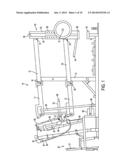
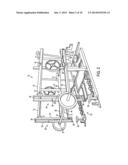
[0020] FIG. 1 is a side view of an embodiment of a weight lifting apparatus of the present application.
[0021] FIG. 2 is a perspective view of the lift station end of the embodiment of the weight lifting apparatus shown in FIG. 1.
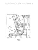
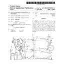
[0022] FIG. 3 is a right side view of the spotter station of an embodiment of the weightlifting apparatus.
[0023] FIG. 4 shows the weightlifting apparatus with the weight bar set at a height for bench press with a bench positioned beneath the bar.
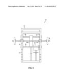
[0024] FIG. 5 is a front view of an embodiment of a weightlifting apparatus of the present application using a frame to support a linear track.
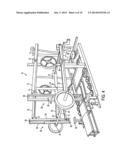
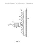
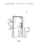
[0025] FIG. 6 is a side view of the embodiment of a weightlifting apparatus of FIG. 5.
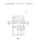
[0026] FIG. 7 is a back view of the embodiment of a weightlifting apparatus of FIGS. 5 and 6.
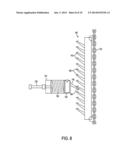
[0027] FIG. 8 is a detail view of an embodiment of a catch housing and rack with teeth.
[0028] FIG. 9 is a detail expanded view of the embodiment of a catch housing and rack with teeth of FIG. 8.
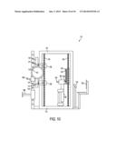
[0029] FIG. 10 is a side view of the embodiment of a weightlifting apparatus of FIGS. 5, 6, and 7 with a static weight rack attached.
DETAIL DESCRIPTION OF EMBODIMENTS
[0030] FIG. 1 is a side view of an embodiment of weightlifting apparatus 10 of the present application. This embodiment employs a cantilever rocker arm configuration duplicated on two symmetrical sides to support and control the ends of weight bar 12. Two central posts 14 each support an upper rocker arm 15 at an upper pivot 16 and a lower rocker arm 25 at a lower pivot 26. In FIG. 1, upper rocker arm 15 and lower rocker arm 25 extend from central post 14 to the right to connect to lift station frames 30. Upper rocker arm 15 and lower rocker arm 25 connect to lift station frame 30 at upper 31 and lower pivots 32 which are the same distance apart as upper pivot 16 and lower pivot 26 on central post 14. The distance between pivots 16 and 31 on upper rocker arm 15 and the distance between pivots 26 and 32 on lower rocker arm 25 are also the same. This creates a parallelogram mechanism with post 14 grounded and fixed, and lift station frame 30 moving through space as the coupler in the mechanism. Lift station 33 for a person exercising with apparatus 10 is located at lift station frames 30.
[0031] Lift station frames 30 are comprised of two vertical members rigidly attached to each other at the top and bottom to form rigid frames. A first vertical member, coupler 34, in lift station frame 30 is the member pivotally connected to upper 15 and lower 25 rocker arms with pivot joints 31 and 32, respectively. The second vertical members, bar carriers 35, of lift station frames 30 act as carriers for adjustable slides 36 that support weightlifting bar 12. Slides 36 have apertures 41 through them as do bar carriers 35 upon which they slide. Pins are inserted through these apertures to select the height of slides 36 which determines the height of bar 12. The pins may have retainers which keep them engaged through the apertures.
[0032] To the left in FIG. 1, spotter station 50 may be seen. Upper control arms 17 of upper rocker arms 15 and lower control arms 27 of lower rocker arms 25 extend to the left of vertical central post 14 as part of the control or spotter function. Spotter station 50 includes seat 51 for the person operating apparatus 10 and measuring and catch and return mechanisms, which will be discussed more with respect to other figures. Other figures will show more of lift station 33 as well as spotter station 50, the catch and return mechanisms, and the connection between the two parallelogram mechanisms at spotter station 50. In general in this application, the lift station 33 end of apparatus 10 will be referred to as the front end, or lift station end, and the spotter station 50 end of the apparatus will be referred to as the back end, back side, or spotter end.
[0033] FIG. 2 is a perspective view of the lift station 33 end of the embodiment of weightlifting apparatus 10 shown in FIG. 1. In FIG. 2, both lift station frames 30 are clearly visible. Slides 36 on bar carriers 35 support weight bar 12 with collars 37. Feet 38 at the bottom of frames 30 and caps 39 at the top of frames 30 rigidly attach the two vertical members, coupler 34 and bar carriers 35 together. Feet 38 also provide broad striking surfaces which can contact the top of pedestals 40 beneath them. Pedestals 40 provide a stop for frames 30 and prevent frames 30 from progressing further. As will be seen in later figures, the ability to adjust slides 36, and therefore the height of weight bar 12, to different heights allows apparatus 10 to accommodate many different exercises such as squat, bench press, incline press, dead lift, etc at lift station 33. Cross brace 44 spans between couplers 34 and is rigidly attached to couplers 34. Cross brace 44 provides additional stiffness to apparatus 10 at the lift station end and is in the form of a "C" to keep space for lift station 33.
[0034] FIG. 3 is a perspective view of spotter station 50 end of the embodiment of weightlifting apparatus 10 shown in FIG. 1. Lower control arms 27 are pivotally attached to each other by lower crossbeam 62 at pivots 28 and upper control arms 17 are pivotally attached to each other by upper crossbeam 61 at pivots 18. Pivots 18 and 28 are the same distance from pivots 16 and 26 respectively. This allows the parallelogram mechanisms of apparatus 10 to continue to operate, provides reinforcement of the mechanism, and produces two beams, upper crossbeam 61 and lower crossbeam 62, spanning across the space between the two parallelogram mechanisms of apparatus 10.
[0035] Upper 61 and lower 62 crossbeams spanning between upper 17 and lower 27 control arms carry catch frame 60. Catch frame 60 carries catch housing 63 which houses a portion of the catch mechanism that catches and holds apparatus 10 at the highest point weight bar 12 reaches during a lift. Catch housing 63 is generally horizontal and, in the embodiment shown, in the form of a rectangular tube. To the left in spotter station 50 in FIG. 3, a second portion of the catch mechanism is located. In the embodiment shown in FIG. 3, this second portion of the catch mechanism also has a return and reset apparatus 80. The return and reset apparatus 80 comprises screw jack 81 which is powered by electric motor 82 (see FIG. 1).
[0036] Screw jack 81 is attached to catch slide 83 which rides on guide 84. Catch bar 85 is offset from catch slide 83 and carries rack 86 with cog teeth 87 as well as slide plate 88 located above rack 86. Catch housing 63 extends horizontally from rack 86 and contains the sliding element that engages rack 86. Measuring gauge 89 is located directly on catch slide 83. Indicator 69, fixed with respect to catch housing 63 and positioned toward the top of gauge 89 in FIG. 4, moves along gauge 89 in proportion to the motion of weight bar 12 at the opposite end of apparatus 10. Screw jack 81 raises and lowers catch slide 83 and catch bar 85 with slide plate 88 and rack 86 which provides the return and reset functions of the apparatus 10. Both guide 84, which carries catch slide 83, and screw jack 81 are pivotally mounted at their bottom ends move with the motion of catch frame 60. They may also be pivoted back and forth during the maintenance of apparatus 10.
[0037] Switch 90 controls the direction of screw jack 81. Down below switch 90, power converter 99 may be seen. Power converter 99 converts from standard A/C wall socket current to a D/C current to power motor 82. However, any suitable power supply could be used, and, alternatively, other embodiments of apparatus 10 may employ different drive mechanisms or even different power systems, such as hydraulics, for the return and reset functions.
[0038] Catch housing 63 extends to the left where retention bars 64 extend from the open end of catch housing 63 past catch bar 85. Retainer pin 65 passes through apertures in retention bars 64 and behind catch bar 85. Retainer pin 65 keeps rack 86 and slide plate 88 on catch bar 85 in contact with the catch tongue in catch housing 63 while also allowing catch bar 85 with rack 86 and slide plate 88 to move up and down during the return and reset of weightlifting apparatus 10. To the right in FIG. 3, catch housing 63 terminates in a closed end.
[0039] Catch tongue 72 is located on, or attached to, a catch block located within housing 63. A spring behind the catch block biases the catch block and catch tongue 72 toward the open end of catch housing 63. Lever 93 provides a means of retracting catch tongue 72 away from catch bar 85 to disengage catch tongue 72 from rack 86.
[0040] Catch bar 85, guide 84 and catch slide 83, and screw jack 81, rock forward and catch bar 85 moves between retention bars 64. Retainer pin 65 keeps catch bar 85 in position where catch tongue 72 can engage the teeth 87 on rack 86 when weightlifting bar 12 is moved enough to align catch tongue 72 and teeth 87. Indicator 69 along with the catch housing 63 travels up and down in the opposite direction of weightlifting bar 12 due to being at the opposite end of the rocker arm configuration. Indicator 69 travels up and down on gauge 89 to indicate how far catch tongue 72 has traveled as a result of the motion of the weightlifting bar 12. The distance traveled by indicator 69 correlates to the distance traveled by weightlifting bar 12.
[0041] Gauge 89 is located directly on catch slide 83. During a lift, weightlifting apparatus 10 is set to where a lifter is bearing weightlifting bar 12 at lift station 33 at the opposite end of weightlifting apparatus 10, while slide plate 88 and rack 86 are adjusted to such a height that catch tongue 72 is pressing against slide plate 88. This adjustment of height is accomplished by screw jack 81. As the lifter performs the initial, lowering, part of the lift, catch tongue 72 slides upward on slide plate 88. As the lifter drives the weightlifting bar 12 upward, catch tongue 72 slides back down slide plate 88 past its original start position, and when the lifter explodes and releases the weight upward, catch tongue 72 will slide down off slide plate 88 to rack 86 and engage one of teeth 87 as the weight begins to return. Teeth 87 on rack 86 are shaped such that catch tongue 72 will slide downward on rack 86 past some teeth 87 but will catch as the weight begins to fall back and catch tongue 72 begins to rise.
[0042] Once catch tongue 72 has lodged in between two of teeth 87, the spotter can run screw jack 81 driven by motor 82 to allow rack 86 to lift. This is done until weightlifting bar 12 reaches a point where the lifter has assumed support and control of weightlifting bar 12 again. Once the lifter has control of the bar again, catch tongue 72 may be disengaged from rack 86 to begin to reset the position of catch bar 85 with slide plate 88 and rack 86. This disengagement and reset will be discussed with respect to a later figure.
[0043] Lever 93 moves the catch block further back into catch housing 63, disengaging catch tongue 72 from rack 86. This is done when a lifter has control of weightlifting bar 12. Screw jack 81 is then run to return catch bar 85 back to its initial position for another lift.
[0044] During an initial lift, a lifter gets into position to receive bar 12. The spotter runs screw jack 81 to allow rack 86 to rise which lowers bar 12 to the lifter. Once the lifter has control of bar 12, the spotter uses lever 93 to disengage catch tongue 72 from rack 86 and then runs screw jack 81 in the opposite direction to lower catch bar 85 until catch tongue 72 is aligned with slide plate 88 instead of rack 86. The spotter can then release lever 93 and run screw jack 81 to position indicator 69 at a start position on gauge 89. With catch tongue 72 riding on slide plate 88, the lifter may perform the complete explosive lift, including the lowering portion of the lift as well as the driving portion of the lift. At the high point of the lift, catch tongue 72 will engage rack 86. At which time, the spotter can note the position of indicator 69 on gauge 89, return the weight to the lifter, and reset catch slide 83 to its correct start position for another lift.
[0045] Returning to FIG. 1, tension adjuster bolt 68 on the back of catch housing 63 provides a way of adjusting the load of the spring within catch housing 63. As tension adjuster bolt 68 is screwed into catch housing 63, it pushes a tension block forward and compresses the spring which will drive harder against the catch block that carries catch tongue 72. To decrease tension in the spring, tension adjustment bolt 68 is backed out, which allows the tension block to move back away from open end of catch housing 63, giving the spring more room and decreasing the preload on the spring.
[0046] Returning to FIG. 1, FIG. 1 shows the entire length of catch housing 63 mounted with its open end facing toward slide plate 88 and rack 86. As the weight is lowered, the open end of the catch housing 63 will rise and catch tongue 72 will slide up slide plate 88. As the explosive lift is executed the tongue will slide down slide plate 88 to rack 86 and engage one of teeth 87.
[0047] FIG. 3 shows switch 90 which is a three position switch. Switch 90 controls screw jack 81 which raises and lowers catch bar 85 carrying slide plate 88 and rack 86. Down below the switch 90 power converter 99 may be seen. Power converter 99 converts from a standard A/C wall socket to a D/C current to drive the motor 82 of screw jack 81. However, any suitable power supply could be used.
[0048] Returning to FIG. 3, which is a right side view of the spotter station, the operation of weightlifting apparatus 10 will be described again with respect to a full view of apparatus 10 (Reference may also be made to FIG. 1). This time, a lift cycle will be described from the point where a lifter has just completed a lift. At that point the catch housing 63 has moved downward as the lift was explosively lifted upward and catch tongue 72 has engaged teeth 87 on rack 86. The spotter uses switch 90 to run screw jack 81 to allow rack 86 to move upwards. This lowers the weightlifting bar 12 until bar 12 has come into range of the lifter and the lifter can assume the control of weight bar 12. At that point, the spotter uses handle 94 which moves catch tongue 72 away from rack 86 disengaging catch tongue 72 from the teeth 87 on rack 86. While holding the handle to continue this disengagement, the spotter switches the control switch 90 to run screw jack 81 in the opposite direction to begin lowering slide plate 88 and rack 86. This downward motion is continued until slide plate 88 is in position before catch tongue 72. Handle 94 can then be released and catch tongue 72 will merely press up against slide plate 88.
[0049] The lifter then begins a lift where the weight bar 12 is lowered and then explosively lifted. As the weight bar 12 is lowered, catch tongue 72 will slide up slide plate 88, and then as weight bar 12 is lifted, catch tongue 72 will slide down slide plate 88 and on into the region of teeth 87 on rack 86. Once weight bar 12 begins to return due to gravity, catch tongue 72 will engage teeth 87 on rack 86 and be stopped. At this point, the spotter can see where on gauge 89 indicator 69 has come to rest and record it, relay the information to the lifter, or both. To begin the next cycle of lifting, the spotter toggles switch 90 to run screw jack 81 and allow rack 86 to rise upward, again lowering weight bar 12 until the lifter can assume control of weight bar 12 again.
[0050] A variety of safety mechanisms may be incorporated into the apparatus. Stop 95 on the left hand side of the apparatus is used to hold the apparatus in a static position when no exercise is being performed. Belts 96 and break 97 at the right in FIG. 1 provide a dynamic catch during a lift. If the bar begins a free fall, break 97 will clamp on belt webbing 96 and cease its movement. This will keep upper control arm 17 from continuing upward and stop apparatus 10 in position.
[0051] FIG. 2 shows weight bar without any other apparatus around it, such as when it might be used for squats. However, the height of the bar might need to be changed from that shown to be used for squats. In FIG. 1 apertures in vertical slide 36 can be used to adjust the height of weight bar 12. FIG. 4 shows the weightlifting apparatus 10 with the weight bar 12 set at a height for bench press with a bench positioned beneath bar 12. Weight bar 12 can be adjusted and set at an appropriate height for performing incline bench presses and other lifts.
[0052] FIG. 5 is a front view of an embodiment of a weightlifting apparatus 110 of the present application having a frame 112 supporting linear track 114 rather than a frame supporting a swing arm mechanism. Sled 116 rides on linear track 114. Slides 120 carry bar 118 and are adjustable up and down sled 116 to vary the operating height of bar 118. Weight bar 118 receives weight plates on its ends to vary the amount of weight a lifter is lifting.
[0053] FIG. 6 is a side view of the embodiment of weightlifting apparatus 110 shown in FIG. 5. FIG. 7 is a back view of the embodiment of weightlifting apparatus 110 shown in FIG. 6. Referring to FIG. 6, linear track 114 is vertically oriented on frame 112. Sled 116 is coupled to linear track 114 and moves up and down linear track 114 on rollers 117 which provide low friction motion of sled 116.
[0054] Chains 124 wrap around frame 112 in continuous loops, front to back, which is to say that the loops run up the front of the frame, along the top to the back, along the bottom to the front again (as opposed to side to side). In the embodiment of FIGS. 5-7, there are two chains 124, one at each side of frame 112. Two sprockets 126 are located at the top of frame 112 and two sprockets 126 are located at the bottom of frame 112. Sled 116 is attached to chains 124 with couplers 128. Sprockets 126 allow chains 124 to move smoothly with the motion of sled 116.
[0055] Referring now to FIG. 7, upper crossbeam 130 and lower crossbeam 132 span the back of frame 112. Catch bar 134 spans between upper crossbeam 130 and lower crossbeam 132 and catch bar 134, upper crossbeam 130, and lower crossbeam 132 form catch frame 136. Upper crossbeam 130 and lower crossbeam 132 attach to chains 124 at their ends 138. Catch frame 136 moves in the opposite vertical direction from sled 116. As sled 116 is moved upward, catch frame 136 moves downward, and vice versa.
[0056] Referring back to FIG. 6, rack 140 with teeth 142 can be seen protruding into the interior of frame 112. Rack 140 is carried on catch bar 134. Catch housing 144 is mounted on return and reset mechanism 146 in proximity to rack 140. Tongue 148 extends from catch housing 144 and is spring biased toward rack 140.
[0057] A spotter sits in seat 150 at console 152 and operates return and reset mechanism 146. Return and reset mechanism 146 is set at a height where tongue 148 will engage teeth 142 on rack 140 when a lift is completed. When a lifter in control of bar 118 executes a lift by lowering bar 118 and then explosively lifting bar 118 to where it rises free of the lifter, rack 140 will descend to align with tongue 148 which will engage one of teeth 142 when the bar 118 begins to descend again. This stops bar 118 by stopping catch frame 136 which is connected to sled 116 and bar 118 via chains 124.
[0058] Once tongue 148 engages rack 140 and stops bar 118, a spotter can raise return and reset mechanism 146 and catch housing 144 until bar 118 is returned to the control of the lifter. Once return and reset mechanism 146 is raised to that height, the spotter retracts tongue 148 from rack 140 and maintains tongue 148 in a disengaged position while lowering return and reset mechanism 146 past rack 140. Once it is past rack 140, the spotter releases tongue 148. Return and reset mechanism 146 may be a screw jack, hydraulic cylinder, or other mechanism. Additionally, other embodiments of weightlifting apparatus 110 may incorporate controls at sprockets 126 to assist in the control of sled 116 and bar 118.
[0059] FIGS. 8 and 9 are detail views of an embodiment of catch housing 144 and rack 140 with teeth 142. In FIGS. 8 and 9, catch housing 144 is shown in sectional view. Catch tongue 148 extends from catch block 154 and spring 156 biases catch block to extend from catch housing 144. Tension adjuster 158 at the back of catch housing 144 allows the preload on spring 156 to be adjusted.
[0060] The embodiments of tongue 148 and rack 140 in FIGS. 8 and 9 include an additional safety feature. Hooks 160 on the end of tongue 148 and teeth 142 provide an interlocking function. If a spotter tries to retract tongue 148 from rack 140 before return and reset mechanism 146 has lifted catch housing 144 high enough to clear hooks 160 on tongue 148 and teeth 142, hooks 160 on tongue 148 and teeth 142 will interlock as tongue 148 is withdrawn. In FIG. 8, tongue 148 is withdrawn as catch housing 144 is lifted past the point where the lifter has taking control of bar 118. In FIG. 9, tongue 148 is not contacting rack 140 and therefore the lifter has taken control of bar 118 which is why rack 140 is maintaining its position without contact from tongue 148. However, if tongue 148 is retracted without simultaneously lifting catch housing 144, hooks 160 will interlock and prevent the full disengagement of tongue 148 from rack 140. This feature requires that tongue 148 be intentionally disengaged from rack 140.
[0061] FIG. 10 is a side view of the embodiment of a weightlifting apparatus of FIGS. 5, 6, and 7 with a static weight rack attached. Both upper rack 166 and lower rack 138 are adjustable to different heights using apertures 170. Upper rack 166 holds a free weight bar previous to a lifter taking the bar. Lower rack 168 catches the bar should a lifter fail a lift or drop the bar. Addition of a static weight rack increases the versatility of the embodiment shown in FIGS. 5-7 and 10 without affecting the ability to perform explosive lift training with the dynamic portion of the apparatus.
[0062] Although specific embodiments of the invention have been described with specificity, the embodiments described should not be considered exhaustive of the possible embodiments of the invention and should not be held as limiting the scope and range of the claims. Similarly the drawings are not exhaustive depictions of embodiments of the invention and the abstract is intended to allow a person to quickly gain the general field of the invention and should not be taken as limiting the scope of the claims.
User Contributions:
Comment about this patent or add new information about this topic:
| People who visited this patent also read: | |
| Patent application number | Title |
|---|---|
| 20140242829 | CONNECTOR WITH MECHANICAL CONNECT-ASSIST AND RETENTION |
| 20140242828 | SECURING DEVICE FOR SECURING PLUG OF TRANSMISSION CABLE WITH CONNECTOR |
| 20140242827 | Electrical Connector |
| 20140242826 | LATCHING MECHANISMS FOR PLUGGABLE ELECTRONIC DEVICES |
| 20140242825 | SYSTEM AND METHOD FOR CONNECTING A POWER CABLE WITH A SUBMERSIBLE COMPONENT |
Images included with this patent application:
 |  |
 |  |
 |  |
 |  |
 |  |
 |
| Similar patent applications: | |
| Date | Title |
|---|---|
| 2011-03-17 | Body mounted muscular brace |
| 2012-09-20 | Waist and hip developer |
| 2013-05-02 | Waist and hip developer |
| 2014-03-27 | Waist and hip developer |
| 2014-05-29 | Muscle development system |
| New patent applications in this class: | |
| Date | Title |
|---|---|
| 2018-01-25 | Injection molded eva foam barbell pad |
| 2016-06-09 | Weight training structures |
| 2016-04-21 | Exercising apparatus |
| 2016-03-17 | Fitness structure |
| 2016-02-18 | Weight training apparatus and method of using |
| Top Inventors for class "Exercise devices" | |
| Rank | Inventor's name |
|---|---|
| 1 | William T. Dalebout |
| 2 | Scott R. Watterson |
| 3 | Raymond Giannelli |
| 4 | Leao Wang |
| 5 | Bruce Hockridge |