Patent application title: REFRIGERATION APPLIANCE WITH TWO EVAPORATORS IN DIFFERENT COMPARTMENTS
Inventors:
Cesare Maria Joppolo (Comerio, IT)
Luca Molinaroli (Comerio, IT)
Matej Visek (Comerio, IT)
Assignees:
WHIRLPOOL CORPORATION
IPC8 Class: AF25B700FI
USPC Class:
62335
Class name: Refrigeration plural paired different function refrigeration producing elements, e.g., cascade
Publication date: 2014-05-15
Patent application number: 20140130536
Abstract:
A refrigerator having a refrigerating circuit with a compressor, a
condenser and two evaporators placed in different compartments of the
appliance comprises valve means for alternatively directing refrigerant
flow towards one of the evaporators. One of the evaporators is in heat
exchange relationship with a phase change materialClaims:
1. A refrigeration circuit for a refrigeration appliance comprising: a
compressor, a condenser, a first evaporator is in a first refrigeration
compartment of the refrigeration appliance, a second evaporator is in a
second refrigeration compartment of the refrigeration appliance, flow
directing means in fluid contact with the first and second evaporators,
wherein the flow directing means alternatively directs refrigerant flow
towards one of the evaporators, and wherein at least one of the
evaporators is in a heat exchange relationship with a phase change
material.
2. The refrigeration circuit of claim 1, further comprising a second flow directing means adapted to divert refrigerant flow towards an auxiliary circuit, wherein said auxiliary circuit is in heat exchange relationship with said phase change material, and wherein said heat exchange relationship sub-cools the refrigerant.
3. The refrigeration circuit of claim 2, wherein said auxiliary circuit is: downstream the phase change material, and further comprises an expansion device which is upstream the evaporator that is in the heat exchange relationship with the phase change material.
4. The refrigeration circuit of claim 3 wherein upstream the evaporator that is in the heat exchange relationship with the phase change material is in a refrigeration compartment.
5. The refrigeration circuit of claim 2 wherein upstream the evaporator that is in the heat exchange relationship with the phase change material is in a refrigeration compartment.
6. The refrigeration circuit of claim 1, wherein the flow directing means comprises a valve.
7. The refrigeration circuit of claim 1, wherein the flow directing means is a three-way electro valve.
8. The refrigeration circuit of claim 2, wherein the second flow directing means comprises a valve
9. The refrigeration circuit of claim 2, wherein the second flow directing means is a three-way electro valve.
10. A refrigeration circuit for a refrigeration appliance comprising: a compressor, a condenser, a first evaporator is in a first refrigeration compartment of the refrigeration appliance, a second evaporator is in a second refrigeration compartment of the refrigeration appliance, a valve that fluidically connects the compressor to the two evaporators and wherein the valve further directs flow of refrigerant to only one of the two evaporators at a time, and wherein at least one of the evaporators is in thermal contact with a phase change material.
11. The refrigeration circuit of claim 10, further comprising: an auxiliary circuit, wherein said auxiliary circuit is in heat exchange relationship with said phase change material, and wherein said heat exchange relationship sub-cools the refrigerant, and a second valve, wherein the second valve is adapted to divert refrigerant flow towards the auxiliary circuit,
12. The refrigeration circuit of claim 11, wherein: said evaporator that is in the heat exchange relationship with the phase change material is: the first evaporator, and is in a refrigeration compartment; and said auxiliary circuit is: downstream the phase change material, and further comprises an expansion device; wherein the expansion device is upstream the first evaporator.
13. A refrigeration circuit for a refrigeration appliance comprising: a compressor, a condenser, a refrigeration evaporator in a refrigeration compartment of the refrigeration appliance, the refrigeration evaporator in thermal contact with a phase change material, a freezer evaporator in a freezer compartment of the refrigeration appliance, an auxiliary circuit, wherein said auxiliary circuit is; downstream the phase change material, and further comprises an expansion device; wherein the expansion device is upstream the refrigeration evaporator. a first valve in the refrigerant flow path of between the compressor and the freezer and refrigerator evaporators, and wherein the valve further directs flow of refrigerant to only one of the two evaporators at a time, and a second valve, wherein the second valve is adapted to divert refrigerant flow towards the auxiliary circuit.
14. The refrigeration circuit of claim 13, wherein the first valve is a three-way electro valve.
15. The refrigeration circuit of claim 14, wherein the second valve is a three-way electro valve.
16. The refrigeration circuit of claim 13, wherein the second valve is a three-way electro valve.
Description:
BACKGROUND OF THE INVENTION
[0001] The present invention relates to a refrigeration appliance having a refrigerating circuit with a compressor, a condenser and at least two evaporators placed in different compartments of the appliance, a three-way valve being provided for alternatively directing the refrigerant flow towards one of the two evaporators.
SUMMARY OF THE INVENTION
[0002] The above kind of refrigerating circuit is also known as "sequential dual evaporator" (SDE) system and allows the design of refrigerators having high energy efficiency.
[0003] It is an object of the present invention to further enhance energy efficiency of refrigeration appliances using the SDE cycle. Another object of the present invention is to stabilize temperature in the refrigeration compartment where one of the evaporators is placed.
[0004] The above objects are reached tanks to the features listed in the appended claims.
[0005] According to the invention, energy consumption improvement is reached by introducing a phase change material (PCM) in contact with the first evaporator inside the refrigeration compartment. According to a preferred embodiment of the invention and additional sub-cooling loop is provided for shifting cooling capacity from refrigeration compartment to freezer compartment. As phase change material any suitable composition can be used which has a liquid-solid phase change temperature below temperature of the refrigeration compartment and high enough to avoid freezing in the refrigeration compartment at minimum load. Example of suitable PCMs can be mixtures of water and glycol or eutectic gels. According to the invention, temperature of the refrigeration compartment becomes more stabilized because of higher thermal capacity of such compartment and therefore an extended ON/OFF period of the compressor is obtained. According to a further preferred embodiment, a second electro valve is used downstream the first in order to avoid additional heat gains of the appliance. Such second electro valve allows decision making when to use a sub-cooling loop or not. The system design according to the invention also offers a possibility of quick defrosting the first evaporator (i.e. the evaporator of the refrigeration compartment).
[0006] Further features and advantages according to the present invention will become clear from the following description, with reference to the attached drawings.
BRIEF DESCRIPTION OF THE SEVERAL VIEWS OF THE DRAWINGS
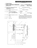
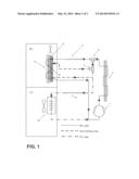
[0007] FIG. 1 is a schematic view of the refrigeration circuit according to a first embodiment of the invention;
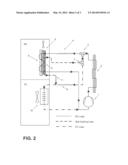
[0008] FIG. 2 is a view similar to FIG. 1 and referring to a second embodiment of the invention, and
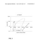
[0009] FIG. 3 is a diagram pressure vs. specific enthalpy showing the thermodynamic effect of the sub-cooling according to the invention on the cooling capacity.
DETAILED DESCRIPTION OF THE INVENTION
[0010] With reference to FIG. 1, a sequential dual evaporator system is shown with a first evaporator 6 used in the refrigeration compartment RC and a second evaporator 10 used in the freezer compartment FC. System comprises also a shared compressor 1, a condenser 2 followed by a bi-stable electro-valve 3 directing flow either to the first evaporator 6 or to the second evaporator 10. Each evaporator has dedicated capillary tube, respectively 4 for the first evaporator 6 and 9 for the second evaporator 10. Of course any expansion device different from a capillary tube can be used as well. The first evaporator 6 is connected to a reservoir or container 5 of phase change material. During the operation of RC evaporator 6 the PCM 5 is charged. When FC evaporator 10 is switched ON (i.e. by diverting the flow towards the evaporator 10 by means of the electro valve 3) the liquid refrigerant is directly expanded in capillary 9 (in the configuration where the second electro valve 7 does not divert the flow into the sub-cooling loop.
[0011] It is important to notice that in having a sub-cooling PCM 8 inside of the refrigeration compartment RC additional appliance heat gains from ambient are avoided. Sub-cooling loop enters the refrigeration compartment RC and exchanges heat with PCM in such compartment. The second bi-stable electro-valve 7 is placed on the FC loop to allow switching ON and OFF of the sub-cooling loop. Operation of the loop is decided according to the amount of cooling capacity accumulated in PCM or RC evaporator request for defrost operation. Higher sub-cooling during FC operation results in higher cooling capacity delivered to FC evaporator 10 with the assumption of unchanged refrigerant mass-flow. This gain in cooling capacity is shown in FIG. 3. According to the embodiment shown in FIG. 2, the sub-cooling loop may contain a dedicated capillary tube 11 or any kind of expansion device placed after the PCM reservoir to properly match refrigerant mass-flow rate at high sub-cooling. One of the main advantages of the present invention derives from the PCM contact with the evaporator 6 of the refrigeration compartment RC. This contact improves the global heat transfer coefficient of such evaporator and therefore it allows operation of the RC refrigeration loop at increased evaporator temperatures and increased compressor COP (coefficient of performance). During the RC loop operation, cooling capacity is accumulated in the PCM and continuously released to the refrigeration compartment RC by means of natural convection or a variable speed air fan at a relatively small rate.
[0012] In case the PCM in the refrigeration compartment contains a sufficient amount of accumulated cooling capacity, it can be used during the operation of the freezer evaporator 10 to additionally sub-cool liquid by switching ON the sub-cooling loop. Sub-cooling loop can also contain expansion valve (not shown) to partially expand the liquid refrigerant before entering sub-cooling heat exchanger. Increased cooling capacity is delivered to the refrigeration compartment FC, which decreases FC loop time and energy consumption.
[0013] Sub-cooling loop acts also as a quick defrost of the evaporator 6 in cases when set phase change temperature is significantly below 0° C. and there is a risk of frost accumulation.
User Contributions:
Comment about this patent or add new information about this topic:
Images included with this patent application:
 |  |
 |  |
| Similar patent applications: | |
| Date | Title |
|---|---|
| 2014-08-07 | Hybrid apparatus for drying a flow of compressed gas |
| 2012-10-25 | Adaptable evaporator defrost logic |
| 2011-08-18 | Chiller with setpoint adjustment |
| 2014-07-31 | Refrigeration apparatus |
| New patent applications in this class: | |
| Date | Title |
|---|---|
| 2016-06-23 | Refrigeration apparatus |
| 2016-03-24 | Overlapping type freezing-force circulation refrigeration unit (high pressure side) |
| 2015-05-28 | Combination phase separator and drier for a refrigeration appliance |
| 2015-05-07 | Refrigeration cycle of refrigerator |
| 2014-09-18 | Air-conditioning apparatus |
| Top Inventors for class "Refrigeration" | |
| Rank | Inventor's name |
|---|---|
| 1 | Michael F. Taras |
| 2 | Alexander Lifson |
| 3 | Koji Yamashita |
| 4 | Hiroyuki Morimoto |
| 5 | Patrick J. Boarman |