Patent application title: FALL-PROTECTION SYSTEM AND METHOD
Inventors:
Arthur Lewis Gelston (Montreal, CA)
Robert Salasidis (St. Laurent, CA)
Emin Agassi (Blue Bell, PA, US)
IPC8 Class: AA41D3100FI
USPC Class:
2455
Class name: Apparel guard or protector
Publication date: 2014-05-08
Patent application number: 20140123374
Abstract:
A fall-protection system and method are described. The system has at
least one sensor for sensing if the person is falling and for outputting
a status signal. The system also has a processor configured for receiving
the status signal from the at least one sensor, and for outputting a
corresponding command signal. The system also has a support for the at
least one sensor and the processor, the support being portable by the
person. The system also has a fall-protection device mountable to the
support and configured for receiving the command signal from the
processor. The fall-protection device has inflatable membranes, at least
some of which are deployable as elongated extensions so to protect a part
of the person by forming a substantially flower-like enclosure before
said part contacts the ground surface. The fall-protection device is
deployable upon the processor outputting a command signal indicative that
the person is falling.Claims:
1. A fall-protection system for reducing risk of possible injury to a
person in a sitting or standing position resulting from a fall against a
ground surface, the system comprising: at least one sensor for sensing if
the person is falling and for outputting a status signal; a processor
configured for receiving the status signal from the at least one sensor,
and for outputting a corresponding command signal; a support for the at
least one sensor and the processor, the support being portable by the
person; and a fall-protection device mountable to the support and
configured for receiving the command signal from the processor, the
fall-protection device comprising a plurality of deployable inflatable
membranes, at least some of the inflatable membranes being deployable as
elongated extensions so as to form a substantially flower-like enclosure
about a part of the person so as to protect said part of the person
before said part contacts the ground surface, the inflatable membranes
being deployable upon the processor outputting a command signal
indicative that the person is falling, thereby reducing risk of possible
injury to the person resulting from the fall.
2. A fall-protection system according to claim 1, wherein the at least one sensor comprises at least one accelerometer for outputting a status signal indicative of an acceleration of the person or the part with respect to the ground surface.
3. A fall-protection system according to claim 2, wherein the at least one sensor further comprises at least one vertical-deviation sensor for outputting a status signal indicative of a deviation of the person or the part from a vertical plane.
4. A fall-protection system according to claim 1, wherein at least one inflatable membrane inflates away from the person or the part upon the processor outputting the command signal indicative that the person is falling.
5. A fall-protection system according to claim 1, wherein at least one inflatable membranes encloses, at least partially, at least one of the head and neck of the person, and the hips and posterior of the person, upon being inflated.
6. A fall-protection system according to claim 1, wherein at least one inflatable membrane forms a substantially cocoon-like enclosure at least partially about at least one of the head and neck of the person, and the hips and posterior of the person, upon being inflated.
7. A fall-protection system according to claim 1, wherein the support comprises an accessory for being worn by the person.
8. A fall-protection system according to claim 7, wherein the accessory comprises a belt for being worn about the midsection of the person, and a headband for being worn about the head of the person.
9. A fall-protection system according to claim 8, wherein the at least one sensor comprises at least one accelerometer secured to the headband, and at least one vertical-deviation sensor secured to the belt.
10. A fall-protection system according to claim 8, wherein the processor and a monitoring station are secured to the belt.
11. A fall-protection system according to claim 8, wherein the inflatable membranes are mountable to the belt and spaced apart from one another, at least two inflatable membranes being inflatable toward the head and neck of the person upon the belt being worn by the person and the processor outputting the command signal indicative that the person is falling.
12. A fall-protection system according to claim 8, wherein the inflatable membranes are mountable to the belt and spaced apart from one another, at least one inflatable membrane being inflatable about the hips and posterior of the person upon the belt being worn by the person and the processor outputting the command signal indicative that the person is falling.
13. A fall-protection system according to claim 8, wherein at least one inflatable membrane is mountable to the headband, the at least one inflatable membrane being inflatable about the head and neck of the person upon the headband being worn by the person and the processor outputting the command signal indicative that the person is falling.
14. A fall-protection system according to claim 1, wherein the status signal is indicative of a status of the person selected from the group consisting of: an acceleration of the person or the part, a deviation of the person or the part from a vertical plane, a removal of the fall-protection device from the person, a removal of the at least one sensor from the person, a low power state for the fall-protection device, a powering-off of the fall-protection device, an indication that the person is lying down, and a deployment of the inflatable membranes.
15. A method for reducing risk of possible injury to a person in a sitting or standing position resulting from a fall against a ground surface, the method comprising the steps of: a) sensing if the person is falling by measuring an acceleration of the person or part, and by measuring a deviation of the person or part from a vertical plane; b) outputting a command signal; and c) deploying a plurality of inflatable membranes, at least some of the inflatable membranes being deployable about a part of the person so as to form a substantially flower-like enclosure when the command signal is indicative of the person falling, so as to protect said part of the person before said part contacts the ground surface, thereby reducing risk of possible injury to the person resulting from the fall.
16. A method according to claim 15, wherein step a) comprises outputting a status signal indicative of a status of the person, the status signal being selected from the group consisting of: an acceleration of the person or the part, a deviation of the person or the part from a vertical plane, a removal of the inflatable membranes from the person, a low power state for the inflatable membranes, a powering-off of the inflatable membranes, an indication that the person is lying down, and a deployment of the inflatable membranes.
17. A method according to claim 15, wherein step b) comprises generating a trigger condition before outputting the command signal upon the acceleration of the person or part being less than about 1 g.
18. A method according to claim 15, further comprising at least partially enclosing at least one of the head and the midsection of the person with at least one inflatable membrane.
19. A method according to claim 15, further comprising communicating at least one of the following to a monitoring station: health and personal information concerning the person, deployment of the inflatable membranes, the command signal, the acceleration of the person or the part, the deviation of the person or the part from the vertical plane, a removal of the inflatable membranes from the person, a low power state for the inflatable membranes, a powering-off of the inflatable membranes, and an indication that the person is lying down.
Description:
CROSS-REFERENCE TO RELATED APPLICATIONS
[0001] This application claims priority from U.S. Provisional Application No. 61/796,277 filed on Nov. 7, 2012 and entitled "Personal Falls Protection Device", the entirety of which is hereby incorporated by reference.
BACKGROUND OF THE INVENTION
[0002] There is a need to reduce the annual societal burden caused by falls in the geriatric and disabled population, to name but one example of an affected demographic. This burden will increase in the immediate term in proportion to the impending expansion of the geriatric population as the baby-boom generation exits middle age.
[0003] In 2010, more than 600,000 falls resulted in hospitalization in the United States alone. The medical care associated with these falls can be costly, and can range from about $5,000 to about $13,000 per incident, resulting in expenses in excess of $1 billion. These numbers are likely to increase in the medium and long term, and do not even include those falls which, tragically, are fatal.
[0004] Some examples of devices in this field are described in the following documents: U.S. Pat. No. 5,464,250; U.S. Pat. No. 6,073,961; U.S. Pat. No. 6,546,561 B2; and U.S. Pat. No. 6,616,177 B2.
[0005] The Applicants are also aware of a 2013 student project from students of Simon Fraser University in Vancouver, British Columbia, Canada. The project is entitled "Multiple Use Wheelchair Airbag System", and lists the group members as Paul Yoon, David Gunther, Jason Chan, Philip Chan, and the supervisor as Assistant Professor Siamak Arzanpour.
[0006] Some of the following disadvantages may be associated with known systems and devices for protecting against falls: a) they may not be single, integrated systems and thus may be too cumbersome to be kept in proximity to a person; b) they may not be able to protect the person before they impact the ground; c) they may require manual activation, which renders them less useful for people with low levels of dexterity; d) etc.
[0007] Hence, in light of the aforementioned, there is a need for a device which, by virtue of its design and components, would be able to overcome or at least minimize some of the aforementioned prior art drawbacks.
SUMMARY OF THE INVENTION
[0008] One object of the present invention is to provide an improvement to existing conventional systems.
[0009] In accordance with a general aspect, there is provided a fall-protection system for reducing risk of possible injury to a person in a sitting or standing position resulting from a fall against a ground surface, the system comprising:
[0010] at least one sensor for sensing if the person is falling and for outputting a status signal;
[0011] a processor configured for receiving the status signal from the at least one sensor, and for outputting a corresponding command signal;
[0012] a support for the at least one sensor and the processor, the support being portable by the person; and
[0013] a fall-protection device mountable to the support and configured for receiving the command signal from the processor, the fall-protection device comprising a plurality of deployable inflatable membranes, at least some of the inflatable membranes being deployable as elongated extensions so as to form a substantially flower-like enclosure about a part of the person so as to protect said part of the person before said part contacts the ground surface, the inflatable membranes being deployable upon the processor outputting a command signal indicative that the person is falling, thereby reducing risk of possible injury to the person resulting from the fall.
[0014] In some embodiments, the at least one sensor has at least one accelerometer for outputting a status signal indicative of an acceleration of the person or the part with respect to the ground surface. Further optionally, the at least one sensor further can have at least one vertical-deviation sensor for outputting a status signal indicative of a deviation of the person or the part from a vertical plane.
[0015] In some embodiments, the fall-protection device has at least one inflatable membrane. The at least one inflatable membrane may inflate away from the person or the part upon the processor outputting the command signal indicative that the person is falling. The at least one inflatable membranes may also enclose, at least partially, at least one of the head and neck of the person, and the hips and posterior of the person, upon being inflated. The at least one inflatable membrane can form a substantially cocoon-like or flower-like enclosure at least partially about at least one of the head and neck of the person, and the hips and posterior of the person, upon being inflated.
[0016] In some embodiments, the support has an accessory for being worn by the person. The accessory can include a pair of shorts for being worn about the midsection of the person, and a headband for being worn about the head of the person. The fall-protection device can include a first inflatable membrane housed within the pair of shorts and a second inflatable membrane mountable to the headband, the first and second inflatable membranes being inflatable about the hips and posterior of the person, and about the head and neck of the person, respectively, upon the processor outputting the command signal indicative that the person is falling.
[0017] The accessory can also include a belt for being worn about the midsection of the person, and a headband for being worn about the head of the person. The at least one sensor can have at least one accelerometer secured to the headband, and at least one vertical-deviation sensor secured to the belt. Further optionally, the processor and a monitoring station can be secured to the belt. The fall-protection device can also include a plurality of inflatable membranes mountable to the belt and spaced apart from one another, at least two inflatable membranes being inflatable toward the head and neck of the person upon the belt being worn by the person and the processor outputting the command signal indicative that the person is falling. The fall-protection device can also include a plurality of inflatable membranes mountable to the belt and spaced apart from one another, at least one inflatable membrane being inflatable about the hips and posterior of the person upon the belt being worn by the person and the processor outputting the command signal indicative that the person is falling. Further optionally, the fall-protection device can include at least one inflatable membrane mountable to the headband, the at least one inflatable membrane being inflatable about the head and neck of the person upon the headband being worn by the person and the processor outputting the command signal indicative that the person is falling.
[0018] In some embodiments, the status signal is indicative of a status or parameter of the person and/or fall-protection device selected from the group consisting of: an acceleration of the person or the part, a deviation of the person or the part from a vertical plane, a removal of the fall-protection device from the person, a removal of the at least one sensor from the person, a low power state for the fall-protection device, a powering-off of the fall-protection device, an indication that the person is lying down, and a deployment of the fall-protection device.
[0019] In some embodiments, the fall-protection system can include a monitoring station for receiving the status signal and the command signal. The monitoring station is a wireless device configured for receiving the status signal and the command signal wirelessly.
[0020] According to another general aspect, there is provided a method for reducing risk of possible injury to a person in a sitting or standing position resulting from a fall against a ground surface, the method comprising the steps of:
[0021] a) sensing if the person is falling by measuring an acceleration of the person or part, and by measuring a deviation of the person or part from a vertical plane;
[0022] b) outputting a command signal; and
[0023] c) deploying a plurality of inflatable membranes, at least some of the inflatable membranes being deployable about a part of the person so as to form a substantially flower-like enclosure when the command signal is indicative of the person falling, so as to protect said part of the person before said part contacts the ground surface, thereby reducing risk of possible injury to the person resulting from the fall.
[0024] In some embodiments, step a) includes outputting a status signal indicative of a status or parameter of the person and/or fall-protection device, the status signal being selected from the group consisting of: an acceleration of the person or the part, a deviation of the person or the part from a vertical plane, a removal of the fall-protection device from the person, a low power state for the fall-protection device, a powering-off of the fall-protection device, an indication that the person is lying down, and a deployment of the fall-protection device. Step a) can further include outputting the status signal at discrete intervals.
[0025] In some embodiments, step b) includes generating a trigger condition before outputting the command signal upon the acceleration of the person or part being less than about 1 g.
[0026] In some embodiments, step c) includes inflating the fall-protection device about the part of the person.
[0027] In some embodiments, the method can include at least partially enclosing at least one of the head and the midsection of the person with the fall-protection device.
[0028] In some embodiments, the method can include communicating at least one of the following to a monitoring station: health and personal information concerning the person, deployment of the fall-protection device, the command signal, the acceleration of the person or the part, the deviation of the person or the part from the vertical plane, a removal of the fall-protection device from the person, a low power state for the fall-protection device, a powering-off of the fall-protection device, and an indication that the person is lying down. Optionally, the communicating can include communicating wirelessly.
[0029] The components, advantages and other features of the system and method will become more apparent upon reading the following non-restrictive description of some optional configurations, given for the purpose of exemplification only, with reference to the accompanying drawings.
BRIEF DESCRIPTION OF THE DRAWINGS
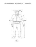
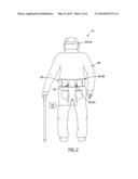
[0030] FIG. 1 is a front view of a person wearing a fall-protection system, according to an optional embodiment.
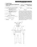
[0031] FIG. 2 is a rear view of the person and the fall-protection system of FIG. 1.
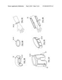
[0032] FIG. 3A is a perspective view of an inflatable membrane housed within a pair of shorts and being shown as deployed about the pair of shorts, according to another optional embodiment. FIG. 3B is a partial cross-sectional perspective view of an inflatable membrane being shown as deployed about a headband, according to yet another optional embodiment.
[0033] FIGS. 4A and 4B are perspective views of a belt and a headband, respectively, of a fall-protection system, according to yet another optional embodiment.
[0034] FIG. 5A is a perspective view of an armband worn on the arm of a person, according to yet another optional embodiment. FIG. 5B is a partial cross-sectional perspective view of an inflatable membrane being shown as deployed about the armband of FIG. 5A.
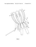
[0035] FIG. 6 is a perspective view of inflatable membranes being shown as deployed about a belt, according to yet another optional embodiment.
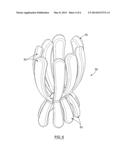
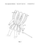
[0036] FIG. 7 is a front perspective view of a person in fall, a fall-protection device of a fall-protection system being shown as deployed, according to another optional embodiment.
[0037] FIG. 8 is a rear perspective view of what is shown in FIG. 7.
DETAILED DESCRIPTION OF THE EMBODIMENTS
[0038] In the following description, the same numerical references refer to similar elements. Furthermore, for the sake of simplicity and clarity, namely so as to not unduly burden the figures with several references numbers, not all figures contain references to all the components and features, and references to some components and features may be found in only one figure and components and features of the present invention illustrated in other figures can be easily inferred therefrom. The embodiments, geometrical configurations, materials mentioned and/or dimensions shown in the figures are optional, and are given for exemplification purposes only.
[0039] Furthermore, although the present invention may be used for injury-preventing or reduction purposes, such as protection against falls, for example, and as a result, is sometimes described in the context of a possible use for protecting people from the risk of injury which may result from falling down, it is understood that it may be used for other purposes and/or activities. One of many possible such uses include protecting a person or part from accelerating or impacting a wall or surface. For this reason, expressions such as "fall", "person", "protection", "ground surface", etc. as used herein should not be taken as to limit the scope of the present invention. These expressions encompass all other kinds of materials, objects and/or purposes with which the present invention could be used and may be useful, as can be easily understood.
[0040] Broadly described, the fall-protection system 10 (or simply "system 10"), an example of which is shown in FIGS. 1 and 2, allows for the detection of an imminent physical fall of a person 60 who is in a standing position (i.e. walking or moving upright) or a sitting position, for the deployment of devices to protect the person 60 before she or he impacts a ground surface, and can also allow for this and other events to be communicated to support systems. The system 10 can thus be used to reduce the risk of injury which may result should the person 60 fall against the ground surface.
[0041] The system 10 can be used by many different people. In some possible applications, the system 10 can be used by patients in a medical facility who suffer from gait disturbances, cognitive problems, or degenerative neurological conditions. In other possible applications, the system 10 can be used by the elderly who may be at a heightened risk of being injured through falls. In yet some more possible applications, the system 10 can be used by people who have already suffered an injury and are recovering, and who need to protect a specific part or parts of the body from further injury. The system 10 can also be used to protect people from fall injuries whether they are sitting down, or standing upright. It can thus be appreciated that the system 10 can be used by a wide variety of people, and for a wide variety of purposes.
[0042] The system 10 has one or more sensors 20, examples of which are shown in FIGS. 1 and 2. The sensors 20 detect whether the person 60 is falling, and also output a status signal. In most embodiments, but not necessarily all, the sensors 20 are worn on or near strategic parts of the body of the person 60 so as to better detect an impending fall of the person 60. Since the sensors 20 can be any device which receive a signal or stimulus, and output the status signal, it will be appreciated that their ability to detect whether the person 60 is falling can be accomplished in many different ways.
[0043] In some embodiments, the sensors 20 can include one or more accelerometers 22. The accelerometers 22 can measure the acceleration of the person 60, or of a specific part or portion of the person 60, in any suitable direction. If the measured acceleration value suggests that the person 60 or the part is falling toward the ground surface, the accelerometer 22 will output a status signal that is indicative of this. In so doing, the accelerometer advantageously allows for the automatic monitoring of the person's 60 stability, and the automatic signaling of whether the person 60 may fall and impact the ground surface. In most embodiments, the outputting of the status signal which is indicative of the person 60 or part falling to the ground may depend on the measurement of a threshold or trigger condition by the accelerometer 22. For example, the accelerometer 22 can output the status signal if the directionality of the measured acceleration indicates the person 60 is falling towards the ground surface, and if the measured acceleration value is less than about 1 g. Further optionally, the accelerometer 22 can output the status signal if the measured acceleration value is between about 0.3 g to about 0 g. Of course, other trigger conditions can be provided to the accelerometer 22 and are within the scope of the present disclosure.
[0044] In some embodiments, the system 10 can have redundancy measures to ensure the accuracy of the accelerometer 22, and to validate that the person 60 or part is falling toward the ground surface. One of these measures can include a vertical-deviation sensor 24, such as a gyroscope or inclinometer, which can measure the deviation of the person 60 or part from a vertical plane, and thus, the "verticality" of the person 60. Such verticality can be measured whether the person 60 is sitting, or standing upright. As with the accelerometer 22, the vertical-deviation sensor 24 can include or be programmed with a trigger condition so that the vertical-deviation sensor 24 is commanded to output a signal when the vertical deviation of the person 60 or part surpasses a suitable trigger or threshold value. Such a trigger value can depend on some of the following non-exhaustive list of factors: the nature or condition of the person 60 using the system 10, the environment in which the system 10 is used, the rapidity with which the fall-protection device can be deployed, the risk and consequences of potential injury resulting from a fall of the person 60, etc.
[0045] It can thus be appreciated that the use of both an accelerometer 22 and a vertical-deviation sensor 24 provides a measure of redundancy, thereby advantageously contributing to safety, and further advantageously preventing false-positives from deploying the fall-protection device described below. Indeed, the following example may better facilitate comprehension of this redundancy. If the person 60 or part makes a sudden, vertical movement of their head towards the ground surface, the accelerometer 22 may output a status signal indicative of the person 60 falling toward the ground, regardless of whether the person 60 is actually falling. The vertical-deviation sensor 24 in such an example may prevent the deployment of the fall-protection device because it can sense that the person's body has not deviated beyond an acceptable threshold from the vertical plane, and is thus not falling toward the ground surface. Similarly, the vertical-deviation sensor 24 may show that the person 60 has deviated beyond an acceptable threshold from the vertical, but is not actually falling towards the ground surface. In such a situation, the accelerometer 22 can confirm that the person 60 is not falling toward the ground surface, thus preventing deployment of the fall-protection device.
[0046] The status signals can be outputted and random or set intervals of time, upon an event occurring, or according to any other condition set for the system 10. In addition to the status signals mentioned above, the sensors 20 can output other status signals. One possible status signal can alert a health professional or monitoring station that the system 10 and/or fall-protection device has been removed from the person 60. The sensors 20 can also output status signals which indicate that they are running out of power or are operating on a low-power state. The sensors 20 can also output status signals which indicate that the fall-protection device has been powered-off or deployed, and that the person 60 is lying down. It can thus be appreciated that the status signals can indicate any suitable condition or status of the person 60 and/or system 10.
[0047] The system 10 also has one or more analyzers or processors 30, an example of which is shown in FIGS. 1 and 2. The processor 30 receives the status signals from the sensors 20, and outputs command signals. The processor 30 thus processes the information transmitted by the status signals, and can determine whether the person 60 is falling toward the ground surface, and whether an action needs to be performed to prevent the person 60 from impacting the ground surface. In some alternative embodiments, the command signals may simply indicate that the person 60 has fallen, and may not deploy the fall-protection device described below. The command signals may thus be the result of the information processing performed by the processor 30, in that they can be used to command a device, such as the fall-protection device, to deploy so as to help protect the person 60 or part. Although shown as separate components, it will be appreciated that the sensors 20 and the processor 30 can be a single, integrated component as well, if required or desired. Similarly, both the sensors 20 and the processor 30 can be powered by batteries or other suitable electric power supplies, and may further be provided with capacitors to protect their operation and integrity in the event of a failing power supply.
[0048] In some embodiments, the system 10 can have a monitoring station 70 which can communicate with the sensors 20 and/or processors 30 so as to receive the status signals and/or command signals. Such communication can be performed wirelessly, thereby permitting the monitoring station 70 to be, or to reside in, a wireless device such as a smartphone, for example. In some embodiments, the monitoring station 70 can be attached to, or support by, the support.
[0049] The system also has a support 40, an example of which is shown in FIGS. 1 and 2. The support 40 can be any object, having any suitable configuration, which is portable by the person 60, and which supports the sensors 20 and the processor 30. The expression "portable by the person" refers to the proximity of the support 40 to the person 60 such that it can be held, placed on, and/or manipulated by the person 60. For example, the support 40 can be an external article which is separate from the person 60, such as a walker or an ambulator. In most embodiments, though not necessarily all, the support 40 can be an article of clothing, garment, and/or accessory, which can be worn by the person 60. Examples of such accessories will now be discussed.
[0050] In some embodiments, an example of which is shown in FIG. 3A, the accessory can include a pair of shorts 42. The shorts 42 can be worn about the midsection of the person 60, and may advantageously be suitable for use with patients and people in institutions. In some embodiments, an example of which is shown in FIGS. 3B and 4B, the accessory can include a headband 44, which can be worn about the head of the person 60. Both the shorts 42 and the headband 44 can advantageously help the person 60 wear these accessories themself, or may assist medical staff who must place these accessories on the person 60. In some embodiments, an example of which is shown in FIG. 4A, the accessory includes a belt 46 which can be worn about the midsection or hips of the person 60. In some embodiments, an example of which is shown in FIGS. 5A and 5B, the accessory can include a wrist or arm band 48 which can be worn about the wrist and/or arm of the person 60. It can thus be appreciated from the preceding examples that the support 40 can be any accessory which can be worn on any suitable part of the body of the person 40. It will also be appreciated that the above-described examples of possible accessories can be used individually, or in any suitable combination, as desired.
[0051] The types of accessories described above can be used to support and secure the sensors 20 and the processor 30, thereby advantageously allowing these components to be kept in proximity to the person 60. FIGS. 1 and 2 provide an example of such a support, in that the accelerometer 22 can be secured to the headband 44, and in that the vertical-deviation sensor 24 can be secured to the belt 46. It will of course be appreciated that this arrangement of sensors 20 and processors 30 is provided as one example amongst many possible arrangements, and that the more or fewer sensors 20 and/or processors 30 can be provided on the headband 44, belt 46, and/or any other accessory.
[0052] The system 10 also has one or more fall-protection devices. Reference is made to FIGS. 1 and 2, which provide an example of a fall-protection device 50 in an undeployed configuration being worn by the person 60. The fall-protection device 50 is mountable to the support 40, which can mean that it can be secured to, and removed from, the support 40 as desired. In most embodiments, the support 40 provides the stability required for the deployment of the fall-protection device 50. The fall-protection device 50 receives the command signals which are outputted by the processor 30, and these command signals command the fall-protection device 50 to deploy when the person 60 is in the process of falling. The triggering of the fall-protection device 50 by the processor 30 can occur in numerous methods. For example, the processor 30 can transmit the command signals to a pressurized canister, which then releases its pressurized gas into the fall-protection device 50 so as to deploy it.
[0053] The terms "deploy" and "deployable" refer to the ability of the fall-protection device 50 to activate so as to protect, cushion, absorb, or otherwise keep safe the person 60 or a part before the person 60 or part impacts the ground surface. It will be appreciated that the term "protect" as used herein refers to the ability of the fall-protection device 50 to at least reduce the risk and/or extent of injury to the person 60 or part which may result from the fall against the ground surface.
[0054] As explained above, the fall-protection device 50 can be deployed to protect any suitable part of the person 60. It will be appreciated that the fall-protection device 50 may be located on or near a part of the body of the person 60 which is different from the part that requires protection. For example, where the person 60 is elderly, the fall-protection device 50 may be mounted to a belt, but can be deployed to protect the head/neck area, as well as the hips/posterior area. In another example, the fall-protection device 50 can deploy to protect the wrists or forearm of the person 60. In most embodiments, the fall-protection device 50 has inflatable membranes 52, but it can also take other forms such as foam-based deployments, extendable legs, anchoring cables, etc. It can thus be appreciated that many different parts of the body of the person 60 can be protected, as will now become more apparent by discussing some of the possible embodiments.
[0055] The fall-protection device 50 has one or more inflatable membranes 52, examples of which are shown in FIG. 6, which shows the fall-protection device 50 in isolation and in a deployed configuration. The inflatable membranes 52 can be any suitable airbag, sheet, fabric, etc. which can be deployed by being inflated so as to cushion or pad the person 60 or part before it impacts the ground surface. Each inflatable membrane 52 can be housed within the support 40, or in a separate compartment that is attached to the support 40.
[0056] Some or all of the inflatable membranes 52 deploy as elongated extensions. The expression "elongated extensions" refers to the ability of these inflatable membranes 52 to deploy by lengthening from their point of deployment, which is typically the support 40. These separate elongated extensions deploy so as to form a substantially flower-like enclosure, an example of which is shown in FIG. 6. The flower-like enclosure can be any volume of space around the part being protected which is defined by the elongated extensions, and which assumes a substantially flower-like (e.g. such as a tulip shape) form about the part to be protected.
[0057] In some embodiments, the inflatable membranes 52 may deploy as slaves of a master inflatable membrane 52 (i.e. one master inflatable membrane 52 may trigger auxiliary slave inflatable membranes 52). Any suitable pressurized canister, system, or device can be used to inflate the inflatable membranes 52. The inflatable membranes 52 can deploy in different fashions, can assume many different shapes when deployed, and can be incorporated into different types of accessories, as will be now discussed.
[0058] As exemplified in FIGS. 7 and 8, the one or more inflatable membranes 52 can inflate away from the person 60 or the part upon receiving the command signal from the processor 30 which indicated that the person 60 is falling. This advantageously may reduce the likelihood that the inflatable membranes 52 impact the arms, legs, face, or other parts of the body of the person 60 as they are inflated. Such an avoidance of the parts of the person 60 may be particularly advantageous for the infirm.
[0059] In some embodiments, the one or more inflatable membranes 52 form a partial or full enclosure about some, or all, of the person 60. An example of such an enclosure is shown in FIGS. 7 and 8. The inflatable membranes 52 are shown as substantially "finger-like" elongated extensions from the midsection of the person 60, which extend away from the body, but which also curve back towards the body so as to protect the parts (e.g. face/neck and hips/posterior) which it is desirable to protect. As can be seen, the inflatable membranes enclose or enshroud the person 60 so that almost the entire body can be protected from impacting the ground surface. Advantageously, the inflatable membranes 52 may allow the person 60 to maintain use of their arms or other limbs so that these can be used to brace the person 60, if required. Such an enclosing inflatable membrane 52 arrangement can appear substantially like a "cocoon" or "flower", in that it can form a protective envelope about some, or all, of the person 60 or part. In such a "flower" type arrangement, the deployed and separate elongated extensions or "petals" of the inflatable membrane 52 allow the person 60 to maintain visibility through these petals once the person 60 is safely lying against the ground surface. It can thus be appreciated that such an embodiment of the inflatable membrane 52 may advantageously help to reduce the disorientation and shock which the person 60 may experience upon being cushioned by the inflatable membrane 52 because the person 60 can see through the deployed petals so as to locate and orientation themself.
[0060] In some embodiments, an example of which is shown in FIGS. 7 and 8, the inflatable membranes 52 can be mounted to, and removed from, the belt 46. The inflatable membranes 52 are spaced apart from each other such that at least two of these inflate towards the head and neck of the person 60 when the belt 46 is being worn by the person 60, and when the processor 30 outputs the command signal indicative that the person 60 is falling. In some embodiments, an example of which is shown in FIGS. 7 and 8, the inflatable membranes 52 are spaced apart from each other such that at least one of these inflates about the hips and posterior of the person 60 when the belt 46 is being worn by the person 60, and when the processor 30 outputs the command signal indicative that the person 60 is falling. In some embodiments, an example of which is shown in FIG. 3B, the inflatable membrane 52 is mounted to the headband 44 such that it inflates about the head and neck of the person 60 when the headband 44 is being worn by the person 60, and when the processor 30 outputs the command signal indicative that the person 60 is falling. In some embodiments, an example of which is shown in FIG. 3A, one or more inflatable membranes 52 are housed with the pair of shorts 42 such that they inflates about the hips, posterior, and upper legs of the person 60 when the shorts 42 are worn by the person 60, and when the processor 30 outputs the command signal indicative that the person 60 is falling. In some embodiments, an example of which is shown in FIG. 5B, the inflatable membrane 52 is mounted to the armband 48 such that it inflates about the wrist and/or forearm of the person 60 when the armband 48 is being worn by the person 60, and when the processor 30 outputs the command signal indicative that the person 60 is falling.
[0061] It can thus be appreciated from the preceding that the fall-protection device 50 can be deployed in many different ways, be incorporated into many different types of accessories, and assume many different shapes and configurations.
[0062] In accordance with another general aspect, there is provided a method for reducing the risk of a possible injury to the person 60 which may result from a fall against the ground surface.
[0063] Referring to FIGS. 1 and 2, the method includes the step of sensing if the person 60 is falling by measuring the acceleration of the person 60 or part, and by also measuring the deviation of the person 60 or part from a vertical plane. These measurements can be performed with the accelerometer 22 and the vertical-deviation sensor 24, respectively, described above. In some embodiments, this step includes outputting the various status signals described above, and doing so as discrete or irregular intervals.
[0064] Once it has been determined that the person 60 is falling, and as shown in FIGS. 7 and 8, the method also includes the step of outputting a command signal, such as with the processor 30 described above. This command signal can be indicative of the person 60 falling, and can be generated when a trigger condition is met. Such a trigger condition can include a measured acceleration value of the person 60 or part of less than about 1 g, or can be some other suitable trigger condition.
[0065] In most embodiments, the command signal will instruct the fall-protection device 50 to deploy. The method therefore also includes the step of deploying the fall-protection device 50 about the person 60 or part when the command signal is indicative of the person 60 falling. As previously explained, this step can include inflating the fall-protection device 50 about the person 60 or part. This step can also include enclosing the person 60 or part (e.g. the head and the midsection) with the fall-protection device 50.
[0066] In some embodiments, the method can also include the step of communicating one or more of the following conditions to a monitoring station 70 or data center: the health and personal information concerning the person 60, the deployment of the fall-protection device 50, the command signal, the acceleration of the person 60 or the part, the deviation of the person 60 or the part from the vertical plane, the removal of the fall-protection device 50 from the person 60, a low power state for the fall-protection device 50, a powering-off of the fall-protection device 50, and an indication that the person 60 is lying down. Such a communication of information can alert support staff or other suitable people of the status of the person 60, thus allowing them to assist the person 60 if required. As previously explained, such communication can be performed wirelessly with a wireless device.
[0067] The following are some examples of communication protocols related to various events:
[0068] 1. Fall detection event:
[0069] Accelerometer detects 0 g state→Processor 30 software activates;
[0070] Processor 30 software→issues "Inflate" command→master and slave inflatable membranes 52;
[0071] Processor 30 software→issues "Activated" status signal→Smartphone application
[0072] Smartphone application→issues "Activated" status signal→Monitoring station 70
[0073] Smartphone application→issues GPS location→Monitoring station 70
[0074] Smartphone application→issues person's 60 name→Monitoring station 70
[0075] Smartphone application→issues emergency contact name→Monitoring station 70
[0076] Smartphone application→issues Emergency contact phone number→Monitoring station 70
[0077] Smartphone application→initiates voice communication with the Monitoring station 70
[0078] 2. Help-arrived event:
[0079] System 10 status signal="Activated"
[0080] Processor 30 software detects that an "Airbag off" button has been pressed
[0081] Processor 30 software→issues "Help arrived" status signal→Smartphone application
[0082] Smartphone application→issues "Help arrived" status signal→Monitoring station 70
[0083] Smartphone application→issues GPS location→Monitoring station 70
[0084] Smartphone application→issues person's 60 name→Monitoring station 70
[0085] Smartphone application→issues emergency contact name→Monitoring station 70
[0086] Smartphone application→issues Emergency contact phone number→Monitoring station 70
[0087] 3. Battery failure event:
[0088] Processor 30 software detects battery low voltage→Smartphone application
[0089] Smartphone application→Monitoring station 70
[0090] Smartphone application→issues GPS location→Monitoring station 70
[0091] Smartphone application→issues person's 60 name→Monitoring station 70
[0092] Smartphone application→issues emergency contact name→Monitoring station 70
[0093] Smartphone application→issues Emergency contact phone number→Monitoring station 70
[0094] 4. Separated fall-protection device 50 and/or support 40 event:
[0095] Processor 30 software detects sensor-airbag distance exceeds nominal value→Smartphone application
[0096] Smartphone application→Monitoring station 70
[0097] Smartphone application→issues GPS location→Monitoring station 70
[0098] Smartphone application→issues person's 60 name→Monitoring station 70
[0099] Smartphone application→issues emergency contact name→Monitoring station 70
[0100] Smartphone application→issues Emergency contact phone number→Monitoring station 70
[0101] 5. Inflatable membrane 52 failure event:
[0102] System 10 status signal="Activated"
[0103] Processor 30 software detects inflatable membrane 52 has not inflated→Smartphone app
[0104] Smartphone application→Monitoring station 70
[0105] Smartphone application→issues GPS location→Monitoring station 70
[0106] Smartphone application→issues person's 60 name→Monitoring station 70
[0107] Smartphone application→issues emergency contact name→Monitoring station 70
[0108] Smartphone application→issues Emergency contact phone number→Monitoring station 70
[0109] Furthermore, the system 10 and method described herein can provide advantages in that, by virtue of their design and components, they allow for the automatic detection of the imminent fall of the person 60, for the automatic protection of the person 60 or one of their body parts from potential injury resulting from the fall, and for the automatic communication of this even to others so that they can assist the person 60, if necessary. It can thus be appreciated that such a system 10 and method can be of assistance to people who cannot brace themselves against falls, who are prone to falls, who cannot react quickly enough to protect themselves from falls, and/or who are particularly vulnerable from injury resulting from falls. In so doing, the system 10 and method can help reduce the risk and/or extent of injury to those people who fall against the ground surface, whether from a sitting position, or from stranding upright.
[0110] Furthermore, the support 40 allows for the means of fall detection (i.e. the sensors 20), the means of fall activation (i.e. the processor 30 and the fall-protection device 50), and the means of communication to be integrated into the same, single, and easily portable and wearable system 10.
[0111] In addition, the fall-protection device 50 is advantageously configured and deployed so that it protects those parts of the person 60 requiring protection, while still not interfering with the arms and legs of the person 60, which can further help brace the person 60 against the fall.
[0112] Of course, numerous modifications could be made to the above-described embodiments without departing from the scope of the invention, as defined in the appended claims.
User Contributions:
Comment about this patent or add new information about this topic:
| People who visited this patent also read: | |
| Patent application number | Title |
|---|---|
| 20220244790 | HAND-WORN DATA-INPUT DEVICE |
| 20220244789 | METHOD FOR OPERATING A MOBILE TERMINAL USING A GESTURE RECOGNITION AND CONTROL DEVICE, GESTURE RECOGNITION AND CONTROL DEVICE, MOTOR VEHICLE, AND AN OUTPUT APPARATUS THAT CAN BE WORN ON THE HEAD |
| 20220244788 | HEAD-MOUNTED DISPLAY |
| 20220244787 | ELECTRONIC DEVICE FOR SUPPORTING FINGER PINCH INTERACTION USING RETURN LOSS OF RADIO FREQUENCY SIGNAL AND OPERATING METHOD THEREOF |
| 20220244786 | ASSISTANT DEVICE ARBITRATION USING WEARABLE DEVICE DATA |
Images included with this patent application:
 |  |
 |  |
 |  |
 |
| Similar patent applications: | |
| Date | Title |
|---|---|
| 2014-06-12 | Flame blocking venting trap and protection garment thereof |
| 2014-05-29 | Ball retention systems |
| 2014-06-12 | Garment for protection from the elements |
| 2014-06-12 | Apparel accessory and securing method |
| 2014-06-12 | Enhanced impact absorption strips for protective head gear |
| New patent applications in this class: | |
| Date | Title |
|---|---|
| 2016-07-07 | Hip protective undergarments |
| 2016-06-30 | Protecting an athletic participant against impact injury |
| 2016-06-30 | Protective clothing article including fall sensors and deployable air bags |
| 2016-06-23 | Foot glove |
| 2016-06-23 | Garment with an emergency device and associated emergency method |
| New patent applications from these inventors: | |
| Date | Title |
|---|---|
| 2022-09-01 | Alert optimizer |
| 2022-08-11 | Medical order entry integration with automated dispensing systems |
| Top Inventors for class "Apparel" | |
| Rank | Inventor's name |
|---|---|
| 1 | William L. Grilliot |
| 2 | Mary I. Grilliot |
| 3 | David Turner |
| 4 | Patricia K. Waters |
| 5 | Caleb Clark Crye |