Patent application title: METHOD OF DETERMINING THE STRESS THAT SHOULD BE APPLIED TO A TYRE DURING A HIGH-EFFICIENCY INDOOR ENDURANCE TEST
Inventors:
Mattia Giustiniano (Roma, IT)
Assignees:
Bridgestone Corporation
IPC8 Class: AG01M1702FI
USPC Class:
701 291
Class name: Data processing: vehicles, navigation, and relative location vehicle control, guidance, operation, or indication vehicle diagnosis or maintenance determination
Publication date: 2014-03-06
Patent application number: 20140067190
Abstract:
A method of determining the stress that should be applied to a tyre
during an indoor endurance bench test, the method including the steps of:
driving a vehicle along a sample road route; measuring variations in the
longitudinal speed and position of the vehicle during its journey along
the sample road route; and calculating the inertial forces acting on the
vehicle during its journey along the sample road route, on the basis of
variations in the longitudinal speed and position of the vehicle.Claims:
1. A method of determining the stress that should be applied to a tyre
during an indoor endurance bench test, the method comprising the steps
of: driving a vehicle along a sample road route; measuring variations in
the longitudinal speed and position of the vehicle as it travels along
the sample road route; and calculating the inertial forces on acting on
at least one tyre of the vehicle as it travels along the sample road
route, on the basis of variations in the longitudinal speed and position
of the vehicle; the method being characterized by comprising the further
steps of: transforming the inertial forces and the longitudinal speed
from the time domain to the space domain; expanding the longitudinal
speed in the space domain by applying a first multiplication factor
greater than one; expanding the space by applying a second multiplication
factor greater than one and equal or greater than the first
multiplication factor and resampling the expanded longitudinal speed and
the inertial forces with respect to the expanded space; and
retransforming the resampled longitudinal speed and the resampled
inertial forces from the space domain to the time domain.
2. A method according to claim 1, wherein the second multiplication factor is dependent on the first multiplication factor.
3. A method according to claim 1, wherein the second multiplication factor is a power n of the first multiplication factor and the exponent n is equal or greater than 2.
4. A method according to claim 1 wherein the second multiplication factor is the square of the first multiplication factor.
5. A method according to claim 1, wherein the first multiplication factor ranges between 1.2 and 2.5.
6. A method according to claim 1, and comprising the further steps of: determining the longitudinal acceleration of the vehicle by calculating the rate of change in the longitudinal speed of forward movement of the vehicle; determining a trajectory of the vehicle on the basis of variations in the position of the vehicle; determining a radius of curvature of the trajectory of the vehicle; calculating the lateral acceleration of the vehicle on the basis of longitudinal speed of forward movement and the radius of curvature of the trajectory; calculating a longitudinal inertial force acting on the vehicle by multiplying the mass of the vehicle by the longitudinal acceleration of the vehicle; and calculating a lateral inertial force acting on the vehicle by multiplying the mass of the vehicle by the longitudinal acceleration of the vehicle.
7. A method according to claim 6, wherein the position of the vehicle is defined by three coordinates, and the trajectory of the vehicle is determined in the plane defined by two coordinates corresponding to latitude and longitude.
8. A method according to claim 7, and comprising the further steps of: determining the altitude of the vehicle on the basis of a third coordinate; determining the gradient of the road on which the vehicle is travelling, on the basis of variations in the altitude of the vehicle; determining a gravitational force acting on the vehicle on the basis of the gradient of the road on which the vehicle is travelling; and algebraically adding the gravitational force and the longitudinal inertial force.
9. A method according to claim 6 and comprising the further steps of: determining an aerodynamic force acting on the vehicle on the basis of the longitudinal speed of forward movement of the vehicle; and algebraically adding the aerodynamic force and the longitudinal inertial force.
10. A method according to one of claims 6 to 9 claim 6, wherein the longitudinal speed of forward movement and position of the vehicle are measured by a satellite positioning device.
Description:
TECHNICAL FIELD
[0001] The present invention relates to method of determining the stress that should be applied to a tyre during an indoor endurance bench test.
PRIOR ART
[0002] Various tests are carried out indoors using a test bench as bench testing has very low costs (use of a real vehicle and driver is not necessary) and offers extremely high repeatability (the stress applied to the tyre and the boundary conditions, such as temperature and characteristics of the road surface are known and easily adjusted). The test bench enables a wide variety of stresses to be applied to a tyre, but to render a bench test as realistic as possible (i.e. as similar as possible to what happens on the road) and to render an indoor bench test comparable to an outdoor test on public roads, it is necessary to know precisely the stresses to which a tyre is subjected during road use in order to reproduce them on the test bench. To this end, outdoor tests are carried out on public roads using a vehicle equipped with a measuring unit that measures and records the forces acting on the tyres; at the end of an outdoor test of this type, the measuring unit has recorded the course over time of the forces that acted on the tyres and this course over time is provided to the bench actuators so that it can be faithfully reproduced during indoor bench testing.
[0003] To reduce the overall duration of the outdoor test (which is planned to last a number of hours and cover several hundred kilometres) and to ensure that the outdoor test is conducted under repeatable conditions (obviously, as far as possible on roads open to the public), the vehicle should always be driven at the maximum speed permitted by the Highway Code during the outdoor test. However, the maximum speed permitted by the Highway Code on public roads is, in any case, relatively low (generally between 50 km/h and 90 km/h). In consequence, the overall average speed of the test is quite low (normally well below the nominal performance achievable with a modern test bench) and therefore the indoor test that faithfully reproduces the outdoor test offers modest efficiency (or rather, the test bench is underused, remaining distant from its nominal performance levels).
DESCRIPTION OF INVENTION
[0004] The object of the present invention is to provide a method to determine the stress that should be applied to a tyre during an indoor endurance bench test, this method being devoid of the above-described drawbacks and, in particular, of easy and inexpensive implementation.
[0005] According to the present invention, a method is provided to determine the stress that should be applied to a tyre during an indoor endurance bench test, as established in the appended claims.
BRIEF DESCRIPTION OF DRAWINGS
[0006] The present invention will now be described with reference to the attached drawings, which illustrate a non-limitative embodiment, where:
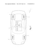
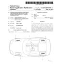
[0007] FIG. 1 schematically shows a vehicle equipped with a measuring unit for measuring the necessary physical quantities for subsequently estimating the forces that act on the tyres;
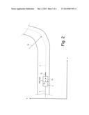
[0008] FIG. 2 schematically shows a section of a sample road route followed by the vehicle of FIG. 1; and
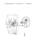
[0009] FIG. 3 schematically shows a test bench that subjects a tyre to an indoor endurance test; and
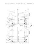
[0010] FIG. 4 is a diagram that schematically shows some of the mathematical transformations that are performed during an optimization process that increases the overall efficiency of the indoor bench test.
PREFERRED EMBODIMENTS OF THE INVENTION
[0011] In FIG. 1, reference numeral 1 indicates, in its entirety, a vehicle equipped with four tyres 2.
[0012] The vehicle 1 is equipment with a measuring unit 3 for measuring the necessary physical quantities for subsequently estimating the forces that act on the tyres 2. Thanks to the information recorded by the measuring unit 3, it is possible the determine the stress (forces) that should be applied to a tyre during an indoor endurance bench test to simulate with high accuracy a similar outdoor endurance test carried out on roads open to vehicular traffic. In other words, by processing the information recorded by the measuring unit 3, as described further on, it is possible to determine the course over time of the stress (forces) that should be applied to a tyre during an indoor endurance bench test to subject the tyre to the same wear that would take place in a similar outdoor endurance test carried out on roads open to vehicular traffic.
[0013] The measuring unit 3 comprises a satellite positioning device 4, which measures the longitudinal speed Vx of forward movement of the vehicle 1 and the position P of the vehicle 1 in real time using the GPS standard. The position P of the vehicle 1 is defined by three coordinates X,Y,Z of a three-dimensional reference system having three mutually perpendicular axes; the X and Y coordinates correspond to latitude and longitude and define a plane, whilst the Z coordinate provides an altitude with respect to a reference plane (typically sea level).
[0014] In addition, the measuring unit 3 comprises a camera 5 that is arranged inside the vehicle to capture the road in front of the vehicle 1 (for example, the camera 5 could be placed facing the windscreen of the vehicle 1).
[0015] Lastly, the measuring unit 3 comprises a mass storage device 6 (consisting of a hard disk and/or RAM memory) capable of storing the data supplied by the satellite positioning device 4 and the camera 5, and a processing device 7 that is typically constituted by a personal computer, which could internally integrate the storage device 6.
[0016] The method used for determining the stress (forces) that should be applied to a tyre during an indoor endurance bench test to simulate with high accuracy a similar outdoor endurance test carried out on roads open to vehicular traffic, will now be described.
[0017] The vehicle 1 equipped with the measuring unit 3 is used to carry out the outdoor test that it is wished to simulate indoors and is consequently driven along a sample road route where testing is carried out outdoors on roads open to vehicular traffic.
[0018] The mass M of the vehicle 1 is determined beforehand, i.e. before starting the road test; according to one possible embodiment, the mass M of the vehicle 1 can be progressively updated (i.e. reduced) to take into account the reduction due to fuel consumption (which is easy to estimate from information provided by an electronic engine control unit).
[0019] While the vehicle 1 is being driven, the satellite positioning device 4 provides, in real time and with a relatively high sampling frequency (typically, at least several Hz), the position P of the vehicle 1 along the sample road route, constituted by the X,Y,Z set of coordinates, and the longitudinal speed V, of forward movement of the vehicle 1; this data is cyclically stored in the storage device 6 with a storage frequency of that is usually equal to the sampling frequency of the satellite positioning device 4 and is synchronized with the sampling frequency of the satellite positioning device 4.
[0020] In addition, while the vehicle 1 is being driven, the camera 5 provides images of the road in front of the vehicle 1 in real time; at least a part of these images is cyclically stored in the storage device 6 with a storage frequency that is usually equal to the sampling frequency of the satellite positioning device 4 and is synchronized with the sampling frequency of the satellite positioning device 4 (in this way, each stored image is associated with the corresponding position P of the vehicle 1 at the time when the image was taken).
[0021] Once the outdoor test terminates (or rather once the journey along the sample road route is completed), the information stored by the measuring unit 3 whilst travelling along the sample road route is processed to determine the stress (forces) that should be applied to a tyre during an indoor endurance bench test to simulate the outdoor endurance test with high accuracy.
[0022] According to a preferred embodiment, moving average filters are applied to the measurements supplied by the satellite positioning device 4 (in particular, to the longitudinal speed Vx of forward movement of the vehicle 1) to eliminate any high frequency noise (very bothersome, especially in a time differentiation).
[0023] Using the longitudinal speed Vx data of forward movement of the vehicle 1, the processing device 7 calculates a longitudinal acceleration Ax of the vehicle 1 by determining the rate of change (first time derivative) of the longitudinal speed Vx of forward movement of the vehicle 1.
[0024] In addition, using the position P data of the vehicle 1 stored in the storage device 6, the processing device 7 determines a trajectory T of the vehicle 1 in the plane defined by the two coordinates X and Y (corresponding to latitude and longitude); in other words, the trajectory T of the vehicle 1 is given by the evolution of the position P of the vehicle 1 in the plane defined by the X and Y coordinates. Successively, the processing device 7 calculates a radius (R) of curvature of the trajectory T of the vehicle 1 through simple geometrical calculations and then calculates a lateral acceleration Ay of the vehicle 1 based on the longitudinal speed Vx of forward movement (corrected as previously described) and the radius (R) of curvature of the trajectory T through a simple mathematical operation described by the following equation:
Ay=Vx2/R
[0025] The processing device 7 calculates a longitudinal inertial force FIx acting on the vehicle 1 by multiplying the mass M of the vehicle 1 by the longitudinal acceleration Ax of the vehicle 1 and calculates a lateral inertial force FIy acting on the vehicle 1 by multiplying the mass M of the vehicle 1 by the longitudinal acceleration Ax of the vehicle 1 as described by the following equations:
FIx=M*A,
FIy=M*Ay
[0026] According to a preferred embodiment, the processing device 7 determines an altitude of the vehicle 1 based on the third coordinate Z, determines the gradient of the road on which the vehicle 1 travels based on the evolution of the altitude of the vehicle 1 through simple geometrical calculations and, lastly, determines a gravitational force FG acting on the vehicle 1 based on the gradient of the road on which the vehicle 1 travels through simple geometrical calculations. In other words, the gravitational force FG acting on the vehicle 1 is calculated by multiplying the overall weight force acting on the vehicle 1 (equal to mass M multiplied by gravitational acceleration G) by the sine of the gradient angle of the road on which the vehicle 1 travels.
[0027] According to a preferred embodiment, the processing device 7 also determines an aerodynamic force FA acting on the vehicle 1 as a function of the longitudinal speed Vx of forward movement of the vehicle 1; the aerodynamic force FA can be calculated by using a theoretically-determined equation having experimentally-determined parameters, or can be calculated using an experimentally-determined table (typically using interpolation between the points of the table).
[0028] Finally, the processing device 7 determines the overall longitudinal force Fx acting on the vehicle 1 by algebraically adding (i.e. taking positive and negative signs into account) the longitudinal inertial force FIx (having a positive or negative sign corresponding to a deceleration or an acceleration), the gravitational force FG (having a positive or negative sign corresponding to a descent or a rise) and the aerodynamic force FA (always having a negative sign), as described by the following equation:
Fx=FIx+FG+FA
[0029] Instead, the overall lateral force. Fy acting on the vehicle 1 is assumed to be equal to the lateral inertial force FIy, i.e. contributions other than the lateral inertial force FIy are not contemplated.
[0030] The overall forces Fx and Fy acting on the vehicle 1 are divided between the tyres 2, i.e. a partial quota of the overall forces Fx and Fy acting on the vehicle 1 is determined for each tyre 2, based on the geometrical characteristics of the vehicle 1 (i.e. the distribution of masses in the vehicle 1) and the types of suspension on the vehicle 1.
[0031] At the end of the above-described operations, the time evolution of the longitudinal speed Vx, the time evolution of the longitudinal force Fx and the time evolution of the lateral force Fy have been calculated; these time evolutions can be used directly to pilot the actuators of the test bench to simulate the outdoor endurance test with high accuracy.
[0032] In accordance with the present invention, the time evolution of the longitudinal speed Vx, the time evolution of the longitudinal force Fx and the time evolution of the lateral force Fy are subjected to an optimization process so as to increase the overall efficiency of the indoor bench test, while at the same time maintaining high simulation accuracy with regard to the outdoor endurance test.
[0033] The optimization process transforms the longitudinal speed Vx and the forces Fx and Fy from the time domain t (i.e., functions of time t) to the space domain s (i.e., functions of space s), consequently obtaining the longitudinal speed V, and the forces Fx and Fy. Since the longitudinal speed Vx is known, this transformation is simple and rapid, as the relation existing between space s and time (i.e., ds=dvdt) is determined immediately:
s ( T ) = ∫ 0 T V x ( t ) t ##EQU00001##
[0034] In other words, the longitudinal speed Vx(s) and the forces Fx(s) and Fy(s) are obtained from the longitudinal speed Vx(t) and the forces Fx(t) and Fy(t).
[0035] Once the longitudinal speed Vx and the forces Fx and Fy are transformed from the time domain t to the space domain s (i.e. after passing from Vx(t), Fx(t) and Fy(t) to Vx(s), Fx(s) and Fy(s)), the longitudinal speed Vx is dilated by applying a multiplication factor k (greater than one) and the space s is dilated by applying a multiplication factor k2 (greater than one) that is obviously greater than multiplication factor k. In other words, both the longitudinal speed Vx and the space s are dilated (increased) by corresponding multiplication factors k and k2 and space s is dilated more than longitudinal speed Vx. In general, the multiplication factor k is between 1.2 and 2.5 and so the multiplication factor k2 is between 1.44 and 6.25 (respectively corresponding to 1.22 and 2.52). The dilated (by multiplication factor k) longitudinal speed Vx and the forces Fx and Fy in the space domain s are resampled with respect to the dilated (by multiplication factor k2) space s.
[0036] Once the resampling of the dilated longitudinal speed V, and the forces Fx and Fy with respect to the dilated space s is performed, the resampled longitudinal speed Vx and the resampled forces Fx and Fy are retransformed from the space domain s (i.e., functions of space s) to the time domain t (i.e., functions of time t). This subsequent transformation for returning to the time domain t is necessary because the actuators of the test bench must be piloted according to time t. It is important to note that this further transformation is simple and rapid as the relation between space s and time t is provided directly by the longitudinal speed Vx, as previously described.
[0037] Summarizing, the following operations are performed:
Vx(t), Fx(t), Fy(t)=>Vx(s), Fx(s), Fy(s) 1.
Vx(s), Fx(s), Fy(s)=>Vx(sk2)k, Fx(sk2), Fy(sk2) 2.
Vx(sk2)k, Fx(sk2), Fy(sk2)=>Vx(t), Fx(t), Fy(t) 3.
[0038] According to a more general embodiment, once the longitudinal speed Vx and the forces Fx and Fy are transformed from the time domain t to the space domain s, the longitudinal speed Vx is dilated by applying a multiplication factor kv (greater than one) and the space s is dilated by applying a multiplication factor ks (greater than one) that is larger than multiplication factor kv, but is not necessarily the square of multiplication factor ks. In other words, both the longitudinal speed Vx and the space s are dilated (increased) by corresponding multiplication factors kv and ks and the space s is dilated more than the longitudinal speed Vx (in any case, multiplication factor ks is equal to or greater than the square of multiplication factor kv). According to a possible embodiment, multiplication factor ks is dependent on multiplication factor kv and, in particular, multiplication factor ks is a power n (with n greater or equal to 2) of multiplication factor kv (i.e., ks=kvn) ; according to other embodiments, a different mathematical association could exist between the two multiplication factors kv and ks, or there might not be any mathematical association between the two multiplication factors kv and ks, as long as the condition ks>kv2 is respected.
[0039] FIG. 4 schematically shows some of the mathematical transformations that are performed during the optimization process: the two graphs on the left show the evolution of the longitudinal speed Vx and the longitudinal force Fx as functions of space s (i.e., in the space domain) while the two graphs on the right show the evolution of the longitudinal speed Vx and the longitudinal force Fx as functions of time t (i.e., in the time domain).
[0040] For a better understanding of the optimization process, a simple numerical example is given below. It is assumed that the vehicle is driven at 40 km/h along a straight route 10 km long and that the driver alternately steers to the right and the left (in substance, a slalom or zigzag around the rectilinear trajectory) a 100 times (therefore every 100 metres, or every 9 seconds) imposing wear energy on each tyre 2 equal to 10,000 Nkm and an wear energy density of 1,000 N (10,000Nkm/10Km); in these conditions:
[0041] duration of the test is 15 minutes (10 km/40 km/h);
[0042] efficiency is 0.66 km/min (10 km/15 min);
[0043] overall wear energy received by each tyre 2 is 10,000 NKm;
[0044] wear energy density is 1,000 N.
[0045] If the speed is extended by multiplication factor kv equal to 1.5 and the space is extended by multiplication factor ks equal to 2.25 (i.e., 1.52), then:
[0046] the driver must alternately steer to the right and the left every 225 metres (1002.25) or every 13.5 seconds;
[0047] overall length becomes 22.5 Km;
[0048] duration of the test becomes 22.5 minutes (22.5 km/60 km/h);
[0049] efficiency becomes 1 km/min (22.5 km/22.5 min);
[0050] overall wear energy received by each tyre 2 becomes 22,500 NKm (1000N22.5 Km);
[0051] wear energy density remains unchanged at 1,000 N.
[0052] On comparing the two situations, it appears evident that the second situation is more efficient (1 km/min against 0.66 km/min) even though it has a lower stress level imparted by the driver (or rather, by the actuators of the test bench), as instead of swerving every 9 seconds, swerving must be every 13.5 seconds.
[0053] The above-described optimization process enables test efficiency to be significantly increased; in particular, the main quantity used for evaluating test efficiency is the average speed (i.e., the mean ratio between space and time), which is increased by an amount equal to multiplication factor kv.
[0054] In addition, the above-described optimization process has a positive effect on the rapidity with which the stresses applied to the tyre under test are varied (to avoid exceeding the test bench's limits and thus render the test unworkable, it is important that the rapidity with which the stresses applied to the tyre under test are varied is not too high).
[0055] One quantity used for assessing the rapidity with which the stresses applied to the tyre under test are varied is the "speed rate", which is equal to the longitudinal acceleration (i.e., the first time derivative of the longitudinal speed Vx); this rate varies by an amount equal to the ratio between the square of multiplication factor kv (kv2) and multiplication factor ks (i.e., by an amount equal to kv2-n when ks=kyn and therefore by an amount equal to 1 when ks=kv2). A further quantity used to assess the speed of the stresses applied to the tyre under test is the "input rate", which is equal to the first time derivative of the forces Fx and Fy; this rate varies by an amount equal to the ratio between multiplication factor kv and multiplication factor ks (i.e., by an amount equal to kv1-n when ks=kvn and therefore by an amount equal to kv-1 when ks=kv2)
[0056] The above-described optimization process is based on the assumption (amply verified, as long as the longitudinal speed Vx does not become too high) that tyre wear depends on the number of revolutions performed by the tyre independently (or rather, almost independently) of the speed with which the tyre turns. In reality, speed has a minimum impact on wear, but is has been observed that in a first approximation, the wear effect due to changes in speed can be ignored (at least as long as the longitudinal speed Vx does not become too high).
[0057] The above-described method for determining the stress that should be applied to a tyre during an indoor endurance bench test has numerous advantages.
[0058] First of all, the above-described method is of simple and inexpensive implementation, as the use of a single measuring instrument (the satellite positioning device 4) that is relatively inexpensive, easy to install and does not require any presetting, is contemplated.
[0059] The above-described method is extremely precise and, above all, is in no way affected by time drifts, as the satellite positioning device 4 has low noise levels, provides high precision and is not affected by time drifts (either due to component aging or thermal effects) as, unlike an accelerometer, it has no sensitive elements physically involved in taking measurements.
[0060] The satellite positioning device 4 is in no way affected by movements of the body of the vehicle 1 and therefore the measurements provided by the satellite positioning device 4 are not influenced by movements of the body of the vehicle 1 on the suspension.
[0061] Thanks to the information provided by the satellite positioning device 4 on the altitude of the vehicle 1, it is also possible to determine the gravitational force FG acting on the vehicle 1 with precision, based on the gradient of the road on which the vehicle 1 is travelling.
[0062] Finally, thanks to the above-described optimization process, it is possible to significantly increase the efficiency of indoor bench testing without having a negative effect on the rapidity with which stress is applied to the tyre under test.
User Contributions:
Comment about this patent or add new information about this topic:
Images included with this patent application:
 |  |
 |  |
 |
| New patent applications in this class: | |
| Date | Title |
|---|---|
| 2019-05-16 | Driverless transportation system |
| 2019-05-16 | Real time streaming analytics for flight data processing |
| 2018-01-25 | Diagnostic testing of rapid heat up of an exhaust sytem during engine decompression |
| 2017-08-17 | System and method for monitoring mining machine efficiency |
| 2017-08-17 | Aircraft weight and balance tool system |
| Top Inventors for class "Data processing: vehicles, navigation, and relative location" | |
| Rank | Inventor's name |
|---|---|
| 1 | Anthony H. Heap |
| 2 | Ajith Kuttannair Kumar |
| 3 | Christopher P. Ricci |
| 4 | Roderick A. Hyde |
| 5 | Lowell L. Wood, Jr. |