Patent application title: DEFLECTION MIRROR ARRANGEMENT FOR AN OPTICAL MEASUREMENT APPARATUS AND CORRESPONDING OPTICAL MEASUREMENT APPARATUS
Inventors:
Heiner Bayha (Satow, DE)
Peter Horvath (Freudental, DE)
Thomas Schuler (Wiernsheim, DE)
Assignees:
VALEO SCHALTER UND SENSOREN GMBH
IPC8 Class: AG02B2610FI
USPC Class:
3592007
Class name: Using a periodically moving element with particular mount or driver for element electromagnetic driver
Publication date: 2014-01-30
Patent application number: 20140029075
Abstract:
The invention relates to a deflection mirror arrangement (30) for an
optical measurement apparatus having at least one mirror unit (31, 32),
which is arranged on a rotatable shaft (34) and comprises at least one
deflection mirror (31.1, 31.2, 32.1, 32.2), and having a drive unit (33),
which drives the rotatable shaft (34), and to an optical measurement
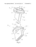
apparatus having such a deflection mirror arrangement (30).
In order to enable a reduction in the necessary installation space, the
at least one mirror unit (31, 32) comprises at least two deflection
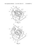
mirrors (31.1, 31.2, 32.1, 32.2), which are arranged in a common
horizontal plane such that they are radially spaced apart with respect to
the rotatable shaft (34), with the drive unit (33) being arranged at
least partially in the space between the two deflection mirrors (31.1,
31.2).Claims:
1. A deflection mirror arrangement for an optical measurement apparatus
having at least one mirror unit, which is arranged on a rotatable shaft
and comprises: at least two deflection mirrors; and a drive unit, which
drives the rotatable shaft, wherein the at least two deflection mirrors
are arranged in a common horizontal plane such that they are radially
spaced apart with respect to the rotatable shaft, with the drive unit
being arranged at least partially in the space between the two deflection
mirrors.
2. The arrangement according to claim 1, wherein the at least two deflection mirrors are arranged on a carrier plate, with the drive unit being arranged in a hole (35.1) in the carrier plate (35).
3. The arrangement according to claim 2, wherein a collar is formed at the edge of the hole in the carrier plate.
4. The arrangement according to claim 1, wherein the at least one mirror unit is configured as one selected from the group consisting of a transmitting mirror unit having at least two transmitting deflection mirrors and a receiving mirror unit having at least two receiving deflection mirrors.
5. The arrangement according to claim 4, wherein a transmitting mirror unit having two transmitting deflection mirrors, which are arranged on the carrier plate having a hole such that they are radially spaced apart, and a receiving mirror unit having two receiving deflection mirrors are arranged on the common rotatable shaft such that they are axially spaced apart from one another, with the drive unit being arranged in the space between the two transmitting deflection mirrors.
6. The arrangement according to claim 5, wherein the receiving deflection mirrors are secured in each case on a side of a carrier body such that they are radially spaced apart.
7. The arrangement according to claim 6, wherein an encoding disc capable of being evaluated to determine the rotational angle of the rotatable shaft, is arranged between the transmitting mirror unit and the receiving mirror unit below the carrier plate.
8. The arrangement according to claim 1, wherein the drive unit is configured as a stepper motor.
9. The arrangement according to claim 1, wherein the rotatable shaft is mounted on both sides.
10. An optical measurement apparatus, comprising: at least one optical transmitter; at least one optical receiver; and a deflection mirror arrangement having at least one mirror unit, which is arranged on a rotatable shaft and comprises at least one deflection mirror, and having a drive unit, which drives the rotatable shaft, wherein the deflection mirror arrangement is configured according to claim 1.
Description:
[0001] The invention relates to a deflection mirror arrangement for an
optical measurement apparatus of the type mentioned in the preamble of
Claim 1 and to a corresponding optical measurement apparatus having such
a deflection mirror arrangement.
[0002] Scanning optical measurement apparatuses, referred to as laser scanners, which determine the distance from objects or obstacles detected in the monitoring region according to the light-pulse time-of-flight method, for vehicles for detecting objects or obstacles in a monitoring region are known from the prior art.
[0003] Patent specification DE 10 2005 055 572 B4 for example describes a scanning optical distance sensor. The distance sensor described comprises at least one laser as an optical transmitter, at least one detector as an optical receiver, and a deflection unit, which deflects generated laser radiation onto the scene to be measured using a first mirror, and deflects the laser pulses that are scattered back by objects onto the at least one detector using a second mirror. Here, the first and second mirrors are arranged on a common rotatable shaft, which is driven by a drive unit. The first mirror is arranged on a first holder and the second mirror is arranged on a second holder with an axial spacing from the first mirror, with the drive unit being arranged between the two holders. The at least one laser and the at least one detector with the associated electronics are arranged in an upright manner.
[0004] It is the object of the invention to develop a deflection mirror arrangement for an optical measurement apparatus of the type mentioned in the preamble of Claim 1 such that it becomes possible to reduce the necessary installation space, and to specify a corresponding optical measurement apparatus.
[0005] This object is achieved according to the invention by a deflection mirror arrangement for a laser scanner having the features of Claim 1 and by an optical measurement apparatus having the features of Claim 10. Further features which advantageously realize the embodiments of the invention are contained in the dependent claims.
[0006] The advantage achieved by the invention is that, owing to the fact that the drive unit is arranged in the space between the two deflection mirrors, the necessary installation space for the deflection mirror arrangement can be reduced. Thus, in particular the installation height of the deflection mirror arrangement can be reduced.
[0007] The fundamental idea of the invention is based on the realization of a mirror unit having two mirrors which are arranged spaced apart with respect to one another in a horizontal plane, and between which the drive unit is then arranged. Furthermore, mounting the mirror unit on both sides can be realized more easily by arranging the mirrors on a carrier plate or on a carrier body.
[0008] A deflection mirror arrangement according to the invention for an optical measurement apparatus comprises at least one mirror unit, which is arranged on a rotatable shaft and comprises at least one deflection mirror, and a drive unit, which drives the rotatable shaft. According to the invention, the at least one mirror unit comprises at least two deflection mirrors, which are arranged with a radial spacing from the rotatable shaft, with the drive unit being arranged at least partially in the space between the two deflection mirrors.
[0009] In one advantageous configuration of the arrangement according to the invention, the at least two deflection mirrors are arranged on a carrier plate, with the drive unit being arranged in a hole in the carrier plate. Thereby the two-sided mounting of the mirror unit can be realized more easily and deviations in the rotation movement can be reduced. In order to simplify the arrangement of the drive unit in the hole in the carrier plate, a circumferential collar can be formed at the edge of the hole.
[0010] The at least one mirror unit can be configured for example as a transmitting mirror unit having at least two transmitting deflection mirrors and/or as a receiving mirror unit having at least two receiving deflection mirrors.
[0011] In a further advantageous configuration of the arrangement according to the invention, a transmitting mirror unit having two transmitting deflection mirrors, which are arranged on the carrier plate having a hole such that they are radially spaced apart, and a receiving mirror unit having two receiving deflection mirrors are arranged on the common rotatable shaft such that they are axially spaced apart from one another, with the drive unit being arranged in the space between the two transmitting deflection mirrors. The two receiving deflection mirrors can be secured in each case on a side of a carrier body such that they are radially spaced apart. As a result, the two-sided mounting of the receiving mirror unit can be realized more easily and deviations in the rotational movement of the receiving mirror unit can be reduced. In order to sense a current rotational angle, an encoding disc can be arranged between the transmitting mirror unit and the receiving mirror unit below the carrier plate, which encoding disc can be evaluated to determine the rotational angle of the rotatable shaft.
[0012] In a further advantageous configuration of the arrangement according to the invention, the drive unit is configured as a stepper motor. In addition, the rotatable shaft can be mounted on both sides in order to avoid swaying movements and deviations.
[0013] The deflection mirror arrangement according to the invention can preferably be used in an optical measurement apparatus having at least one optical transmitter and at least one optical receiver.
[0014] Exemplary embodiments of the invention will be explained below in more detail with reference to a drawing, in which:
[0015] FIG. 1 shows a perspective illustration of an exemplary embodiment of an optical measurement apparatus according to the invention.
[0016] FIG. 2 shows a perspective detail illustration of the optical measurement apparatus from FIG. 1, without housing.
[0017] FIG. 3 shows a perspective detail illustration of the optical measurement apparatus from FIG. 1, without drive holder.
[0018] FIG. 4 shows a perspective detail illustration of the optical measurement apparatus from FIG. 1, without transmitter unit and without drive unit.
[0019] FIG. 5 shows a perspective illustration of an exemplary embodiment of a deflection mirror arrangement according to the invention for the optical measurement apparatus from FIG. 1.
[0020] FIG. 6 shows a further perspective illustration of the exemplary embodiment of the deflection mirror arrangement according to the invention according to FIG. 5 from another observation angle.
[0021] As shown in FIG. 1, an optical measurement apparatus 1 comprises a housing 2 having a bottom plate 5. Introduced into the housing are a transmitting window 7, through which for example pulsed laser light is emitted, and a receiving window 9, through which laser light reflected by objects in a monitoring region is received.
[0022] As shown in FIGS. 2 to 4, a transmitter unit 10, a receiver unit 20 and a deflection mirror arrangement 30 are arranged inside the housing 3. The transmitter unit 10 comprises a transmitter circuit board 12, on which for example an optical transmitter 14, which is configured as a pulsed laser, with a transmission optical unit 16 is arranged. The transmitter circuit board 12 in the illustrated exemplary embodiment is mounted on a circuit carrier 18. The receiver unit 20 comprises a receiver circuit board 22, on which for example an optical receiver 24 configured as a detector is arranged, and a receiving optical unit 26, which is configured for example as a parabolic mirror.
[0023] As is shown in FIGS. 2 to 6, the deflection mirror arrangement 30 in the illustrated exemplary embodiment comprises a transmitting mirror unit 31 having two transmitting deflection mirrors 31.1, 31.2, which are arranged on a carrier plate 35 in a common horizontal plane such that they are radially spaced apart, and a receiving mirror unit 32 having two receiving deflection mirrors 32.1, 32.2, which are secured in each case on a side of a carrier body 38 such that they are radially spaced apart. As is further shown in FIGS. 2 to 6, the transmitting mirror unit 31 and the receiving mirror unit 32 are arranged on a common rotatable shaft 34 such that they are axially spaced apart with respect to one another.
[0024] According to the invention, a drive unit 33, which drives the rotatable shaft 34, is arranged substantially in the space between the two transmitting deflection mirrors 31.1, 31.2. In the illustrated exemplary embodiment, the drive unit 33 is arranged in a hole 35.1 in the carrier plate 35. A collar is formed at the edge of the hole 35.1 in the carrier plate 35 in order to simplify accommodation of the drive unit 33. The drive unit 33 is held by a holder 36, which is configured as a cover. In the illustrated exemplary embodiment, the drive unit 33 is configured as a stepper motor. Alternatively, other suitable motors and drives known to the person skilled in the art can be used for driving the rotatable shaft 34.
[0025] Arranged between the transmitting mirror unit 31 and the receiving mirror unit 32 below the carrier plate 35 is an encoding disc 37, which is evaluated to determine the rotational angle of the rotatable shaft 34. In order to evaluate the encoding disc 37, corresponding transducers or sensors can be arranged on the circuit carrier 18. Furthermore, the rotatable shaft 34 is mounted on both sides. At the upper end, the rotatable shaft 34 is mounted in the drive unit 33 and at the lower end it is mounted in a mount 39 which is introduceable into the bottom plate 5.
[0026] The result for the optical measurement apparatus is thus the mode of operation described below. The fixed optical transmitter 14 generates pulsed laser beams, which are deflected via the rotating transmitting mirror unit 31 and are radiated into the region to be monitored through the transmitting window 7. Pulsed laser beams are received via the receiving window 9, which laser beams are reflected by objects or obstacles, which are arranged in the monitoring region, in response to the emitted pulsed laser beams. The received laser beams are deflected via the receiving mirror unit 32 and are guided from the fixed receiving optical unit 26 to the fixed optical receiver 24. The output signal of the optical receiver 14 is evaluated to ascertain the time of flight of the laser beams in order to ascertain the distance from an object detected in the monitoring region.
[0027] The fundamental idea of the invention can also be used in a non-illustrated deflection mirror arrangement, which has a transmitting mirror unit and a receiving mirror unit which are not arranged on a common rotary shaft, but each have a dedicated drive unit. In such an embodiment, the drive unit for the transmitting mirror unit is arranged, as in the illustrated exemplary embodiment, substantially in the space between the two transmitting deflection mirrors, which are arranged in a common horizontal plane such that they are radially spaced apart with respect to the rotatable shaft. Furthermore, the drive unit for the receiving mirror unit is arranged substantially in the space between the two receiving deflection mirrors, which are arranged in a common horizontal plane such that they are radially spaced apart with respect to the rotatable shaft.
User Contributions:
Comment about this patent or add new information about this topic:
Images included with this patent application:
 |  |
 |  |
| Similar patent applications: | |
| Date | Title |
|---|---|
| 2014-03-27 | Scanning optical apparatus |
| 2014-03-27 | Electrochromic panel and control device |
| 2014-03-27 | Metasurface nanoantennas for light processing |
| 2011-03-24 | Measurement apparatus |
| 2014-03-20 | Image capturing lens assembly |
| New patent applications in this class: | |
| Date | Title |
|---|---|
| 2022-05-05 | Galvanometer motor apparatus |
| 2016-04-28 | Piezoelectric and electromagnetic type two-dimensional optical deflector and its manufacturing method |
| 2016-03-17 | Scanner device |
| 2015-04-02 | Mirror rotating apparatus |
| 2014-10-23 | Mems device with multi-segment flexures |
| New patent applications from these inventors: | |
| Date | Title |
|---|---|
| 2016-01-28 | Collision protection device for a pivotable hatch of a motor vehicle, hatch, motor vehicle and corresponding method |
| 2014-11-06 | Optical measuring apparatus for a vehicle, driver assistance device having such a measuring apparatus, and vehicle having a corresponding measuring apparatus |
| 2014-02-13 | Method for operating a vehicle and driver assistance device |
| Top Inventors for class "Optical: systems and elements" | |
| Rank | Inventor's name |
|---|---|
| 1 | Tsung Han Tsai |
| 2 | Hsin Hsuan Huang |
| 3 | Michio Cho |
| 4 | Niall R. Lynam |
| 5 | Tsung-Han Tsai |