Patent application title: Wireless Remote Aiming Systems
Inventors:
Enrique Castejon, Sr. (Joliet, IL, US)
IPC8 Class: AF41G135FI
USPC Class:
42117
Class name: Sight devices focused beam (e.g., laser on target, etc.) activated by a switch
Publication date: 2014-01-09
Patent application number: 20140007485
Abstract:
Wireless remote aiming systems mounted on a weapon: Comprising of an rf
transmitter at least three switches mounted the handgrip pcb. The
transmitter signal to The receiver activates one or more of at least two
lasers and/or the led light source depending on the signal that was sent
to the receiver. At least one of the lasers mounted within the enclosure
housing is an it laser and the other maybe a red, green or blue in color
laser. The rf transmitter and/or the receiver have a build in
encoder/decoder with an rf frequency hopper. two or more of the wireless
remote aiming systems will not be in the same frequency at the same time
and interference.Claims:
1. A wireless remote aiming systems comprising: A transmitter signaling
device mounted within handgrip with at least 3 push buttons on a pcb of
flex circuit, pyralux pcb, Kapton copper clad pcb for a firearm/weapon, a
receiver signaling device comprising; of an enclosure housing mounted on
the firearm/weapon made of carbon fiber, abs plastic, aircraft aluminum
or plastic with a weaver/picatinny rail clamp that may have an external
antenna and with at least one locking connectors outputs. At least two
lasers diode, one an IR and one of visible beam, in red, green or blue.
LED light source and 3 to 6v dc battery as the power source. The
enclosure housing will have a weaver/picatinny rails clamp to mount onto
the firearm/weapon. An adapter unit with a receiver signaling device
comprising; of enclosure housing, weaver/picatinny rails clamp, and the
adapter made from aircraft aluminum, abs plastic, carbon fiber or plastic
with at least two locking output connectors and the receiver electronics,
may also have an external antenna. The flashlight comprising; of a remote
motorized focus beam and a flashlight mounting, and weaver/picatinny
rails clamping mount, motor flashlight body, end cap with connector front
lens cover and screw on cap. The transmitter and receiver communicate
thru 128 bits AES encryption and aux cord with multi size connectors to
use with other lasers and flashlights devices.
2. As to claim #1; a wireless remote aiming systems in a handgrip with transmitter signaling device and at least three momentary push button switches and a soft switch cover with finger grooves.
3. As to claim #2; a handgrip with transmitter signaling device with a 128 bit encoder/decoder within the transmitter and transmitting a wireless signal to a remotely located receiver. 3a; wherein the handgrip has at least 3 momentary push buttons mounted on pcb and mounted onto the handgrip to control any and all outputs within the enclosure housing. 3b; where the transmitter has a 3v button battery to power the handgrip transmitter with a glide in battery holder to remove the battery from its contacts.
1. As to claim #3; wherein the remotely located receiver and the enclosure housing will operated the laser and/or the led light source by the signal it receives form the handgrip transmitter.
2. As to claim #4; wherein the handgrip has a pcb mounted onto the front of the handgrip with at least three switches on the pcb and a soft cover with finger grooves on the covers.
6. As to claim #5; the handgrip has a location for the mounting of the transmitter pcb with a connector to connect the switch pcb to the transmitter pcb. Also the handgrip has a cover for the bottom of the handgrips.
7. As to claim #1; wherein the pcb for the front mounted switches may have a connector on both ends of the connector circuit to connect to the transmitter pcb and switches pcb.
8. As to claim #1; the wireless remote aiming systems #1; wherein the enclosure housing with output and antenna, receiver pcb, laser mounting housing, adjusting screws for both windage and elevation and the led lighting source are all a complete unit.
9. As to claim #8; wherein the enclosure housing may be made of aircraft aluminum, carbon fiber, abs plastics or plastics and has the receiver pcb, laser diode housing, laser diode, power supply, led light source and the output connector within the housing.
10. As to claim #9; the enclosure housing will also have the windage and elevator adjustment screws on the enclosure housing.
11. As to claim #10; wherein the enclosure housing has the mounting base with clamp for mounting onto the firearm/weapon weaver/picatinny rail.
12. As to claim #1; an adapter unit with at least two aux outputs for the connection of aux lasers and flashlights that has the locking connection cord in claim #1.
13. As to claim #12; wherein the adapter unit has the receiver pcb within the enclosure housing and the 3-6v dc power supply and at least two locking connector outputs.
14. As to claim #13; wherein the adaptor unit may be made of aircraft aluminum, carbon fiber, abs plastic or plastic.
15. As to claim #14; wherein the adaptor unit can be used to control other models of lasers and flashlights with the use of the locking connection cord in claim #1.
16. As to claim #15; the adaptor unit has a weaver/picatinny rail base clamp to mount onto a firearm/weapon.
17. As to claim #16; wherein the adaptor unit will receive the signal from the handgrip transmitter for controlling one or more of the at least two outputs.
18. As to claim #1; a remote focus flashlight that is motorized and can be controlled by the handgrip transmitter.
19. As to claim #18; wherein the remote focus flashlight has a motor, gears and shafts to focus the flashlight led light source from a beam to a flood.
20. As to claim #19; wherein the remote focus flashlight is made from aircraft aluminum.
21. As to claim #1; a multi sizes connector's cord which can be used to control other control other lasers and/or flashlights.
22. As to claim #1; both of the enclosure housing and the adaptors enclosure housing mounts are made of a combination of aircraft aluminum and/or carbon fiber or ABS plastics.
Description:
BACKGROUND OF INVENTIONS
Field of Invention
[0001] The invention pertains generally to the wireless remote aiming systems and practically to their use with the firearms/weapons.
[0002] Firearms have many types of aiming devices and light sources: for example iron sights, scopes and lasers. Some light sources come in many configurations and sizes, some with led, incandescent and/or xenon light source. These lasers and lighting devices, all have a few things in common. They all have a pressure switch within the plastic and/or a small push button on the end caps of the device to power them on. These types of devices make it difficult to maintain control of the firearm/weapon. The devices mentioned above are all in use by law enforcement, military and civilians alike today. The use of the pressure switch and/or the end cap button switches simultaneously makes holding the firearm/weapons difficult and unstable.
[0003] A new innovation in targeting Technology.
[0004] These types of devices are mounted to the firearm/weapons with the use of a screw and a clamp onto the weaver/picatinny rails on the firearm/weapon. The switches that come with the devices are also mounted onto the same weaver/picatinny rails. The methods used to mount the switches onto the firearm/weapons are with two face tape, Velcro or are wire tied to the firearm/weapon. Same times a combination of two or more of the above methods have been used; to fix the switches onto the firearm/weapon has been used.
BACKGROUND OF INVENTIONS
Field of Invention
[0005] Some have also used black electrical tape with the methods mentioned above. These devices all come with a long pressure switch cord that is used to connect the pressure switch to the batteries. When using the Velcro and two faced tape on the flat plastic pressure switches they have been known to fall off. If the cord that is attached to the device gets hooked onto some thing or they work their way off over a period of time.
[0006] While lasers aiming devices have been used for targeting, it will not illuminate the targets or the surrounding area. Consequently it's both desirable and sometimes necessary to have ones firearm/weapon equipped with a laser aiming device and/or IR flashlight source or a visible flashlight lighting source.
[0007] The device has to stay powered on or the operator has to reach over to wear the device is and push the button with their thumb to have the light stay lite or turn off. When the operator no longer needs the light that was left on they have to reach over to turn it off. They have to release full control of the firearm/weapon. This action has to be repeated each time the operator needs to power on one or both of the attached devices.
[0008] These are some of the drawbacks to the current devices on the market and some are more difficult to use. Some include the use of a selector switch within its design which makes it even a more challenging task.
[0009] By incorporating the control to both the laser and/or the flashlight to the handgrip the operator can maintain full control of the firearm/weapon and also can control the mounted devices, to only when he/she needs them to be on.
THE INVENTION SUMMARY
[0010] The invention is comprised of a hand grip with a transmitter; at least 3 switches on a pcb and soft cover with finger grooves in the front of the hand grip. A receiver comprising the enclosure housing with at least two lasers and its housing mounting, of which at least one of the laser is an it laser diode and one of red, green or blue laser diode with adjusting for both the elevation and windage. With a led light source and it may have an antenna and at least one output on the enclosure housing.
[0011] The system also has an adaptor unit comprising of at least two outputs for attaching the motorized remote focus flashlight and/or a laser with connecting cords. And a flashlight comprising of a motorized remotely focus light source into a beam or a flood light source of IR or LED visible light. All of the components are made to work as a unit; one handgrip and enclosure housing or one handgrip and adaptor with at least two outputs and the remote focus flashlight and/or a laser.
[0012] This invention is exploits in the design of the handgrip and the wireless remotes, transmitter and the receiver, by intergrading these into a unit the system has put to use the best of the system into one complete unit.
[0013] The wireless remote aiming systems will also improve targeting and lamination of the area in front of the operator of the firearm/weapon by having the control in the handgrip since the operator has his/her hand on the grip most of the times.
[0014] The invention connection cord comes in other configurations and sizes so that the operator can use some of the lasers and/or flashlights that they may have on their firearm/weapons.
THE INVENTION SUMMARY
[0015] With the use of the wireless remote aiming systems the operator can immediately take hold of his/her firearm/weapon and place the laser on the target and/or illuminate his/her target or the area around their self and not have to look for the plastic switch cover.
BRIEF DESCRIPTION OF DRAWINGS
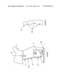
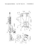
[0016] FIG. #1 is a perspective view of the handgrip #2 having the transmitter #4 pcb mounted within the handgrip opening at the bottom and switches #6, 8 and 10. The handgrip #2 bottom cover #58 and switch PCB #56.
[0017] FIG. #2 is of the front (side view) of switch cover #52 and grip switch cover with switch contact point #60.
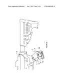
[0018] FIG. #3 is a perspective of the handgrip unit #2, on one possible type of firearm/weapon #16.
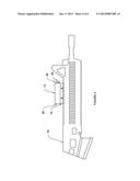
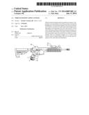
[0019] FIG. #4 is a perspective of the main aiming system unit #12, enclosure rail base #14, output connection #26, laser output #36 and Cree flashlight #40 on one possible type of firearm/weapon #16.
[0020] FIG. #5 is a perspective view of the main enclosure housing #12, main enclosure mounting #14, and handgrip #2, with switches 6, 8 and 10, transmitter #4 on one possible type of firearm/weapon #16.
[0021] FIG. #2a front view of grip switch cover #52 with switch contact points #60
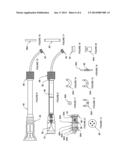
[0022] FIG. #6 Top view of the enclosure housing #12, battery power source #18, screw on battery cover #20, main unit antenna #22, receiver pcb #24, aux output #26, IR laser diode #30, windage adjustment screw #32, elevation adjustment screw #34, red--green--or blue laser diode #36, Cree led light and heat sink #38, led screw on cover #40, led reflector #42, led spring and mounting #44, receiver mounting screw #46, battery base cover #48, reflector lens #50
BRIEF DESCRIPTION OF DRAWINGS
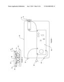
[0023] FIG. #7 wireless remote adapter apparatus #62, adapter apparatus laser connector #64, receiver pcb #66, adapter antenna #68, adapter apparatus battery base #70, adapter apparatus battery cover #72, adapter apparatus light output #76, the adapter apparatus is used for aftermarket flashlight and lasers with the use of connector #92 and #86
[0024] FIG. #8 complete motorized flashlight #84 with top cover #82, bottom cover #86 with connector #92
[0025] FIG. #9 cut away of motorized flashlight #84, flashlight reflector #80, clear lens #78, power and control flex connector #88
[0026] FIG. # 10 connectors' #86 and #92 aux connector cord
[0027] FIG. # 11 Cree led and heat sink #80a
[0028] FIG. # 12 top plate #82a
[0029] FIG. # 13 bottom plate #96
[0030] FIG. # 14 top plate shaft guild #84a
[0031] FIG. # 15 bottom shaft guild #92a
[0032] FIG. # 16 shaft #90a and gear #98
[0033] FIG. # 17 power and control flex circuit #88
[0034] FIG. #18 two vertical shafts #86a
[0035] FIG. #19 circuit connector #94
[0036] FIG. # 20 dc motor and gear #94a
[0037] FIG. #21 complete motor and all its components
[0038] FIG. #22 cut away of #16 with complete adapter apparatus and mounting
User Contributions:
Comment about this patent or add new information about this topic:
Images included with this patent application:
 |  |
 |  |
 |  |
 |
| Similar patent applications: | |
| Date | Title |
|---|---|
| 2014-05-01 | Quick detach barrel mounting system |
| 2014-05-15 | Projectile aiming optical system |
| 2014-05-08 | Visual target acquisition scope system |
| 2014-05-08 | Reticle including windage aiming points adjusted for distance to a target |
| 2014-03-13 | Firearm reticle system |
| New patent applications in this class: | |
| Date | Title |
|---|---|
| 2016-06-09 | Master module light source and trainer |
| 2015-04-30 | Realtime memorialization firearm attachment |
| 2013-07-25 | Laser aiming device |
| 2013-07-25 | Electronic firearm system |
| 2012-07-19 | Gunsight with visual range indication |
| Top Inventors for class "Firearms" | |
| Rank | Inventor's name |
|---|---|
| 1 | Michael T. Mayberry |
| 2 | Mark C. Laney |
| 3 | Stephen P. Troy |
| 4 | Russell A. Potterfield |
| 5 | Dennis Cauley |