Patent application title: Exhaust System, Operating Method And Control Strategy In Internal Combustion Engine
Inventors:
Praveen S. Chavannavar (Sholinganallur, IN)
Assignees:
Caterpillar Inc.
IPC8 Class: AF01N3023FI
USPC Class:
60274
Class name: Internal combustion engine with treatment or handling of exhaust gas methods anti-pollution
Publication date: 2013-12-12
Patent application number: 20130327017
Abstract:
An exhaust system for an internal combustion engine includes an exhaust
filter positioned within an exhaust conduit, and having a first and a
second NOx sensing mechanism positioned upstream and downstream the
exhaust filter. An electronic control unit is coupled with the NOx
sensing mechanisms and generates a signal indicative of a soot loading
state of the exhaust filter responsive to a difference in species
composition of the sensed NOx upstream and downstream the exhaust filter.
Related methodology and control strategy are also disclosed.Claims:
1. A method of operating an exhaust system for an internal combustion
engine comprising the steps of: conveying exhaust produced via operation
of the internal combustion engine in a downstream direction through an
exhaust filter of the exhaust system; trapping soot in the exhaust within
the exhaust filter; sensing NOx in the exhaust upstream the exhaust
filter; sensing NOx in the exhaust downstream the exhaust filter; and
determining a soot loading state of the exhaust filter responsive to a
difference in species composition of the sensed NOx upstream and
downstream the exhaust filter.
2. The method of claim 1 wherein the difference in species composition includes a difference in a ratio of NO to NO.sub.2.
3. The method of claim 2 wherein the step of determining includes determining the soot loading state of the exhaust filter based at least in part on an amount of NO2 deoxidized to NO within the exhaust filter as indicated by the difference in the ratio.
4. The method of claim 3 wherein: the steps of sensing include receiving data from an upstream sensing mechanism having differing sensitivity to NO versus NO2, and a downstream sensing mechanism also having the differing sensitivity; and the step of determining further includes a step of comparing the data from the upstream sensing mechanism with the data from the downstream sensing mechanism.
5. The method of claim 4 wherein the step of determining further includes determining a relative soot loading state of the exhaust filter, and further comprising a step of commanding regeneration of the exhaust filter based at least in part on the determined relative soot loading state.
6. The method of claim 3 further comprising the steps of: receiving data indicative of exhaust temperature; and receiving data indicative of exhaust flow rate; wherein the step of determining further includes determining the soot loading state responsive to the exhaust temperature and the exhaust flow rate.
7. The method of claim 3 further comprising a step of decreasing the ratio of NO to NO2 via an oxidation catalyst located upstream the exhaust filter in the exhaust system.
8. The method of claim 7 further comprising the steps of receiving data indicative of an engine-out ratio of NO to NO2, and determining the amount of NO2 deoxidized responsive to the engine-out ratio, and wherein the step of determining the soot loading state further includes a step of determining an amount of the trapped soot based on the amount of NO2 deoxidized.
9. An exhaust system for an internal combustion engine comprising: an exhaust conduit configured to couple with an exhaust manifold of the internal combustion engine; an exhaust filter positioned within the exhaust conduit and configured to trap soot in exhaust from the internal combustion engine conveyed through the exhaust conduit; a first NOx sensing mechanism configured to sense NOx in the exhaust upstream the exhaust filter; a second NOx sensing mechanism configured to sense NOx in the exhaust downstream the exhaust filter; an electronic control unit coupled with the first and second NOx sensing mechanisms, and configured to generate a signal indicative of a soot loading state of the exhaust filter responsive to a difference in species composition of the sensed NOx upstream and downstream the exhaust filter.
10. The exhaust system of claim 9 further comprising a regeneration device coupled with the exhaust filter and controllably coupled with the electronic control unit, and wherein the electronic control unit is configured to command regeneration of the exhaust filter via the regeneration device, responsive to the signal.
11. The exhaust system of claim 10 further comprising a diesel oxidation catalyst positioned within the exhaust conduit upstream the exhaust filter, and wherein the exhaust filter is free of catalyst.
12. The exhaust system of claim 11 wherein the first NOx sensing mechanism is positioned downstream the diesel oxidation catalyst.
13. The exhaust system of claim 11 wherein the first NOx sensing mechanism is positioned upstream the diesel oxidation catalyst.
14. The exhaust system of claim 10 wherein each of the first and second sensing mechanisms has differing sensitivity to NO versus NO2, and the difference in species composition includes a difference in a ratio of NO to NO2 in the exhaust.
15. The exhaust system of claim 14 wherein the signal is indicative of an amount of NO2 deoxidized to NO within the exhaust filter, and the electronic control unit is further configured to determine an amount of the trapped soot based on the amount of NO2 deoxidized.
16. The exhaust system of claim 14 wherein the electronic control unit is configured to receive data indicative of a temperature of the exhaust, and data indicative of an exhaust flow rate, and further configured to determine the amount of the trapped soot responsive to the exhaust temperature and the exhaust flow rate.
17. A control system for an exhaust filter in an internal combustion engine system comprising: a first NOx sensing mechanism configured to sense NOx in the exhaust at a first location upstream the exhaust filter in an exhaust conduit configured to connect with an exhaust manifold of the internal combustion engine; a second NOx sensing mechanism configured to sense NOx in the exhaust at a second location downstream the exhaust filter in the exhaust conduit; an electronic control unit coupled with the first and second NOx sensing mechanisms, and configured to generate a signal indicative of a soot loading state of the exhaust filter responsive to a difference in species composition of the sensed NOx upstream and downstream the exhaust filter.
18. The control system of claim 17 wherein each of the first and second NOx sensing mechanisms has differing sensitivity to NO versus NO.sub.2.
19. The control system of claim 18 further comprising an exhaust temperature monitoring mechanism, and an exhaust flow rate monitoring mechanism, and the electronic control unit is further configured to generate the signal responsive to data from the first and second NOx sensing mechanisms, and responsive to data from the exhaust temperature and exhaust flow rate monitoring mechanisms.
Description:
TECHNICAL FIELD
[0001] The present disclosure relates generally to soot detection in an exhaust filter for an internal combustion engine, and relates more particularly to determining a soot loading state of the exhaust filter responsive to a change in species composition of NOx.
BACKGROUND
[0002] A great many different types of aftertreatment systems have been used in connection with internal combustion engines for decades. In many instances, it is desirable to remove particulates in exhaust from internal combustion engines, and exhaust particulate filters or "traps" are widely used for this purpose. While many exhaust particulate filters are quite effective at trapping soot, eventually the quantity of trapped soot reaches a point at which continued operation of the engine becomes problematic or less efficient, or risks damaging the exhaust particulate filter. "Regeneration" is a term generally used to describe the process of cleansing an exhaust particulate filter of trapped soot. One typical approach involves raising the temperature within the filter to a point sufficient to combust the trapped soot and convert it into less undesirable or more readily treated emissions.
[0003] A number of different regeneration techniques are well known and widely used. Among these are the use of catalysts resident within an exhaust particulate filter or carried within the engine fuel. Catalysts can assist in combustion of soot at relatively lower temperatures than what might otherwise be required. Other regeneration techniques rely upon injection of a fuel into the exhaust gases, which subsequently ignites upstream of, or upon entering the exhaust particulate filter to increase the temperature therein. Still other techniques utilize in-cylinder dosing or dosing downstream the engine and upstream the filter, to deliver a fuel which raises filter temperature by way of an exothermic reaction without actually igniting. Electrically powered heaters and the like, unconventional engine timing and/or fueling techniques, and back-pressure generating flow restrictors are also used. Regeneration technologies utilizing catalysts tend to be quite expensive, whereas techniques employing electric heaters or specialized engine operation strategies may siphon off energy from the engine. Delivery of fuel into the exhaust gases directly consumes fuel, whereas generating back pressure can reduce the ease with which exhaust gases exit the engine. It will thus be readily apparent that most, if not all, regeneration strategies carry some sort of cost or efficiency penalty.
[0004] In many regeneration strategies it is thus desirable to detect an amount of trapped soot within the filter with relative precision and accuracy. On the one hand, it is typically desirable to avoid operating an engine system with an inordinately packed filter, while on the other hand it is desirable to avoid overuse of energy and/or reactant-consuming regeneration strategies. For these reasons, engineers are continually seeking techniques to more accurately and precisely detect an actual amount of trapped soot so that underuse and overuse of regeneration can be avoided. Even seemingly miniscule improvements in detecting soot load, and thus suitable regeneration conditions, can translate into significant real world gains in efficiency.
[0005] One general class of soot detection technologies employs electromagnetic energy transmitted through an exhaust particulate filter, and reduced in strength as a portion of the electromagnetic energy is absorbed by trapped soot. These techniques have been known for a number of years, but have yet to achieve their full theoretical potential. Certain of these strategies seek to detect soot based upon observation of phenomena such as frequency shift or other signal attributes in electromagnetic energy transmitted through trapped soot. Others have sought to link the extent of reduction in signal strength to soot amount. One example strategy for leveraging electromagnetic energy loss in response to trapped soot is taught in U.S. Pat. No. 5,497,099 to Walton. These known techniques tend to be computationally challenging, require the use of relatively expensive and complex hardware, or suffer from other shortcomings. Moreover, strategies which appear to perform acceptably in the lab are often discovered to be poorly suited to actual field conditions.
SUMMARY
[0006] In one aspect, a method of operating an exhaust system for an internal combustion engine includes conveying exhaust produced via operation of the internal combustion engine in a downstream direction through an exhaust filter of the exhaust system, and trapping soot in the exhaust within the exhaust filter. The method further includes sensing NOx in the exhaust upstream the exhaust filter, sensing NOx in the exhaust downstream the exhaust filter, and determining a soot loading state of the exhaust filter responsive to a difference in species composition of the sensed NOx upstream and downstream the exhaust filter.
[0007] In another aspect, an exhaust system for an internal combustion engine includes an exhaust conduit configured to couple with an exhaust manifold of the internal combustion engine, and an exhaust filter positioned within the exhaust conduit and configured to trap soot and exhaust from the internal combustion engine conveyed through the exhaust conduit. The system further includes a first NOx sensing mechanism configured to sense NOx in the exhaust upstream the exhaust filter, and a second NOx sensing mechanism configured to sense NOx in the exhaust downstream the exhaust filter. The system further includes an electronic control unit coupled with the first and second NOx sensing mechanisms, and configured to generate a signal indicative of a soot loading state of the exhaust filter responsive to a difference in species composition of the sensed NOx upstream and downstream the exhaust filter.
[0008] In still another aspect, a control system for an exhaust filter in an internal combustion engine system includes a first NOx sensing mechanism configured to sense NOx in the exhaust at a first location upstream the exhaust filter in an exhaust conduit configured to connect with an exhaust manifold of the internal combustion engine, and a second NOx sensing mechanism configured to sense NOx in the exhaust at a second location downstream the exhaust filter in the exhaust conduit. The control system further includes an electronic control unit coupled with the first and second NOx sensing mechanisms, and configured to generate a signal indicative of a soot loading state of the exhaust filter responsive to a difference in species composition of the sensed NOx upstream and downstream the exhaust filter.
BRIEF DESCRIPTION OF THE DRAWINGS
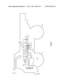
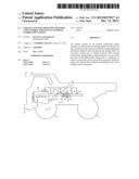
[0009] FIG. 1 is a side diagrammatic view of a machine having an exhaust system, according to one embodiment;
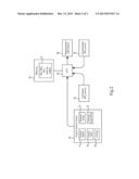
[0010] FIG. 2 is a block diagram of a control system, according to one embodiment; and
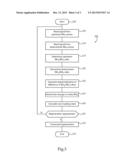
[0011] FIG. 3 is a flowchart illustrating example control methodology, according to one embodiment.
DETAILED DESCRIPTION
[0012] Referring to FIG. 1, there is shown a machine 10 having an internal combustion engine system 15, according to one embodiment. Machine 10 is shown in the context of an off-highway truck having a frame 12, and ground-engaging elements 14 coupled with frame 12. In other embodiments, machine 10 might include an on-highway machine, a track-type machine having ground-engaging tracks rather than propulsion wheels, or still another type of machine such as a motor grader, a backhoe, a wheel loader, a scraper, or even a marine vessel. Machine 10 might also include a stationary machine such as a generator, compressor or a pump. Engine system 15 may include an internal combustion engine 18 such as a compression ignition diesel engine, providing motive power to ground-engaging elements 14. Engine 16 includes an exhaust manifold 20 coupled with an exhaust conduit configured to convey exhaust produced via operation of engine 16 in a down-stream direction through an exhaust filter 24 positioned within exhaust conduit 22. Exhaust filter 24 is configured to trap particulates, notably soot and ash, in exhaust from engine 16 conveyed through exhaust conduit 22. Cleaned exhaust will typically be conveyed from filter 24 through a downstream segment of exhaust conduit 22, and discharged via a tailpipe or an exhaust stack in a conventional manner. A turbo-charger might be coupled with exhaust conduit 22 upstream or downstream filter 24 in certain embodiments. As will be further apparent from the following description, exhaust system 18 may be uniquely configured for determining a soot loading state of filter 24, and responsively taking certain actions such as initiating filter regeneration.
[0013] To this end, exhaust system 18 may further include a regeneration mechanism 44 coupled to exhaust conduit 22 and typically positioned upstream an exhaust inlet 26 in a housing 25 of filter 24. A filter medium 30 is positioned within housing 25 and traps particulates carried in an exhaust stream passing from exhaust inlet 26 to an exhaust outlet 28 in housing 25. Those skilled in the art will be familiar with the general phenomena of soot particles being trapped within a filter medium of an exhaust filter. Over time, soot may accumulate to a point that filter efficacy degrades, exhaust back pressure is elevated, and/or a risk of filter damage created if the trapped soot is not removed. In the present disclosure, filter medium 30 may include any of a wide variety of different filter media types, such as a ceramic filter medium like cordierite, a silicone carbide medium, or still another type of filter medium. Either of removable/replaceable filter cartridges or a monolithic filter medium may be used without departing from the scope of the present disclosure. In a practical implementation strategy, filter medium 30 may be bare, but in alternative embodiments might include resident catalyst materials, or catalyst might be carried in the engine fuel or otherwise supplied, to assist in combustion of trapped soot. In any event, in one embodiment regeneration mechanism 44 may include an air inlet (not shown) for supplying air into a stream of exhaust passing through conduit 22, and also a fuel delivery device such as a fuel nozzle for supplying a fuel such as a liquid diesel distillate fuel into the exhaust to combust, and thereby raise the temperature of gases passing to filter 24 to initiate and/or maintain combustion of trapped soot therein. Any other suitable regeneration technique such as a dosing system, a backpressure generating flow restrictor downstream filter 24, or an electric heater might also be used. A selective catalytic reduction ("SCR") module, or another suitable device, might also be coupled with conduit 22 downstream filter 24 to reduce NOx in the exhaust prior to discharging, in a conventional manner. A NOx reducing mechanism 60 is shown in FIG. 1 for such purposes. A diesel oxidation catalyst ("DOC") may be positioned upstream filter 24 for oxidizing NO to NO2 in the engine exhaust for purposes which will be apparent to those skilled in the art.
[0014] Exhaust system 18 may further include a control system 40 for monitoring a soot loading state of filter 24, and controllably regenerating the same. The various features and functions of control system 40, as further described herein, may serve as the sole or primary basis for determining a soot loading state of filter 24 and responsively controlling regeneration, such as via regeneration mechanism 44. In other instances, data obtained by and processed with control system 40 might be used in conjunction with other soot monitoring strategies such as electromagnetic attenuation strategies, so called AP-based strategies, or as a back-up to such techniques.
[0015] Control system 40 includes a first NOx sensing mechanism 34 configured to sense NOx in the exhaust upstream exhaust filter 24, and a second NOx sensing mechanism 36 configured to sense NOx in the exhaust downstream filter 24. Control system 40 further includes an electronic control unit ("ECU") 42 which includes a data processor, coupled with first and second NOx sensing mechanisms 34 and 36, and configured to generate a signal indicative of a soot loading state of filter 24 responsive to a difference in species composition of the sensed NOx upstream and downstream filter 24. Regeneration mechanism 44 may be controllably coupled with ECU 42, and ECU 42 configured to command regeneration of filter 24 via regeneration mechanism 44, responsive to the signal. As noted above, DOC 30 may be positioned within exhaust conduit 22 upstream filter 24, and filter 24 may be free of catalysts. First NOx sensing mechanism 34 may be positioned upstream DOC 30 as shown in FIG. 1, but might alternatively be positioned downstream DOC 30 in other embodiments and as shown in phantom as 34' in FIG. 1. Control system 40 may further include an engine sensor group 48, having one or more sensors configured to monitor operating parameters of engine 16, as further described herein. ECU 42 may be further configured to generate the signal indicative of soot loading state responsive to data from the sensors of engine sensor group 48.
[0016] Referring also now to FIG. 2, there is shown a block diagram illustrating various connections and communications among certain components of control system 40. As mentioned above, ECU 42 may include a data processor. ECU 42 may be coupled with a computer readable memory 46 storing suitable computer executable code executed by the data processor of ECU 42 in monitoring soot loading of filter 24 and suitably commanding regeneration. Memory 46 may also store one or more look-up tables, and in the illustrated case stores multiple NO2/NOx ratio look-up tables, the significance of which will be apparent from the following description. As also mentioned above, control system 40 may include an engine sensor group. Engine sensor group 48 may include a plurality of sensors, for example an engine speed sensor 54, an engine load sensor 56, and a fueling sensor 58. Any of the "sensors" of engine sensor group 48 might actually include more than one sensor, or no physical sensors but instead a so called virtual sensor so long as parameters of interest can be monitored and data suitably gathered and communicated to ECU 42. Sensor group 48 may also include an exhaust temperature sensor or exhaust temperature monitoring mechanism 50 and an exhaust mass flow sensor or mass flow monitoring mechanism 52. The parameters of interest which are monitored via engine sensor group 48 may be such that ECU 42 can calculate, estimate or otherwise determine based upon data from engine sensor group 48 a ratio of NO2 to NOx in the exhaust produced by operating engine 16. Since NOx amount as well as relative proportions of NO2 and NO in the NOx can change dynamically during operating an internal combustion engine, ECU 42 may be configured to receive data from engine sensor group 48 and determine via one of look-up tables 47 an engine-out ratio of NO2 to total NOx, the significance of which will be apparent from the following description.
[0017] It will be recalled that ECU 42 generates a signal indicative of a soot loading state of filter 24 responsive to a difference in species composition of the sensed NOx upstream and downstream filter 24. Certain exhaust constituents have the capacity to oxidize soot trapped within an exhaust filter, in particular NO2 is well known to deoxidize to NO, losing one of its oxygen atoms to trapped soot. The species composition contemplated herein may therefore be relative proportions of NO2 and NO in the exhaust gasses. Applicant has discovered that by determining or estimating an amount of NO2 deoxidized across filter 24, an amount of soot trapped within filter 24 may be determined. The determined amount of trapped soot may then be used as the basis for calculating a relative soot loading state of filter 24, and thus determining suitability of filter 24 for regeneration. In certain embodiments, a regeneration suitability threshold might be about 6 grams soot per liter. In many instances, however, it might be desirable to regenerate filter 24 at a lower relative soot loading state, for instance because present conditions suggest that a regeneration cycle can be executed with little or no impact on engine system or machine duty cycle operation. Those skilled in the art will thus appreciate that by determining a difference in a ratio of NO to NO2 upstream filter 24 versus downstream filter 24, a change in a molar amount of NO2 may be determined, and will be proportional to a soot amount within filter 24 as further described herein.
[0018] First and second NOx sensing mechanisms 34 and 36 may be used to provide ECU 42 the information used to determine the subject difference in ratio of NO to NO2 at the different locations. NOx sensing mechanisms 34 and 36 may each have the same differing sensitivity to NO versus NO2. This means that data outputted by sensing mechanisms 34 and 36 may be compared by ECU 42 to determine the different ratios. The differing sensitivity is an inherent property of NOx sensing mechanisms 34 and 36. A total amount of NOx in exhaust system 18 can be expected to be conserved, at least up until the point at which the exhaust is conveyed through or past mechanism 60. Accordingly, a difference in signals from sensing mechanisms 34 and 36 can be expected to indicate the changed ratio of NO to NO2. This differing sensitivity is well known and characterized, and calibration of NOx sensing systems is often undertaken to account for it. The NOx sensors contemplated for use in exhaust system 18 may be those commercially available from NGK Insulators, Ltd. of Nagoya, Japan.
INDUSTRIAL APPLICABILITY
[0019] Referring now also to FIG. 3, there is shown a flowchart 100 illustrating example control methodology according to the present disclosure, and commencing at step 102. From step 102, the process may proceed to step 105 at which ECU 42 reads a signal from upstream NOx sensing mechanism 34. From step 105, the process may proceed to step 110 to read a signal from downstream NOx sensing mechanism 36. Steps 105 and 110 of course need not be executed in the sequence illustrated. From step 110, the process may proceed to step 115 to determine engine-out NO2 to NOx ratio. As discussed above, ECU 42 might perform step 115 via referencing one of look-up tables 47 based upon coordinates specified responsive to inputs from engine sensor group 48. From step 115, the process may proceed to step 120 to determine filter-out NO2 to NOx ratio. The functions and calculations performed in executing step 120 are further discussed below.
[0020] As noted above, DOC may be positioned upstream filter 24. In such case, it will typically be desirable for ECU to determine DOC-out NO2 to NOx ratio, using for instance either a look-up table, a physical model of DOC 30, or potentially another NOx sensor similar to mechanisms 34 and 36. Thus, the process of flowchart 100 could include an additional step immediately following step 120, of determining the DOC-out NO2 to NOx ratio. In any case, the process may next proceed to step 130 where ECU 42 generates a signal indicative of the difference in NO2 to NOx ratios at the pertinent locations. The subject signal might encode a numerical value corresponding to the difference in the ratios, for example. From step 130, the process may proceed to step 135 where ECU 42 determines a change in moles of NO2 across filter 24, in other words determining an amount of NO2 deoxidized. From step 135, the process may proceed to step 140 where ECU 42 calculates a soot loading state of filter 24, for example a relative soot loading state, such as soot grams per liter. From step 140, the process may proceed to step 145 to query whether regeneration is appropriate. If no, the process may loop back to commence the routine again or might simply exit. If yes, the process may proceed to step 150 at which ECU 42 commands regeneration of filter 24, such as via mechanism 44. The process may end at step 155.
[0021] As discussed above, a total amount of NOx will typically be conserved in exhaust system 18, apart from the NOx reduction which may take place where a downstream NOx reducing mechanism is used. The species composition, however, and in particular ratio of NO to NO2 will change based upon deoxidation of NO2 across filter 24. Leveraging the different sensitivity to NO versus NO2in NOx sensing mechanisms 34 and 36, an NO2 to NOx ratio upstream filter 24 versus downstream filter 24 can be used to solve for the amount of NO2 consumed, in other words deoxidized, across filter 24. This amount of NO2 deoxidized is proportional to soot oxidized in filter 24, in turn proportional to exhaust temperature, exhaust mass flow rate, and an amount of the trapped soot within filter 24. Information as to exhaust temperature and exhaust flow rate in addition to the amount of NO2 deoxidized enables a determination of a relative amount of soot in the filter, for example in grams per liter, and thus enables determining suitability of filter 24 for regeneration. It has been discovered that this general technique may be practicably implemented at temperatures below 450° C., advantageously on a non-catalyzed filter. The technique may also be applied at higher temperatures and/or on a catalyzed filter, but can be expected to be potentially more computationally complex, and with some potential for loss of accuracy, if nevertheless possible and contemplated as within the scope of the present disclosure. Since NOx in the exhaust will be comprised at least largely of NO and NO2, and considering the differing sensor sensitivity, upstream NOx sensing mechanism 34 will read a value of NOx1, which can be characterized in terms of NO and NO2 according to the following Equation 1:
NOx1=αNO+βNO2
[0022] Downstream NOx sensor 36 will read a value of NOx2, characterized in terms of NO and NO2 according to the following Equation 2:
NOx2=αNO'+βNO2'
[0023] Where locations 1 and 2 are upstream and downstream the filter, respectively, and:
α Sensory sensitivity to NO = Measured NO Actual NO ##EQU00001## β Sensory sensitivity to NO 2 = Measured NO 2 Actual NO 2 ##EQU00001.2## NO x Actual NO x concentration in exhaust ( constant at locations 1 and 2 ) ##EQU00001.3## NO x 1 Apparent ( measured ) NO x concentration at location 1 ##EQU00001.4## No x 2 Apparent ( measured ) NO x concentration at location 2 ##EQU00001.5## NO Actual NO concentration at location 1 ##EQU00001.6## NO 2 Acutal NO 2 concentration at location 1 ##EQU00001.7## No ' Actual NO concentration at location 2 ##EQU00001.8## No 2 ' Actual NO 2 concentration at location 2 ##EQU00001.9##
[0024] Dividing each of Equations 1 and 2 by NOx (actual NOx concentration in the exhaust) yields the following:
NO x 1 NO x = a NO NO x + a NO 2 NO x ##EQU00002## NO x 2 NO x = a NO ' NO x + a NO 2 ' NO x ##EQU00002.2##
[0025] These equations can be simplified as:
NO x 1 NO x = a ( 1 - i ^ 1 ) + a ^ i ^ 1 ##EQU00003## NO x 2 NO x = a ( 1 - i ^ 2 ) + a ^ i ^ 2 ##EQU00003.2##
The values for NOx1 and NOx2 are known, as they are represented by signals from sensing mechanisms 34 and 36. An NO2 to NOx ratio upstream filter 24 can be estimated via a look-up table as discussed herein. For the system of equations above, there are thus two unknowns, NOx (actual NOx concentration in the exhaust) and NO2 to NOx ratio downstream filter 24, in other words NO2'NOx. Given the two unknowns and two equations, ECU 42 can be appropriately programmed to solve for the values for both unknowns via routine techniques. As noted above, once the NO2 to NOx ratios are known, the amount of NO2 consumed/deoxidized in filter 24 can be estimated. Determining or estimating the amount of NO2 consumed enables ECU 42 to determine the relative soot loading state of filter 24 based upon the following proportional relationship:
NO2 Consumed ∝ Soot oxidized in filter ∝ Temperature, Exhaust flow rate, Soot in filter
where the determined soot in the filter is a molar amount converted to grams, ECU 42 may then compare the relative soot loading state with one or more stored threshold states, each corresponding to a different pattern of engine operating parameters, to determine suitability of filter 24 for regeneration.
[0026] The present description is for illustrative purposes only, and should not be construed to narrow the breadth of the present disclosure in any way. Thus, those skilled in the art will appreciate that various modifications might be made to the presently disclosed embodiments without departing from the full and fair scope and spirit of the present disclosure. Other aspects, features and advantages will be apparent upon an examination of the attached drawings and appended claims.
User Contributions:
Comment about this patent or add new information about this topic:
| People who visited this patent also read: | |
| Patent application number | Title |
|---|---|
| 20140361041 | Modular Valve Array Having A Single Dispense Point |
| 20140361040 | SYSTEMS, COMPONENTS AND METHODS FOR DELIVERING LIQUID SUBSTANCES |
| 20140361039 | ANTI-COLLAPSE FLEXIBLE FLUID CONTAINER |
| 20140361038 | TWO LIQUID DISPENSER |
| 20140361037 | Multi-valve delivery system |
Images included with this patent application:
 |  |
 |  |
| Similar patent applications: | |
| Date | Title |
|---|---|
| 2013-12-05 | Sensor connection integration device |
| 2010-05-13 | System and method for pump-controlled cylinder cushioning |
| 2012-09-20 | Wastegates and wastegate components |
| 2013-11-21 | Integrated heat and stirling engine |
| 2013-11-21 | Boost reservoir and throttle coordination |
| New patent applications in this class: | |
| Date | Title |
|---|---|
| 2018-01-25 | Air control valve for transportation refrigeration system |
| 2018-01-25 | System and method of purifying exhaust gas |
| 2018-01-25 | Exhaust gas purification apparatus for an internal combustion engine |
| 2018-01-25 | Exhaust gas purification system for internal combustion engine |
| 2018-01-25 | Methods and systems for increasing particulate matter deposition in an exhaust particulate matter sensor |
| Top Inventors for class "Power plants" | |
| Rank | Inventor's name |
|---|---|
| 1 | Gabriel L. Suciu |
| 2 | Patrick Benedict Melton |
| 3 | Eugene V. Gonze |
| 4 | Thomas Edward Johnson |
| 5 | Jan Hodgson |