Patent application title: CONTAINMENT SYSTEM
Inventors:
Leddy Nobel French (Weatherford, TX, US)
Assignees:
FRENCH QUARTER MANUFACTURING, LLC
IPC8 Class: AB65D8852FI
USPC Class:
220 416
Class name: Sectional tank for fluids knockdown
Publication date: 2013-10-24
Patent application number: 20130277363
Abstract:
A modular containment system, which does not require excavation of soil,
and thus can be quickly and inexpensively assembled and utilized, such as
for holding and containing large volumes of liquids, for example at oil
and gas drilling sites. Furthermore, the modular containment system can
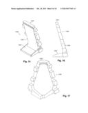
be repetitively reused at subsequent drilling sites for many years. The
system includes a plurality of walls that are assembled together, and
then a water-tight liner is inserted inside the pool created by the
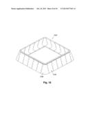
system over the ground and over the side walls, where it is fastened down
to the side walls.Claims:
1. A modular containment system configured for holding and containing a
body of liquid, comprising: a plurality of side walls, each side wall
having interlocking tabs on both ends of the side wall configured to
interlock with interlocking tabs of an adjoining side wall, wherein the
plurality of side walls are interlocked with each other to form an
enclosed open-top volume on the ground, each side wall further configured
with a base portion that extends into the enclosed open-top volume and an
upright portion extending upwards from the base portion to form the
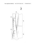
enclosed open-top volume; a flexible liner spread out over the ground
underneath the enclosed open-top volume and over all of the plurality of
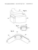
interlocked side walls; and a plurality of fasteners for fastening the
flexible liner to the plurality of interlocked side walls.
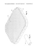
2. The system as recited in claim 1, wherein the plurality of side walls each have an L shape.
3. The system as recited in claim 1, wherein the plurality of fasteners comprise C-shaped clamps that snuggly fit over matching shaped top edges of the plurality of side walls wherein the liner is sandwiched in between the C-shaped clamps and the matching shaped top edges of the plurality of side walls.
4. The system as recited in claim 1, wherein the plurality of fasteners comprise clips that snuggly fit into matching shaped slots on sides of the side balls to thereby sandwich the liner in between the clips and the slots.
5. The system as recited in claim 1, wherein at least some of the plurality of side walls have an L shape in which a base portion fastens to an upright wall portion, wherein the base portion and the upright wall portion are separately manufactured.
Description:
[0001] This application claims priority to U.S. Provisional Patent
Application Ser. No. 61/625,539, which is hereby incorporated by
reference herein.
BACKGROUND AND SUMMARY
[0002] In the oil and gas industry, at a drilling site, there is a need to set up a containment pool near the drilling rig for storing and containing various fluids, such as drilling mud, or other fluids, which might contaminate the surrounding soil. Typical previous containment pools have been excavated in a subterranean manner using heavy equipment to excavate soil to form such pool, and then some type of liner material inserted into the excavated hole to prevent the fluid from seeping into the surrounding soil.
[0003] Naturally, the excavation of the soil with this heavy equipment adds to the expense associated with setting up and operating a drilling rig site, especially in remote areas.
[0004] Embodiments of the present invention provide a modular containment system, which does not require excavation of soil, and thus can be quickly and inexpensively assembled and utilized. Furthermore, the modular barrier system can be repetitively reused at subsequent drilling sites for many years.
BRIEF DESCRIPTION OF THE DRAWINGS
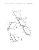
[0005] FIGS. 1-2 illustrate perspective views of a side wall 100 of a containment system configured in accordance with embodiments of the present invention.
[0006] FIG. 3 illustrates in more detail the slots 101, which may be utilized to hold down a vinyl or plastic liner over the top of any of the side walls or other sections of any of the embodiments described herein.
[0007] FIG. 4 illustrates a perspective view of how several side walls can be joined together.
[0008] FIG. 5 illustrates the backside of a corner side wall.
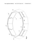
[0009] FIG. 6 illustrates a containment system in accordance with embodiments of the present invention.
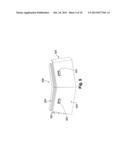
[0010] FIG. 7 illustrates a section of a containment system showing how the liner is held down in place over the tops of side walls.
[0011] FIGS. 8-9 illustrate side walls of another embodiment of the present invention.
[0012] FIG. 10 illustrates a corner side wall configured in accordance with embodiments of the present invention.
[0013] FIG. 11 illustrates an alternative embodiment of a corner side wall configured in accordance with embodiments of the present invention.
[0014] FIG. 12 illustrates connections of side walls with a corner side will in accordance with embodiments of the present invention.
[0015] FIG. 13 illustrates a containment system configured in accordance with embodiments of the present invention showing a liner fastened thereto for containment and holding of a liquid therein.
[0016] FIG. 14 illustrates a C-shaped clamp or clip utilized for holding down a liner on side walls in accordance with embodiments of the present invention.
[0017] FIGS. 15-16 illustrate an alternative embodiment of a side wall configured in accordance with embodiments of the present invention.
[0018] FIG. 17 illustrates a corner side wall configured in accordance with alternative embodiments of the present invention.
[0019] FIG. 18 illustrates a containment system configured in accordance with alternative embodiments of the present invention.
DETAILED DESCRIPTION
[0020] The materials for manufacturing the embodiments of the present invention may be comprised of a plastic, which may be made using rotational or injection molding of each of the pieces of a system.
[0021] Rotational molding is a three-stage, no-pressure, plastic molding process. During the heating stage, the mold slowly rotates in two planes (bi-axial rotation). Heat transfer causes the plastic charge inside the mold to melt and uniformly coat the interior of the mold. During the second stage, the mold moves to the cooling station, where it is cooled by air and/or water spray. In a final load/unload stage, the part is removed from the mold and a new charge of material may be loaded into the mold.
[0022] FIGS. 1-2 illustrate perspective views of a side wall 100 of a containment system configured in accordance with embodiments of the present invention. Slots 101 of the side wall 100 may be included when the side wall 100 is molded, for receipt of a clip to hold down the liner material when the entire system is assembled (see FIG. 7). As the container system is modular, a side wall 100 can be assembled to another modular piece using the interlocking portions 102, 201 formed on a side of a side wall 100, which will fit with the interlocking portions of another side wall portion (e.g., see FIGS. 4 and 6), including the inclusion of some sort of pin (not shown) within the holes down through each of the portions 102, 201 to hold them fast to each other. The side walls 100 may also include a top edge 103, which may be utilized to hold down a liner draped over the top of the side walls with a clip (which may be C-shaped) that may be pressed down on top of the edges 103 to hold down the liner (e.g., see FIGS. 13-14). The side walls 100 have a back portion 104 and an inside wall portion 105. Additionally, and as further shown in FIG. 4, a flap portion 203 may be included on the side walls 100 associated with the interlocking portions 201 so that the gap between the side walls 100 is covered when side walls 100 are assembled together, such as shown in FIG. 6.
[0023] FIG. 2 illustrates a view of a side wall 100, including the interlocking portions 201, which will connect with the portions 102 as shown in FIG. 1 for assembling side walls to each other. FIG. 2 also illustrates the "L-shape" of the side wall 100 where the base portion 202 of the side wall 100 provides stability for the side wall 100 to rest on the ground. When a liner (e.g., see FIG. 13) is installed, the weight of the fluid on top of the base portion 202 is greater than the pressure being applied against the sides 105 of the side walls 100, therefore keeping the walls erect so that they do not tip outward allowing the contained fluid to escape.
[0024] FIG. 3 illustrates a close up perspective view of a portion of a side wall 100 and its slots 101 for receiving clips to hold down a liner (not shown). See FIG. 7 for more detail.
[0025] FIG. 4 shows three side walls 100, which can be assembled to each other using the interlocking portions 102 and 201 on each side wall 100. FIG. 4 also illustrates how a side wall 100 is designed with the interlocking portions 102 on one side of the side wall 100 and the corresponding interlocking portions 201 on the other side.
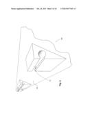
[0026] FIG. 5 illustrates a corner-shaped side wall 500, similarly configured as a straight side wall 100, including possessing one or more slots 501 for receiving a clip for holding a liner in place (e.g., see FIG. 7). Corner-shaped side wall 500 similarly has an outside portion 504, and an inside wall portion (not shown) along with an optional flap 503, and interlocking portions 502, and corresponding interlocking portions at the other end of the side wall (not shown). Furthermore, a corner-shaped side wall 500 may also include a top edge 505 as an alternative means for holding down a liner with a clip attached on top thereof (e.g., see FIGS. 13-14).
[0027] FIG. 6 illustrates an exemplary configuration of a container system with interlocking straight-shaped side walls 100 and corner-shaped side walls 500 with their interlocking portions fastening the side walls to each other. Naturally, any shape of a container system is possible with the various embodiments described herein, and should not be limited to the shape of the system shown in FIG. 6.
[0028] After assembly of any container system described herein, such as those illustrated in FIGS. 6, 13, and 18, a plastic or vinyl liner is then inserted overlaying the ground inside and between the side walls, with the liner then being draped over the side walls of the system. This is further illustrated in FIG. 13, as an example. Such a vinyl or plastic liner is commercially available and well known in the art, and can be manufactured using well known techniques including where multiple sheets of the liner are manufactured and then mold-pressed together at their edges to form any desired shape. After the vinyl cover is draped over the tops of the side walls of an assembled system, either of the fastening means described herein may be utilized to hold down the liner over the top edges, such as utilizing clips into the slots 101, 501, and other slots shown herein, or clips fastening down the liner over the top edges 103, 505, or any of the other top edges described herein.
[0029] For example, FIG. 7 illustrates a sectioned portion showing the back sides 104 of two side walls 100 assembled next to each other with the vinyl sheet 701 draped over the backs of these side walls, and the clips 702 inserted into the slots 101 (hidden from view by the liner 701) to hold down the liner 701. Thereafter, a fluid may then be filled inside the pool of the container system, such as shown in FIG. 13.
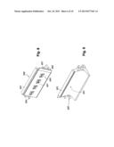
[0030] FIGS. 8-9 illustrate another exemplary containment system, in which side walls 800 are shown. These side walls are of a lower height than side walls 100, for assembling together to form a containment system that has lower sides. Essentially, labeled items 801-806, and 808 are similar to items 101-105, 201, and 203, respectively.
[0031] FIG. 10 illustrates a corner-shaped side wall 1000, with a clip receiving slot 1001, which is designed to interlock with side walls 800. The corner-shaped side wall 1000 may be similarly designed as the corner-shaped side wall 500. The corner-shaped side wall may also include a top edge 1003 similar to the top edges 103, 505, and 803 for retaining a liner over the top of the corner-shaped side wall utilizing a clip such as shown in FIG. 14.
[0032] FIG. 11 illustrates an alternative embodiment of a corner-shaped side wall 1100, which is similar to the corner-shaped side wall 1000, except that it utilizes the side tab portions 1102 and 1103 to interconnect using pins (not shown) with the side walls 800, such as illustrated in FIG. 12. It should be noted that corner-shaped side wall 1100 is shown not including a top edge 1003, such as shown in FIG. 10. Additionally, the corner-shaped side wall 1100 has a straight inside wall, and does not have an L shape, such as the corner-shaped side wall 1000, which has an L shape similar to the corner-shaped side wall 500. Nevertheless, a corner-shaped side wall 1000 may be utilized for assembly with side walls 800 in a manner similar to what is shown in FIG. 12.
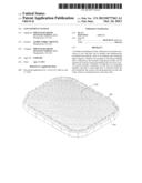
[0033] FIG. 13 illustrates an exemplary containment system assembled in a fashion with multiple side walls on the straight sides of the system and the corner-shaped side walls at each corner. The containment system illustrated in FIG. 13 also shows a liner 1301 installed within the interior of the system and held in place over the tops of the side walls with clips 1401 attached over the tops of each of the side walls to hold down the liner 1301. As can be seen in FIG. 13, a fluid 1302 is satisfactorily contained within the enclosed system.
[0034] FIG. 14 illustrates an exemplary C-shaped clip 1401, which may be utilized to snuggly fasten down a liner over the top edges of any of the side walls described herein. The exact shape of the clip 1401 should not be limited to the shape illustrated in FIG. 14. Nevertheless, the inside shape of the clip 1401 should have a similar shape as the outside shape of any of the top edges of the side walls described herein so that a liner is sandwiched in between the clip and the top edge when the clip is snapped over the top edge of the side walls, such as illustrated in FIG. 13.
[0035] It should be noted that the example of a liner placed inside a containment system and then draped over the sides of the side walls and fastened down as illustrated in FIG. 13 may be accomplished for any of the containment systems described herein, and any variations thereof. For example, the liner illustrated in FIG. 13 may be fastened down using the clips shown in FIG. 7 that have the liner sandwiched between the slots (not shown) and the clip. Such clips shown in FIG. 7 may be manufactured from any rigid material, such as PVC or metal pipe.
[0036] FIGS. 15-16 illustrate an alternative embodiment of a side wall, which is similarly shaped as the side walls 100. However, the upright portion 1501 is separately manufactured (e.g., using rotational or injection molding) from the base portion 1502, and then the upright portion 1501 and the base portion 1502 may be assembled together, such as by using a pin or slot to fasten them together. The side walls 1500 also may include a top edge 1503 for receiving a clip 1401. Alternatively, a slot (not shown) such as the slots 101 may be integrally formed on the side of one of the upright side wall portions 1501.
[0037] FIG. 17 illustrates a corner side wall 1700 for assembling with the side walls 1500.
[0038] FIG. 18 illustrates an example of a containment system 1800 assembled using the side walls 1500 and corner side walls 1700.
User Contributions:
Comment about this patent or add new information about this topic:
Images included with this patent application:
 |  |
 |  |
 |  |
 |  |
 |  |
 |
| Similar patent applications: | |
| Date | Title |
|---|---|
| 2011-09-01 | Container system |
| 2013-11-28 | One piece reversible closure and container system |
| 2013-11-21 | Hot fill container having superior crush resistance |
| 2010-06-24 | Tank ventilation system |
| 2011-06-02 | Container assembly |
| New patent applications in this class: | |
| Date | Title |
|---|---|
| 2015-12-03 | Portable water supply |
| 2015-11-12 | Containment system |
| 2015-11-12 | Molded plastic water storage tank |
| 2015-04-30 | Modular fluid storage tank |
| 2015-03-19 | Liquid storage tank formed of a plurality of panels |
| Top Inventors for class "Receptacles" | |
| Rank | Inventor's name |
|---|---|
| 1 | Daniel Lee Bizzell |
| 2 | Frank Yang |
| 3 | Terry Vovan |
| 4 | William P. Apps |
| 5 | Lowell L. Wood, Jr. |