Patent application title: STRAP ASSEMBLY ACROSS THE FACE OF A SHOE
Inventors:
Robert Schein (Indian Wells, CA, US)
John Matthew-Diefenbach (Indian Wells, CA, US)
IPC8 Class: AA43C1900FI
USPC Class:
24302
Class name: Buckles, buttons, clasps, etc. plural fasteners having intermediate flaccid connector strap connector
Publication date: 2013-09-12
Patent application number: 20130232734
Abstract:
This is directed to systems, processes, machines, and other means that
mechanically couple a shoe strap to a shoe. The invention can hold shoe
laces tied and provide the user with a marketing area.Claims:
1. A strap assembly across a face of a shoe comprising, a shoe strap
mechanically coupled to a first hook; where the first hook can be
mechanically coupled to a first shoe eyelet; and a second hook
mechanically coupled to the shoe strap; where the second hook can be
mechanically coupled to a second shoe eyelet.
2. The strap assembly of claim 1, further comprising, where the first hook is metal; where the second hook is metal; where the shoe strap is plastic.
3. The strap assembly of claim 1, further comprising, where the first hook is plastic; where the second hook is plastic; where the shoe strap is plastic.
4. The strap assembly of claim 1, further comprising, where the shoe strap further comprises a marketing area.
5. The strap assembly of claim 1, further comprising, where the first hook is mechanically coupled to the shoe strap by a first rivet and a second rivet; and where the second hook is mechanically coupled to the shoe strap by a third rivet and a fourth rivet.
Description:
CROSS REFERENCE TO RELATED APPLICATIONS
[0001] This application claims priority to provisional application 61/341,033 filed on Mar. 9, 2011
STATEMENT REGARDING FEDERALLY SPONSORED RESEARCH OR DEVELOPMENT
[0002] Not Applicable
THE NAMES OF PARTIES TO A JOINT RESEARCH AGREEMENT
[0003] Not Applicable
INCORPORATION BY REFERENCE OF MATERIAL SUBMITTED ON A COMPACT DISC
[0004] Not Applicable
FIELD OF THE INVENTION
[0005] This invention relates to a strap that fits across the face of a shoe.
BACKGROUND OF THE INVENTION
[0006] There are a variety of theories of how to hold shoe laces tied which involve technology which teaches away from that involved in the present invention. For example, the shoelace holder proposed by Hubbard in U.S. Pat. App. 2009/0293240 A1 involves installing a hook and loop fastener across the face of the shoe. This requires permanently altering the shoe in order to install the Hubbard device. The attachment device proposed by Simon in U.S. Pat. App. 2008/0229621 A1 involves inserting a large device over the shoe laces that covers the shoe laces in their entirety. The lace securing apparatus proposed by Perler in U.S. Pat. No. 7,404,242 B1 proposes a large clip that covers the shoe laces in a manner similar to Simon. In each case, no device teaches using hooks in shoe eyelets to secure a device that can both secure the shoe laces and provide a marketing area.
BRIEF SUMMARY OF THE INVENTION
[0007] The present invention includes methods, systems, and other means for a strap assembly comprising a shoe strap which further comprises a marketing area. The shoe strap is mechanically coupled to a first hook by a first rivet and a second rivet. The shoe strap is also mechanically coupled to a second hook by a third rivet and a fourth rivet.
BRIEF DESCRIPTION OF THE SEVERAL VIEWS OF THE DRAWINGS
[0008] Having thus described the invention in general terms, reference will now be made to the accompanying drawings, which are not necessarily drawn to scale, and wherein:
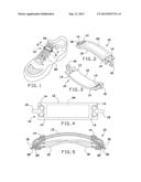
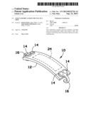
[0009] FIG. 1 is a perspective view of the invention shown in use.
[0010] FIG. 2 is a perspective view of the invention.
[0011] FIG. 3 is a perspective view of the invention.
[0012] FIG. 4 is a top view of the invention.
[0013] FIG. 5 is a detailed section view of the invention taken along line 5-5 in FIG. 1.
DETAILED DESCRIPTION OF THE INVENTION
[0014] Embodiments of the present invention overcome many of the obstacles associated with securing shoe laces and providing a marketing area, and now will be described more fully hereinafter with reference to the accompanying drawings that show some, but not all embodiments of the claimed inventions. Indeed, the invention may be embodied in many different forms and should not be construed as limited to the embodiments set forth herein. Rather, these embodiments are provided so that this disclosure will satisfy applicable legal requirements. Like numbers refer to like elements throughout.
[0015] FIG. 1 shows a perspective view of the strap assembly 10 which rests across the face of shoe 20. Here a user desires to keep shoe laces 18 from becoming untied and simultaneously providing a marketing area which is shown in more detail in FIG. 2. A section view along line 5-5 is shown in FIG. 5.
[0016] FIG. 2 shows strap assembly 10 in more detail. Shoe strap 12 is mechanically coupled to first hook 16 by first rivet 14 and second rivet 14. Shoe strap 12 is further mechanically coupled to second hook 16 by third rivet 14 and fourth rivet 14. Shoe strap 12 further comprises marketing area 24 that can be used to display messages according to manufacturer or user preference.
[0017] FIG. 2 shows another view of strap assembly 10. As noted above, shoe strap 12 is mechanically coupled to first hook 16 by first rivet 14 and second rivet 14. Shoe strap 12 is further mechanically coupled to second hook 16 by third rivet 14 and fourth rivet 14.
[0018] While a variety of materials can be used for strap assembly 10, it may be useful to make shoe strap 12 of a molded flexible plastic or silicone. First hook 16 and second hook 16 can be made of metal or plastic, but the material should be sufficiently flexible such that first hook 16 and second hook 16 can be mechanically coupled to first shoe eyelet 22 and second shoe eyelet 22 as shown in FIG. 5.
[0019] FIG. 3 and FIG. 4 show more views of strap assembly 10. As noted above, shoe strap 12 is mechanically coupled to first hook 16 by first rivet 14 and second rivet 14. Shoe strap 12 is further mechanically coupled to second hook 16 by third rivet 14 and fourth rivet 14. Shown here, shoe strap further comprises marketing area 24. The strap assembly can be made in a wide variety of dimensions to accommodate user preference.
[0020] FIG. 5 shows a section view along line 5-5 in FIG. 1. To use the device, the user ties shoe laces 18 in a manner which is well known. After shoe laces 18 are tied the user inserts first hook 16 through first shoe eyelet 22. The user then stretches shoe strap 12 over the face of shoe 20 and inserts second hook 16 through second shoe eyelet 22. At this point, first hook 16 can be bent mechanically coupling first hook 16 to first shoe eyelet 22. Similarly, second hook 16 can be bent mechanically coupling second hook 16 to second shoe eyelet 22.
User Contributions:
Comment about this patent or add new information about this topic:
| People who visited this patent also read: | |
| Patent application number | Title |
|---|---|
| 20150159806 | PRESSURE VESSEL WITH METALLIC LINER AND TWO FIBER LAYERS OF DIFFERENT MATERIAL |
| 20150159805 | MOUNTING UNIT OF DRIVING DEVICE FOR VEHICLE |
| 20150159804 | SIT-STAND WORKSTATION WITH DISPLAY SUPPORT APPARATUS |
| 20150159803 | VARIABLE HEIGHT TROLLEY AND HEIGHT DISPLAYING ASSEMBLY THEREOF |
| 20150159802 | PORTABLE MODULAR MONOPOLE TOWER FOUNDATION |
Images included with this patent application:
 |  |
| Similar patent applications: | |
| Date | Title |
|---|---|
| 2013-12-26 | Spring fastener with highly improved lever/angle pulling force |
| 2013-12-26 | Money clip and method of operating same |
| 2009-01-22 | Intravenous tube organizer |
| 2013-08-08 | Fastener clip assembly |
| New patent applications in this class: | |
| Date | Title |
|---|---|
| 2016-12-29 | Laundry sock/garment snare |
| 2016-03-10 | Load securing assembly |
| 2015-05-07 | Dual closed-ended zippers mechanism reusable fastener |
| 2015-04-02 | Pinata rope |
| 2015-02-05 | Quick release support system |
| Top Inventors for class "Buckles, buttons, clasps, etc." | |
| Rank | Inventor's name |
|---|---|
| 1 | Keiichi Keyaki |
| 2 | Andreas Hörtnagl |
| 3 | Toshio Iwahara |
| 4 | Joachim Fiedler |
| 5 | Allison S. Conner |