Patent application title: DUST REMOVAL SYSTEM FOR LED STRIP AND APPRATUS WITH THE DUST REMOVAL SYSTEM
Inventors:
Chih-Chen Lai (New Taipei, TW)
Chih-Chen Lai (New Taipei, TW)
Hon Hai Precision Industry Co., Ltd.
Hon Hai Precision Industry Co., Ltd.
Assignees:
HON HAI PRECISION INDUSTRY CO., LTD.
IPC8 Class: AA47L700FI
USPC Class:
15345
Class name: Machines with air blast or suction air blast with suction
Publication date: 2013-08-29
Patent application number: 20130219653
Abstract:
A apparatus for treating an LED strip includes a warming zone, a dust
removal system disposed in the warming zone, a belt transporting the LED
strip through the dust removal system, a high temperature zone and a
cooling zone. The dust removal system includes an airflow generating
device producing an airflow removing dust away from the LED strip when
the LED strip passes through the airflow generating. The high temperature
zone performs a reflow soldering to the LED strip which has a plurality
of LEDs mounted thereon.Claims:
1. A dust removal system for cleaning an LED (light emitting diode)
strip, comprising: an airflow generating device, wherein the airflow
generating device produces an airflow to remove dust away from the LED
strip when the LED strip passes through the airflow generating device.
2. The dust removal system of claim 1, wherein the airflow generating device comprises an electrostatic eliminating bar to remove electrostatic charges of the LED strip.
3. The dust removal system of claim 2, wherein the electrostatic eliminating bar comprises a brush to disturb the airflow.
4. The dust removal system of claim 1, wherein the airflow generating device comprises an upper airflow generating device and a lower airflow generating device, the LED strip passing through a space between the upper airflow generating device and the lower airflow generating device.
5. The dust removal system of claim 4, wherein the upper airflow generating device comprises a blowing port blowing the air flow to the LED strip.
6. The dust removal system of claim 5, wherein the upper airflow generating device comprises an electrostatic eliminating bar located at a middle of a bottom end of the blowing port.
7. The dust removal system of claim 6, wherein the upper airflow generating device comprises a brush near the bottom end of the blowing port.
8. The dust removal system of claim 5, wherein the lower airflow generating device comprises a sucking port corresponding to the blowing port.
9. The dust removal system of claim 8, wherein the lower airflow generating device comprises an electrostatic eliminating bar located at a middle of a top end of the sucking port.
10. The dust removal system of claim 9, wherein the lower airflow generating device comprises a brush near the top end of the sucking port.
11. A apparatus for treating an LED strip, comprising: a warming zone; a dust removal system disposed in the warming zone; a belt transporting the LED strip through the dust removal system; wherein the dust removal system comprises an airflow generating device producing an airflow removing dust away from the LED strip when the LED strip passes through the airflow generating.
12. The apparatus of claim 11, further comprising a high temperature zone and a cooling zone, wherein the LED strip is transported by the belt to sequentially pass through the dust removal system in the warming zone, the high temperature zone and the cooling zone.
13. The apparatus of claim 11, wherein the temperature of the warming zone is lower than 100.degree. C., and the LED strip being dried when the LED strip passes through the warming zone.
14. The apparatus of claim 11, wherein the LED strip is reflowed when the LED strip passes through the high temperature zone.
15. The apparatus of claim 11, wherein the airflow generating device comprises an upper airflow generating device and a lower airflow generating device, the LED strip passing through a space between the upper airflow generating device and the lower airflow generating device of the dust removal system.
16. The apparatus of claim 15, wherein the upper airflow generating device comprises a blowing port blowing the air flow to the LED strip.
17. The apparatus of claim 16, wherein the upper airflow generating device comprises an electrostatic eliminating bar located at a middle of a bottom end of the blowing port.
18. The apparatus of claim 17, wherein the upper airflow generating device comprises a brush near the bottom end of the blowing port.
19. The apparatus of claim 16, wherein the lower airflow generating device comprises a sucking port corresponding to the blowing port.
20. The apparatus of claim 19, wherein the lower airflow generating device comprises a brush near a top end of the sucking port.
Description:
TECHNICAL FIELD
[0001] The present disclosure relates to a dust removal system, and more particularly, to a dust removal system for cleaning LED (light emitting diode) strips and an apparatus with the dust removal system.
DESCRIPTION OF RELATED ART
[0002] LEDs have many advantages, such as high luminosity, low operational voltage, low power consumption, compatibility with integrated circuits, easy driving, long term reliability, and environmental friendliness. Such advantages have promoted the wide use of LEDs as a light source. Nowadays, LED strips are commonly applied in lamps. Generally, the LEDs of the LED strips are encapsulated by resin. However, dust may be adhered on the outer surfaces of the resin encapsulants of the LEDs. As a result, the brightness as well as the appearance of the LED strips are unfavorably affected by the dust.
[0003] What is needed, therefore, is a dust removal system for an LED strip and apparatus with the dust removal system which can overcome the described limitations.
BRIEF DESCRIPTION OF THE DRAWINGS
[0004] Many aspects of the present disclosure can be better understood with reference to the following drawings. The components in the drawings are not necessarily drawn to scale, the emphasis instead being placed upon clearly illustrating the principles of the present disclosure. Moreover, in the drawings, like reference numerals designate corresponding parts throughout the views.
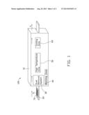
[0005] FIG. 1 is a schematic view of an apparatus with a dust removal system in accordance with an embodiment of the present disclosure.
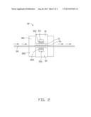
[0006] FIG. 2 is a schematic view of a structure of the dust removal system of the apparatus shown in FIG. 1.
DETAILED DESCRIPTION
[0007] Referring to FIG. 1, an apparatus 100 with a dust removal system 30 for an LED strip 70 in accordance with an embodiment of the present disclosure is shown. The apparatus 100 includes an operating zone 10 and a transporting belt 20 extending through the operating zone 10. The operating zone 10 includes a warming zone 40, a high temperature zone 50 and a cooling zone 60. The dust removal system 30 is located in the warming zone 40. The transporting belt 20 moves along a direction "a" shown in FIG. 1. The LED strip 70 with a plurality of LEDs 71 mounted thereon is disposed on the transporting belt 20. The LED strip 70 is transported by the transporting belt 20 to sequentially pass the warming zone 40, the high temperature zone 50 and the cooling zone 60 and leave the apparatus 100. Temperature of the warming zone 40 is lower than 100° C. .
[0008] The high temperature zone 50 can provide a temperature higher than 200° C., so that the LED strip 70 can be reflowed in the high temperature zone 50.
[0009] Referring to FIG. 2, the dust removal system 30 includes an upper airflow generating device 301 and a lower airflow generating device 302. The transporting belt 20 passes through a middle of the dust removal system 30, between the upper airflow generating device 301 and the lower airflow generating device 302. The upper airflow generating device 301 includes a blowing port 31 which blows air to the transporting belt 20. That is to say, the blowing port 31 faces downwardly. The upper airflow generating device 301 includes an electrostatic eliminating bar 311 located at a middle of a bottom end of the blowing port 31. The electrostatic eliminating bar 311 can be fastened to a top plate or side plates of the blowing port 31. A cross-sectional dimension of the electrostatic eliminating bar 311 is smaller than that of the blowing port 31. Thus, the electrostatic eliminating bar 311 will not block the blowing port 31 from blowing air to the transporting belt 20. The upper airflow generating device 301 includes a brush 312 near the bottom end of the blowing port 31. The lower airflow generating device 302 includes a sucking port 32 corresponding to the blowing port 31 of the upper airflow generating device 301, which sucks air from the transporting belt 20. The lower airflow generating device 302 includes an electrostatic eliminating bar 321 located at a middle of a top end of the sucking port 32. The lower airflow generating device 302 includes a brush 322 near the top end of the sucking port 32. Preferably, the dust removal system 30 will not extend to the high temperature zone 50 in order to avoid damage to the upper airflow generating device 301 and the lower airflow generating device 302 under a high temperature environment. Furthermore, the separation of the dust removal system 30 and the high temperature zone 50 can protect the high temperature zone 50 from being affected by air flow produced by the upper airflow generating device 301 and the lower airflow generating device 302.
[0010] The LED strip 70 enters the operating zone 10 by the transporting belt 20 and arrives at the dust removal system 30 in the warming zone 40. Due to heating of the warming zone 40 to the LED strip 70, the LED strip 70 is dried. After that the LED strip 70 has been warmed and dried in the warming zone 40, adhesion force of the dust on the LED strip 70 becomes poor. The blowing port 31 can easily blow dust away from the LED strip 70. At the same time, the sucking port 32 sucks the dust blown by the blowing port 31 to leave the operating zone 10. Therefore, dust attached on the LED strip 70 is cleaned. In the process of the LED strip 70 passing through the dust removal system 70, the electrostatic eliminating bars 312, 322 remove electrostatic charges on the LED strip 70 in order to avoid electrostatic from absorbing dust. The brushes 312, 322 of the blowing port 31 and the sucking port 32 disturb the air flow from the blowing port 31 to the sucking port 32, to enable the dust to more easily float around from the outer surfaces of the encapsulants covering LED chips of the LEDs 71 to thereby obtain a better dust removal effect.
[0011] The dust removal system 30 is not limited to include only one air blowing port 31 and only one sucking port 32. A plurality of air blowing ports 31 and air sucking ports 32 may be used according to a length of the LED strip 70. Alternatively, each blowing port 31 may match with several sucking ports 32, or each sucking port 32 may match with several blowing ports 31. Furthermore, the dust removal system 30 can include only one of the blowing port 31 and sucking port 32 if only one of the blowing port 31 and sucking port 32 can provide sufficient air flow for cleaning the dust from the LED strip 70. However, the sucking port 32 is preferable since the sucking port 32 can provide a chamber to collect the drawn dust.
[0012] Alternatively, the brushes 312, 322 can be replaced with other airflow-disturbing devices such as fins arranged in parallel or a mesh with small holes. A distance between the two brushes 312, 322 can be reduced, so that the brush 312 can directly brush a top surface of the LED strip 70 and the brush 322 can directly brush a bottom surface of the LED strip 70. As a result, the dust on the LED strip 70 can be cleaned more easily.
[0013] It is believed that the present disclosure and its advantages will be understood from the foregoing description, and it will be apparent that various changes may be made thereto without departing from the spirit and scope of the present disclosure or sacrificing all of its material advantages, the examples hereinbefore described merely being preferred or exemplary embodiments.
User Contributions:
Comment about this patent or add new information about this topic:
| People who visited this patent also read: | |
| Patent application number | Title |
|---|---|
| 20140085775 | ELECTROLYTIC CAPACITOR AND METHOD OF MANUFACTURING THE SAME |
| 20140085774 | ELECTROLYTE AND ELECTRIC DOUBLE-LAYER CAPACITOR USING SAME |
| 20140085773 | HYBRID ELECTROCHEMICAL ENERGY STORAGE DEVICE |
| 20140085772 | DIRECT CURRENT CAPACITOR MODULE |
| 20140085771 | QUATERNARY DATA-STORAGE MATERIALS AND THE PREPARATION METHOD THEREOF |
Images included with this patent application:
 |  |
 |
| Similar patent applications: | |
| Date | Title |
|---|---|
| 2013-08-15 | Oral care instrument and package therefore |
| 2013-08-22 | Adapter for windshield wiper assembly |
| 2013-05-23 | Apparatus and method for storing and reusing remnants of soap |
| 2013-05-23 | Toydozer.tm. scoop and gatherer set |
| 2013-09-05 | Robot cleaner with improved dust collector |
| New patent applications in this class: | |
| Date | Title |
|---|---|
| 2016-04-07 | Systems and methods for treating substrates with cryogenic fluid mixtures |
| 2016-03-31 | Air gun with sucking function |
| 2014-01-09 | Cleaning device |
| 2013-10-31 | Vacuum cleaner with blower and flexible head for improved particulate removal |
| 2013-10-24 | Hand-held blower devices with vacuum function |
| New patent applications from these inventors: | |
| Date | Title |
|---|---|
| 2016-06-30 | Illuminating device |
| 2015-11-12 | Method for manufacturing led die |
| 2015-10-01 | Optical fiber connector with optical fiber holder received in rj45 plug |
| 2015-08-27 | Optical communication module and method for assembling same |
| 2015-08-13 | Method for adjusting circuit board |
| Top Inventors for class "Brushing, scrubbing, and general cleaning" | |
| Rank | Inventor's name |
|---|---|
| 1 | Wayne Ernest Conrad |
| 2 | Xavier Boland |
| 3 | Helmut Depondt |
| 4 | Robert Moskovich |
| 5 | James Dyson |