Patent application title: HEAT DISSIPATING APPARATUS
Inventors:
Shuang Fu (Shenzhen City, CN)
Shuang Fu (Shenzhen City, CN)
IPC8 Class: AF28D1502FI
USPC Class:
16510421
Class name: Intermediate fluent heat exchange material receiving and discharging heat liquid fluent heat exchange material utilizing change of state
Publication date: 2013-07-04
Patent application number: 20130168051
Abstract:
A heat dissipating apparatus includes a base, a first fin assembly, a
second fin assembly, a first heat pipe, and a second heat pipe. The first
fin assembly and the second fin assembly are disposed on the top surface
of the base. The first fin assembly defines a first through hole. The
second fin assembly defines a second through hole. The second fin
assembly is a structural mirror image of the first fin assembly. The
first heat pipe includes a first contacting portion in contact with the
base and a second contacting portion received in the first through hole
of the first fin assembly. The second heat pipe includes a third
contacting portion in contact with the base and a fourth contacting
portion received in the second through hole of the second fin assembly.Claims:
1. A heat dissipating apparatus, comprising: a base comprising a top
surface and a bottom surface configured for contacting an electronic
heat-generating component; a first fin assembly and a second fin assembly
disposed on the top surface of the base, wherein the first fin assembly
defines a first through hole, the second fin assembly defines a second
through hole, and the second fin assembly is a structural mirror image of
the first fin assembly; a first heat pipe comprising a first contacting
portion in contact with the base and a second contacting portion received
in the first through hole of the first fin assembly; and a second heat
pipe comprising a third contacting portion in contact with the base and a
fourth contacting portion received in the second through hole of the
second fin assembly.
2. The heat dissipating apparatus of claim 1, wherein the first heat pipe further comprises a first connecting portion interconnecting the first contacting portion and the second contacting portion, and the second heat pipe further comprises a second connecting portion interconnecting the third contacting portion and the fourth contacting portion.
3. The heat dissipating apparatus of claim 2, wherein the first heat pipe and the second heat pipe are U-shaped.
4. The heat dissipating apparatus of claim 1, wherein the first heat pipe is located in a first plane inclined upward from the top surface of the base, and the second heat pipe is located in a second plane inclined upward from the top surface of the base.
5. The heat dissipating apparatus of claim 4, wherein the first plane and the second plane intersect at the top surface of the base.
6. The heat dissipating apparatus of claim 1, wherein the first heat pipe and the second heat pipe have a same structure.
7. The heat dissipating apparatus of claim 1, wherein a first receiving groove and a second receiving groove are defined in the top surface of the base, the first contacting portion of the first heat pipe is received in the first receiving groove, and the third contacting portion of the second heat pipe is received in the second receiving groove.
8. The heat dissipating apparatus of claim 7, wherein a first cutout groove is defined in a lower surface of the first fin assembly, the first receiving groove together with the first cutout groove define a first receiving hole, and the first contacting portion of the first heat pipe is received in the first receiving hole.
9. The heat dissipating apparatus of claim 7, wherein a second cutout groove is defined in a lower surface of the second fin assembly, the second receiving groove together with the second cutout groove define a second receiving hole, and the third contacting portion of the second heat pipe is received in the second receiving hole.
10. The heat dissipating apparatus of claim 7, wherein the first receiving groove and the second receiving groove are parallel to each other.
11. The heat dissipating apparatus of claim 7, wherein the first receiving groove and the second receiving groove extend lengthwise along the base.
12. The heat dissipating apparatus of claim 1, wherein the first through hole extends along a longer dimension of the first fin assembly, and the second through hole extends along a longer dimension of the second fin assembly.
13. The heat dissipating apparatus of claim 1, wherein a first side surface of the first fin assembly is attached to a second side surface of the second fin assembly.
14. The heat dissipating apparatus of claim 10, wherein the first receiving groove and the second receiving groove are arranged in a middle of the top surface of the base.
15. The heat dissipating apparatus of claim 1, wherein the first fin assembly and the second fin assembly comprise a plurality of parallel fins, and extending directions of the first through hole and the second through hole are perpendicular to the plurality of parallel fins.
16. The heat dissipating apparatus of claim 2, wherein the first connecting portion of the first heat pipe is opposite to the second connecting portion of the second heat pipe.
Description:
REFERENCE TO RELATED APPLICATIONS
[0001] This application claims all benefits accruing under 35 U.S.C. §119 from China Patent Application No. 201110452525.5, filed on Dec. 30, 2011 in the State Intellectual Property Office of China, the contents of the China Application are hereby incorporated by reference.
BACKGROUND
[0002] 1. Technical Field
[0003] The present disclosure generally relates to heat dissipating apparatuses, and particularly relates to a heat dissipating apparatus having two fin assemblies being structural mirror images of each other.
[0004] 2. Description of Related Art
[0005] Electronic components, such as central processing units (CPUs) in computers, generate a lot of heat during operations. Excess heat may cause deterioration in the operational stability of the electronic components and may damage the electronic components. Thus, excess heat must be removed quickly to maintain an acceptable operating temperature of the electronic components in the computer. One method for removing heat from an electronic component is by mounting a heat dissipating apparatus on the electronic component. However, the dissipating apparatus of related art may be inadequate to satisfy the ever-increasing demand for heat dissipation.
[0006] Therefore, there is room for improvement within the art.
BRIEF DESCRIPTION OF THE DRAWINGS
[0007] Many aspects of the embodiments can be better understood with reference to the following drawings. The components in the drawings are not necessarily drawn to scale, the emphasis instead being placed upon clearly illustrating the principles of the embodiments. Moreover, in the drawings, like reference numerals designate corresponding parts throughout the several views.
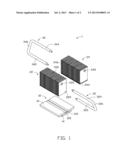
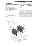
[0008] FIG. 1 is an exploded, isometric view of a heat dissipating apparatus in accordance with an embodiment.
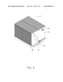
[0009] FIG. 2 is an assembled view of the heat dissipating apparatus of FIG. 1.
DETAILED DESCRIPTION
[0010] The disclosure is illustrated by way of example and not by way of limitation in the figures of the accompanying drawings in which like references indicate similar elements. It should be noted that references to "an" or "one" embodiment in this disclosure are not necessarily to the same embodiment, and such references mean "at least one."
[0011] FIG. 1 shows a heat dissipating apparatus 1 in accordance with an embodiment. The heat dissipating apparatus 1 includes a base 10, a first fin assembly 22, a second fin assembly 24, a first heat pipe 32, and a second heat pipe 34.
[0012] The base 10 includes a top surface 12 and a bottom surface 14. The bottom surface 14 of the base 10 may contact a heat delivery surface of an electronic heat-generating component (not shown), such as a central processing unit (CPU) or a graphic processing unit (GPU), and take heat from the heat-generating component. The base 10 defines a first receiving groove 122 and a second receiving groove 124 on the top surface 12. Both the first receiving groove 122 and the second receiving groove 124 extend lengthwise along the base 10 and across the top surface 12 of the base 10. The first receiving groove 122 and the second receiving groove 124 are arranged in the middle of the top surface 12 of the base 10 and are parallel to each other.
[0013] The first fin assembly 22 includes a plurality of parallel fins. The first fin assembly 22 defines a first through hole 222. The first through hole 222 extends through the first fin assembly 22 and along the longer dimension of the first fin assembly 22. The first through hole 222 is perpendicular to the fins of the first fin assembly 22. The first fin assembly 22 defines a first cutout groove 224 in its bottom surface which matches the internal shape of the first receiving groove 122 of the base 10. The first cutout groove 224 extends along a longer side of the first fin assembly 22 and is perpendicular to the fins of the first fin assembly 22. The first cutout groove 224 is parallel to the first through hole 222.
[0014] The second fin assembly 24 is a structural mirror image of the first fin assembly 22. The second fin assembly 24 defines a second through hole 242. The second through hole 242 extends through the second fin assembly 24 and along the longer dimension of the second fin assembly 24. The second through hole 242 is perpendicular to the fins of the second fin assembly 24. The second fin assembly 24 defines a second cutout groove 244 in its bottom surface which matches the internal shape of the second receiving groove 124 of the base 10. The second cutout groove 244 extends along a longer side of the second fin assembly 24 and is perpendicular to the fins of the second fin assembly 24. The second cutout groove 244 is parallel to the second through hole 242.
[0015] The first heat pipe 32 is U-shaped. The first heat pipe 32 includes a first contacting portion 322, a second contacting portion 324, and a first connecting portion 326. The first contacting portion 322 and the second contacting portion 324 are perpendicular to the first connecting portion 326 and extend from two opposite ends of the first connecting portion 326. The first contacting portion 322 and the second contacting portion 324 are parallel to each other. The first contacting portion 322, the second contacting portion 324, and the first connecting portion 326 are substantially located in a same plane.
[0016] The second heat pipe 34 is the same as the first heat pipe 32. The second heat pipe 34 is also U-shaped. The second heat pipe 34 includes a third contacting portion 342, a fourth contacting portion 344, and a second connecting portion 346. The third contacting portion 342 and the fourth contacting portion 344 are perpendicular to the second connecting portion 346 and extend from two opposite ends of the second connecting portion 346. The third contacting portion 342 and the fourth contacting portion 344 are parallel to each other. The third contacting portion 342, the fourth contacting portion 344, and the second connecting portion 346 are substantially located in a same plane.
[0017] Referring to FIG. 2, in assembly, the first fin assembly 22 and the second fin assembly 24 are disposed on the top surface 12 of the base 10. The first fin assembly 22 and the second fin assembly 24 are parallel to each other. A first side surface 226 of the first fin assembly 22 is attached to a second side surface 246 of the second fin assembly 24.
[0018] The first cutout groove 224 of the first fin assembly 22 is aligned with the first receiving groove 122 of the base 10. The first cutout groove 224 and the first receiving groove 122 together define a first receiving hole (not labeled). The second cutout groove 244 of the second fin assembly 24 is aligned with the second receiving groove 124 of the base 10. The second cutout groove 244 and the second receiving groove 124 together define a second receiving hole (not labeled).
[0019] The second contacting portion 324 the first heat pipe 32 is inserted into the at first through hole 222 of the first fin assembly 22. The diameter of the cross section of the second contacting portion 324 is substantially the same as the diameter of the first through hole 222, so that the second contacting portion 324 is in contact with the inner surface(s) of the first through hole 222 when the second contacting portion 324 is received in the first through hole 222. Similarly, the fourth contacting portion 344 of the second heat pipe 34 is received in the second through hole 242 of the second fin assembly 24 and is in contact with the inner surface(s) of the second through hole 242.
[0020] The first contacting portion 322 of the first heat pipe 32 is received in the first receiving hole. The third contacting portion 342 of the second heat pipe 34 is received in the second receiving hole. Thus, the first contacting portion 322 of the first heat pipe 32 is in contact with the base 10 and the second contacting portion 324 of the first heat pipe 32 is in contact with the first fin assembly 22. The third contacting portion 342 of the second heat pipe 34 is in contact with the base 10 and the fourth contacting portion 344 of the second heat pipe 34 is in contact with the second fin assembly 24. The first heat pipe 22 is located in a first plane inclined upward from the top surface 12 of the base 10. The second heat pipe 34 is located in a second plane inclined upward from the top surface 12 of the base 10. The first plane and the second plane intersect at the top surface 12 of the base 10. The first connecting portion 326 of the first heat pipe 32 is opposite to the second connecting portion 346 of the second heat pipe 34.
[0021] It is to be understood, however, that even though numerous characteristics and advantages have been set forth in the foregoing description of embodiments, together with details of the structures and functions of the embodiments, the disclosure is illustrative only and changes may be made in detail, especially in the matters of shape, size, and arrangement of parts within the principles of the disclosure to the full extent indicated by the broad general meaning of the terms in which the appended claims are expressed.
User Contributions:
Comment about this patent or add new information about this topic:
| People who visited this patent also read: | |
| Patent application number | Title |
|---|---|
| 20130167598 | TRANSMISSION MECHANISM ADAPTED TO AN ELECTRO-MECHANICAL LOCK AND ELECTRO-MECHANICAL LOCK THEREWITH |
| 20130167597 | Multi-Point Lock Having A Flush-Mount Cylinder |
| 20130167596 | WASHING MACHINE |
| 20130167595 | P-ELEMENT DOPED LASER MEDIUM APPARATUS AND METHOD |
| 20130167594 | POLARIZATION CONTROLLING OPTICAL FIBER PREFORM AND PREFORM FABRICATION METHODS |
Images included with this patent application:
 |  |
 |
| Similar patent applications: | |
| Date | Title |
|---|---|
| 2011-05-05 | Heat dissipating cavity |
| 2014-03-20 | Bidirectional heat dissipation structure |
| 2014-03-20 | Heat dissipation structure |
| 2011-04-14 | Heat dissipating blower |
| 2012-09-13 | Heat sink apparatus |
| New patent applications in this class: | |
| Date | Title |
|---|---|
| 2022-05-05 | Heat pipe and heat dissipation structure |
| 2016-12-29 | Cooling electronic devices in a data center |
| 2016-12-29 | Two-phase cooling devices with low-profile charging ports |
| 2016-12-29 | Personal thermal management system |
| 2016-09-01 | Heat exchange system and method |
| New patent applications from these inventors: | |
| Date | Title |
|---|---|
| 2013-07-04 | Heat dissipating apparatus |
| 2013-05-09 | Fan assembly with retaining module |
| 2013-02-07 | Computer with heat dissipation system |
| 2013-01-03 | Electronic device with case for electro magnetic compatibility |
| Top Inventors for class "Heat exchange" | |
| Rank | Inventor's name |
|---|---|
| 1 | Levi A. Campbell |
| 2 | Chun-Chi Chen |
| 3 | Tai-Her Yang |
| 4 | Robert E. Simons |
| 5 | Richard C. Chu |