Patent application title: Golf Ball Marker Holder
Inventors:
Robert Miller (Washington, PA, US)
David Murdoch (Washington, PA, US)
IPC8 Class: AA63B5700FI
USPC Class:
473285
Class name: Golf club or club support and ball position marker
Publication date: 2013-05-23
Patent application number: 20130130823
Abstract:
A golf club shaft that holds a disc-type or spike-type golf marker is
disclosed. For disc-type ball markers, the top of the shaft may feature a
partially raised circumference and lip such that the disc marker may be
slid into the part of the circumference that is not raised and may be
retained there by tension. For spike-type ball markers, a plurality of
hinged, pie-shaped members line the circumference of an opening and are
urged inward. The pie shaped members may retain the spike of the golf
marker.Claims:
1. A golf club shaft comprising: (a) a rigid shaft having a circular
cross section, a first end, and a second end; (b) said first end
corresponding to the end where a user customarily grips a golf club, and
said second end corresponding to the end where a club head is customarily
attached; and (c) said first end of said shaft having a axially directed
opening; whereby a golf marker may be removably stored within said
axially directed opening.
2. The golf club shaft of claim 1, further comprising: (a) a spring-loaded disc slidably disposed within said cavity; (b) said spring loaded disc being urged axially outward from the center of said rigid shaft toward said first end of said rigid shaft; (c) said cavity being bounded by an arc wall corresponding to a portion of the circumference of said first end of said rigid shaft; and (d) said arc wall having a radially inwardly directed lip along its axially outward-most edge; whereby a disc-type golf marker may be slid between said spring-loaded disc and said inwardly directed lip through the unobstructed portion of the circumference of said first end of said rigid shaft and retained there by tension.
3. The golf club shaft of claim 1, further comprising: (a) a plurality of thin congruent pie-shaped or triangular rigid members; (b) said pie-shaped or triangular rigid members being arranged about a central point such that they combine to form a circle or regular polygon; and (c) said pie-shaped or triangular rigid members being pivotally affixed to the inner circumference of said cavity in said first end of said rigid shaft in a spring-loaded manner such that said triangular rigid members are urged into a first closed position orthogonal to the axial line of said rigid shaft and may, when urged by an external force, be pivoted about a portion of the inner circumference of said cavity in said first end of said rigid member in an axially inward and circumferentially outward direction; whereby the spike of a spike-type golf marker may be inserted into the center of said pie-shaped or triangular rigid members, thereby urging said pie-shaped or triangular rigid member axially inward and radially outward such that the spike of the spike-type golf marker may be removably retained there by tension.
Description:
CROSS-REFERENCE TO RELATED APPLICATIONS
[0001] This application claims priority to U.S. Provisional Application No. 61/561934, filed on Nov. 21, 2011, which is hereby incorporated by reference.
STATEMENT REGARDING FEDERALLY SPONSORED RESEARCH OR DEVELOPMENT
[0002] Not Applicable
REFERENCE TO SEQUENCE LISTING, A TABLE, OR A COMPUTER PROGRAM LISTING COMPACT DISK APPENDIX
[0003] Not Applicable
BACKGROUND OF THE INVENTION
[0004] The invention relates generally to the field of golf equipment and specifically to devices for holding a golf ball marker on or in the shaft of a golf club. Typically in the game of golf, players will exchange a ball for a marker in order to allow other players an unobstructed play area. This is done particularly on the putting green, where the golf ball is generally not struck so as to go airborne. Markers are small items that are often troublesome to locate, so it would be advantageous to store a golf marker on or inside the shaft of a golf club, particularly a putter.
SUMMARY OF THE INVENTION
[0005] Accordingly, the following discloses a golf club shaft that holds a disc-type or spike-type golf marker. For disc-type ball markers, the top of the shaft may feature a partially raised circumference and lip such that the disc marker may be slid into the part of the circumference that is not raised and may be retained there by tension. For spike-type ball markers, a plurality of hinged, pie-shaped members line the circumference of an opening and are urged inward. The pie shaped members may retain the spike of the golf marker.
[0006] Additional features and advantages of the invention will be set forth in the description which follows, and will be apparent from the description, or may be learned by practice of the invention. The foregoing general description and the following detailed description are exemplary and explanatory and are intended to provide further explanation of the invention.
BRIEF DESCRIPTION OF THE DRAWINGS
[0007] The accompanying drawings are included to provide a further understanding of the invention and are incorporated into and constitute a part of the specification. They illustrate one embodiment of the invention and, together with the description, serve to explain the principles of the invention.
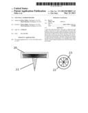
[0008] FIG. 1 is a diagram of a first exemplary embodiment of the invention.
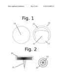
[0009] FIG. 2 is a diagram of a second exemplary embodiment of the invention.
DETAILED DESCRIPTION OF THE INVENTION
[0010] Referring now to the invention in more detail, FIG. 1 shows a disc-type ball marker (10), of the kind well known in the prior art and readily commercially available. The invention may be adapted for use with a specially sized ball marker or for use with one or more standard sizes of commercially available ball markers. Right of the ball marker (10) is the top of a golf club shaft (11) featuring the invention. The top of the shaft (11) has an indented area partially surrounded by a wall or lip (12). Part of the circumference of the lip (12) forms an open section (13) into which the ball marker (10) may be slid. The bottom surface (14) of the indented area is depressible, and is pressed upon from the back by a spring (not shown). Many such spring mechanisms are known in the prior art. When a ball marker (10) is placed inside of the shaft head (11) through the opening (13), the bottom surface (14) is pressed slightly down into the shaft by the ball marker, and the force of the spring on the back of bottom surface (14) holds the ball marker in place.
[0011] Referring now to FIG. 2, the embodiment shown utilizes a ball marker comprising a disc (20) attached to a vertical spike (21) that is pressed into the ground when the ball marker is placed. The top of the club shaft features a circular opening (22) inside of which is a plurality of hinged pie-shaped or triangular members (23) that are under tension (e.g. from a spring, not shown, using any tensioning mechanism of the many known in the prior art) such that they tend to move their tips up and toward the center of the shaft to close the shaft opening (22). When the Ball marker spike (21) is pressed into the plurality of pie-shaped or triangular members (23), the members will exert a force on the spike tending to hold it, and the ball marker, in place on the club shaft.
[0012] The invention may be varied to suit any type of ball marker or golf club shaft. Suitable materials and components for the above-described mechanisms are well known in the prior art.
[0013] While the foregoing written description of the invention enables one of ordinary skill to make and use what is presently considered to be the best mode thereof, those of ordinary skill in the art will understand and appreciate the existence of variations, combinations, and equivalents of the specific embodiment, method, and examples herein. The invention should, therefore, not be limited by the above described embodiment, method, and examples, but by all embodiments and methods within the scope and spirit of the invention.
User Contributions:
Comment about this patent or add new information about this topic:
Images included with this patent application:
 |  |
| Similar patent applications: | |
| Date | Title |
|---|---|
| 2013-12-19 | Golf clubs and golf club heads with adjustable center of gravity and moment of inertia characteristics |
| 2009-12-10 | Golf ball marker |
| 2009-12-10 | Golf ball marker |
| 2010-04-22 | Golf ball marker |
| 2010-05-20 | Golf ball marker |
| New patent applications in this class: | |
| Date | Title |
|---|---|
| 2013-09-12 | Golf putter with marker- and ball-handling features |
| 2013-08-29 | Golf putter attachment to lift golf balls and to prop golf putters |
| 2010-08-12 | Device for securing a golf ball marker to a golf club |
| 2010-05-06 | Multipurpose golf divot tool |
| 2009-05-28 | Golf accessory |
| Top Inventors for class "Games using tangible projectile" | |
| Rank | Inventor's name |
|---|---|
| 1 | Michael J. Sullivan |
| 2 | Brian Comeau |
| 3 | Derek A. Ladd |
| 4 | David A. Bulpett |
| 5 | Mark L. Binette |