Patent application title: SOLAR POWER TOWER SYSTEM
Inventors:
Enrique Serrano Dorado (Madrid, ES)
Ralf Wiesenberg (Rivas Vaciamadrid, ES)
Daniel Rayo Garcia (Leganes, ES)
Héctor Barroso Jimènez (Mostoles, ES)
Héctor Barroso Jimènez (Mostoles, ES)
Héctor Barroso Jimènez (Mostoles, ES)
Javier Villa Briongos (Madrid, ES)
Domingo Santana Santana (Leganes, ES)
Assignees:
UNIVERSIDAD CARLOS III DE MADRID
SUN TO MARKET SOLUTIONS S.L.
IPC8 Class: AF24J204FI
USPC Class:
126646
Class name: Solar heat collector with means to convey fluent medium through collector pump
Publication date: 2013-03-28
Patent application number: 20130074828
Abstract:
A solar power tower system includes a solar tower receiver, a cold
storage tank and a hot storage tank at the bottom of the tower receiver
with a heat transfer fluid down pipe from the receiver and a working
fluid up pipe into the receiver. A potential energy recovery system is
located at the bottom of the tower configured such that it recovers part
of the mechanical energy of the heat transfer fluid and uses it in the
pumping of the working fluid to the receiver and providing power to other
equipment in the solar power tower system in any kind of energy.Claims:
1. A solar power tower system comprising: a solar tower receiver; a cold
storage tank and a hot storage tank at the bottom of the tower receiver
with a heat transfer fluid down pipe from the receiver and a working
fluid up pipe into the receiver; a potential energy recovery system
located at the bottom of the tower configured such that the potential
energy recovery system recovers part of the mechanical energy of the heat
transfer fluid and uses energy recovered in pumping of working fluid to
the receiver or providing power to other equipment in the solar power
tower system.
2. The solar power tower system according to claim 1, wherein the potential energy recovery system comprises: an axial or radial turbine configured to be activated by heat transfer fluid down from the receiver, a pump mechanically joined by a clutch and gears to the turbine configured to pump the working fluid up into the receiver.
3. The solar power tower system according to claim 1, wherein the potential energy recovery system comprises: an axial or radial turbine configured to be activated by heat transfer fluid down from the receiver, a pump mechanically joined by a clutch and gears to the turbine configured to pump the working fluid up into the receiver, a clutch configured to allow the system to couple and uncouple, guaranteeing correct operation in parallel.
4. The solar power tower system according to claim 1, wherein the potential energy recovery system comprises: an axial or radial turbine configured to be activated by the by heat transfer fluid down from the receiver, an electric generator and configured to produce connected to the turbine through a shaft.
5. The solar power tower system according to claim 1, wherein the potential energy recovery system comprises: a piston configured to be activated by heat transfer fluid down from the receiver, a pump mechanically joined by a clutch and gears to the turbine configured to pump the working fluid up into the receiver.
6. The solar power tower system according to claim 1, wherein the potential energy recovery system comprises: a piston configured to be activated by heat transfer fluid down from the receiver, a pump mechanically joined by a clutch and gears to the turbine configured to pump the working fluid up into the receiver. a clutch configured to allow the system to couple and uncouple, guaranteeing correct operation in parallel.
7. The solar power tower system according to claim 1, wherein the potential energy recovery system comprises: a piston configured to be activated by the heat transfer fluid down from the receiver, an electric generator and configured to produce electricity connected to the turbine through a shaft.
8. The solar power tower system according to claim 1, wherein the potential energy recovery system comprises a plurality of pistons located between the down pipe and up pipe configured such that the heat transfer fluid from the down pipe moves the pistons directly transferring its energy to the working fluid which enters into the receiver.
9. The solar power tower system according to claim 1, wherein the potential energy recovery system is a reversible system.
Description:
TECHNICAL FIELD
[0001] This invention is related to power generation systems through the solar energy. Specifically, the invention is applied to solar power tower plants, with cylindrical central receiver configuration or with the cavity receptor configuration.
BACKGROUND
[0002] The growing interest in renewable energies and the increase of the energy demand has produced a strong expansion in the solar electric generation.
[0003] The central receiver concept is based on a field of individually sun-tracking mirrors called heliostats, which reflect the incident solar radiation to a receiver at the top of a centrally located tower (the receiver could be cylindrical or with cavity configuration). This way, the direct radiation is concentrated in the effective area of the receiver allowing it to reach high levels of radiation.
[0004] Any of the receiver configurations is usually positioned at the top of the tower, where it is heated by the reflected radiation from heliostats. The heliostats concentrate and redirect the sun radiation towards the receiver. Typically 80 to 90 percent of the reflected energy is absorbed and transferred to the working fluid, which is pumped up the tower and is also pumped into the receiver. Solar power tower systems usually include a "cold" storage tank and a "hot" storage tank at the bottom of the tower, which provide and collect the fluid that goes through the receiver. This technology also has an energy conversion system, composed of a steam generator and a turbine/generator set.
[0005] The heat transfer fluid can be any medium that has the ability to absorb and transfer the energy as heat properly, such molten salts or high-temperature synthetic thermal oils under 750° C.
[0006] The heat transfer fluid is pumped from the cold tank to the top of the tower, where it circulates inside the receiver. In the receiver outlet, the heat transfer fluid has high mechanical energy, sum of its kinetic energy (originated by the velocity produced by the pumps) and of its potential energy (as a result of its high height at the top of the tower).
[0007] The working fluid is introduced in the hot tank after being introduced through the tower. Due to the high kinetic energy in the inlet, it is necessary to dissipate an important part of the energy to avoid problems and possible damages of performance in the tank storage system. For this reason, a system of plates that produces the necessary pressure drop to eliminate the high energy in the pipe has been traditionally employed.
[0008] The quantity of energy dissipated in the system of pressure drop is an important value which is not recovered. The invention developed in this document shows several alternatives that can recover around the 70 percent of the energy previously dissipated and wasted.
[0009] At the same time, this recovered energy can be employed in the pumping of the fluid to the receiver. This way, the auto-consumption of the plant will be reduced, by improving the performance and the benefits of the plant.
[0010] The approach of this invention and its utility have been developed after having a high understanding and knowledge of the operation of tower power plants.
SUMMARY
[0011] This invention refers to a solar power tower system which comprises a solar tower receiver, a "cold" storage tank and a "hot" storage tank at the bottom of the tower receiver, which recovers part of the mechanical energy of the heat transfer fluid and then it uses this recovered energy in the pumping of the working fluid to the receiver by potential energy recovery system.
[0012] The potential energy recovery system have parallel configuration against the solar power tower and the cold and hot tanks, so that it lets the system to couple or uncouple the solar power tower system operation at any moment, in case of damage of the system or low process profitability under certain circumstances
[0013] On the one hand, for the generic operation of the solar power tower system, a plurality of valves communicate the potential energy recovery system with the rest of the circuit and will be closed, by connecting the potential energy recovery system and closing the complete circuit. On the other hand, when the use of potential energy recovery system is not advantageous, the valves will be opened and the potential energy recovery system will be isolated, so the plant will work as it does nowadays.
[0014] The solar power tower system can comprise a plurality of potential energy recovery systems operating in parallel.
[0015] The potential energy recovery system, is located at the bottom of the tower attached to the hot flow drop pipe and could be located between the receiver and the hot tank, and also between the receiver and the cold tank in more complex configurations. The thermal fluid that circulates through the receiver is located in the most elevated part of the tower, providing a certain potential energy.
[0016] The aim of the potential energy recovery system is to recover all the possible potential energy from the heat transfer fluid.
[0017] The potential energy recovery system could comprise:
[0018] at least one axial or radial turbine or at least a piston that recover potential energy from a fluid to another,
[0019] Additionally it can comprise:
[0020] at least one pump that will propel the cold tank thermal flow to the receiver.
[0021] In this case, the pump is mechanically joined by clutch and gears to a turbine and shall be located relatively close to each other to avoid using excessively complex mechanical transmission systems. A perfect location to perform this mechanical joint or any other might be located where the pipes of hot and cold thermal fluid are divided from each other at the bottom of the tower.
[0022] The potential energy recovery system positioning shall be at the bottom of the tower trying to obtain the most potential energy as possible. This place may be located in a previous point to the discharge of the hot fluid coming from the tower in a tank.
[0023] In case of an electric/magnetic joint, the potential energy recovery system could comprise an electric generator able to transmit the generated mechanical energy from the at least one turbine or at least one piston, to any other component in the solar power tower system.
[0024] In case of a fluid dynamic operation, the potential energy recovery system will comprise a plurality of pistons located between the down pipe and up pipe configured such that the heat transfer fluid from the down pipe (hot pipe) moves the pistons directly transferring its energy to the working fluid (cold pipe) which entries into the receiver. In this case the distance between de hot pipe and the cold pipe will not be a problem because the potential energy recovery system could comprise auxiliary pipes that communicate with them through auxiliary pipes.
[0025] The aim of the potential energy recovery system is to reduce the auto-consumption of the plant with the recovery of potential energy from the thermal fluid due to the great height differences that exist in this kind of technology. Thus, the central efficiency will be higher as a result of the lower consumption of the components. In addition, in case the mechanical joints with the pumps impel the cold tank fluid to the tower, the pumps requirements will decrease and they can be able to operate under lower-demand regimes, this way increasing its lifetime.
BRIEF DESCRIPTION OF THE DRAWINGS
[0026] So that the manner in which the above recited features are attained and can be understood in detail, a more detailed description, which is briefly summarized above, is described below with reference to the Figures illustrated in the appended drawings.
[0027] It is to be noted that the Figures in the appended drawings, like the detailed description, are examples. And as such, the Figures and the detailed description are not to be considered limiting, and other equally effective examples are possible and likely. Furthermore, like reference numerals in the Figures indicate like elements: wherein:
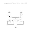
[0028] FIG. 1 is a block diagram depicting an example of a solar power tower system with a potential energy recovery system comprising a turbine and a pump.
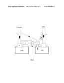
[0029] FIG. 2 is a block diagram depicting an example of a solar power tower system with a potential energy recovery system comprising a turbine and an electric generator
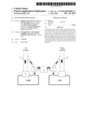
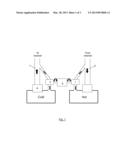
[0030] FIG. 3 is a block diagram depicting an example of a solar power tower system with a potential energy recovery system comprising a plurality of pistons.
DETAILED DESCRIPTION
[0031] In the following detailed description, the embodiments disclosed are for exemplary purposes only and other embodiments may be employed in lieu of or in combination with of the embodiments disclosed
EXAMPLE 1
[0032] FIG. 1 shows a solar power tower system in which the potential energy recovery system is a turbine 1 situated at the bottom of the pipe down 6. This way, the fluid is conducted through an axial or radial turbine 1, extracting the mechanical energy and transforming it in mechanical energy in the shaft of the turbine 1. Pressurized fluid ejected through the turbine blades leaving it with diminished energy. At the same time, this energy will be transmitted through an axis connected to the shaft a pump 2 (could be more than one) that pumps the cold tank into the receiver.
[0033] Furthermore, the transmission shaft will have a clutch 3 which allows the system to couple and uncouple, guaranteeing the correct operation in parallel. It would also have a gear box which can be adapted to the needs.
EXAMPLE 2
[0034] FIG. 2 shows another embodiment of the invention in which the potential energy recovery system comprises:
[0035] an axial or radial turbine 1 connected to the pipe down 6 which extracts the energy contained in the fluid, transforming it in mechanical energy at the exit of the shaft of the turbine 1.
[0036] an electric generator 4 which transfer the energy from the turbine through a shaft which communicates them.
[0037] The generator will produce electricity that can be employed to cover the auto consumption of the several elements 8 that comprise the solar thermal power tower system. It is preferable used as feeding of the pump by sending heat transfer fluid to the top. This way, less loss is obtained due to less transmission losses.
[0038] Optionally, the correct disposition of the elements that compose this configuration will allow inverting the habitual process of operating. This system that, in emergency situations, if any pump fails, the generator could be transformed in motor, producing the necessary mechanical energy to pump from the axial or radial turbine (transformed in motor) feeding the pipe up to the tower.
[0039] The continuous line of FIG. 2 shows the operation of the system generating electricity. This electricity can be injected to the pumps 9 that feed the receiver or any other component feeding with electricity.
[0040] The discontinuous line of FIG. 2 shows the other option discussed above, in which the system is inverted and the turbine 1 and the generator 4 are transformed in pump and motor respectively, allowing the receiver to be fed in emergency situations.
EXAMPLE 3
[0041] FIG. 3 shows another embodiment of the invention in which the potential energy recovery system, which transforms the mechanical energy of the fluid at the outlet of the tower in useful energy for the pumping into the receiver, are a plurality of tubes, valves and pistons 5 configured in order to communicate the two pipes 6, 7 of the tower so that is directly the hot fluid the one which transfers its energy to the cold fluid which entries to the tower receiver.
[0042] This way, through the natural tendency to equalize the pressure at both sides of the pistons, the cold fluid will be pumped into the receiver because of the high pressure of the hot fluid at the exit of the tower. For example, in the simplest configuration, both fluids must be in the same tube, only separated by a piston, which will equilibrate the pressures.
[0043] To guarantee the continuity in the pumping, it will be necessary to get some parallel systems, which produce a uniform flow.
User Contributions:
Comment about this patent or add new information about this topic:
Images included with this patent application:
 |  |
 |  |
| Similar patent applications: | |
| Date | Title |
|---|---|
| 2009-01-01 | Solar power harvester |
| 2010-09-23 | Solar roofing system |
| 2010-09-23 | Solar roofing system |
| 2011-07-14 | Solar trough field system |
| 2012-04-12 | Solar thermal system |
| New patent applications in this class: | |
| Date | Title |
|---|---|
| 2016-06-16 | Circulating pump unit and solar thermal plant |
| 2015-12-31 | All-polymer flat plate heating solar panel with integrated controller |
| 2015-05-21 | Solar thermal panel array field arrangement and related vacuum solar thermal panel |
| 2013-08-08 | Molten salt solar receiver and procedure to reduce the temperature gradient in said receiver |
| 2013-03-28 | Apparatus and method for solar energy collection and conversion |
| Top Inventors for class "Stoves and furnaces" | |
| Rank | Inventor's name |
|---|---|
| 1 | Paul Bryan Cadima |
| 2 | David Deng |
| 3 | Andrew Plotkin |
| 4 | Peter Emery Von Behrens |
| 5 | Derek W. Schrock |