Patent application title: ACEnergySaver (AC Energy Saver)
Inventors:
Richard D. Townsend (Barrington, NH, US)
IPC8 Class: AF24J308FI
USPC Class:
165 45
Class name: Heat exchange geographical
Publication date: 2013-02-21
Patent application number: 20130042995
Abstract:
The ACEnergySaver is a system that consisting of a low-voltage
water-controlling solenoid, tubing, fittings, wire-harness and
spray-nozzles to easily, properly and effectively: a) attached to an air
conditioner; b) control and regulate specific quantity, angle and size of
water particles (spray) to the cooling fins/coil; c) connect to a water
supply. It extends equipment longevity and saves electricity by causing:
a) evaporative cooling, b) rapid coolant conversion from liquid to gas,
c) reduced pressure resistance the compressor to cool faster and optimize
efficiency. Pressurized supply-water enters a solenoid valve, connected
to the low-voltage terminal(s) of the joined air conditioner's relay to
open simultaneously with the compressor to pass 4water onto the
cooling fins through the system.Claims:
1. The ACEnergySaver Saves electricity and extends the longevity of air
conditioners and heat pumps: a) By example of geothermal energy,
transference, "GeoExchange" (US Department of Energy) and evaporation,
applying water to cooling fins of an air conditioner removes heat, mainly
by evaporation and causes rapid transference of liquid coolant to a gas,
reducing the pressure and energy to compress (i.e. operate) coolant.
Similarly, the application is used to save energy during heating in heat
pump applications. b) is achieved by this invention by applying ground
temperature (lower than air temperature for cooling and higher than air
temperature for heating) at and within specific parameters to optimize
efficiency, save energy and prolong longevity of mechanical devices. c)
is achieved by integrating an electrical magnetic control valve
(solenoid) with a thermal coupler to intercept continuity during
non-conducive temperatures. The valve contains a high-pressure inlet and
open flow outlet with volume control to spray nozzles designed specific
to this application. d) This invention is unique in that the solenoid,
all connections, spray nozzles, control module box and electric
components have been engineered and designed specifically for the
application.Description:
BRIEF DESCRIPTION
[0001] Device: The ACEnergySaver is a product consisting of control mechanisms and hardware to automatically apply water to the fins of an air conditioner.
[0002] Purpose: Save energy, prevent electrical shortage brown outs, extend the longevity of air conditioners, reduce landfilling, reduce pollutants.
SPECIFICATIONS
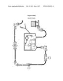
[0003] The ACEnergySaver is designed with 9 new, unique components and subcomponents, per drawings: 0001, 0002-A, 0002-B, 0003, 0003-A, 0003-B, 0004, 0005, 0006, 0007, integrated to create a new use and product, shown complete in diagram
[0008].
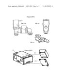
[0004] Solenoid is specifically designed for both use and efficient installation and to be integrated into a Control Module Box (CMB)
[0002].
[0005] 24 volts AC coil windings are used in its designed to withstand greater temperatures and longer, near constant duty cycles than operating conditions.
[0006] Inlet and outlet quick connect water tubing ports
[0007] Flow restrictor is sized to permit a manual magnet to open the valve with no electricity and while within typical potable water pressure range.
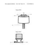
[0008] ("CMB") Control Module Box (2A) and cover (2B) is an integrated design to enclose, secure, vent and protect the solenoid
[0001] and thermal couple (FIG. 3-A). A molded bushing (2-C) extrusion from the back of the CMB (2-A) passes through the air conditioner housing to separate and protect wires from chafing and secures the CMB with the use of only one mounting screw.
[0009] Wire harness consists of 3 wires with female terminal connectors on all ends, integrating solenoid
[0001] through intercepting Thermal Couple (FIG. 3-A) (closed when temperature is above 50F (10C)) to the low voltage thermostat-controlled power source in the air conditioner. M X Ground (FIG. 3-B) allows one female terminal to be grounded when used with a single 24-volt relay terminal. When the air conditioner relay provides 12 volts on 2 separate terminals, the M X Ground terminal is simply removed, hence most efficient and universal.
[0010] Spray Nozzles (described herein) are designed with a fine tolerance, to
[0011] direct a near parallel spray pattern to the air conditioner cooling fins,
[0012] create and manage the best water volume and particle size, necessary to optimally function in various conditions such as wind and fan turbulence and use with all types of protective louvers that would otherwise obstruct or misdirect efficient and effective direct spray contact.
[0013] Hose bib adapter is used to attach tubing to a water port of a structure that is referred to as a "hose bib" or "sill cock" or such likeness as a "boiler drain". This unique design adds a 90-degree angle tubular outlet stem (5-A) and a solid stem (5-B) of which the tubing with a 90-degree elbow connector, can be safely stowed.
[0014] T X F10-32 Female: Tubing Ports (6-B) receives tubing and delivers water through a threaded tubular stem (6-A) where the male portion of the spray nozzle is connected. Ears (6-C) stabilize the critical angle-position for spray pattern.
[0015] Elbow Valve with Ear: Eliminates the need for several parts and serves to secure the tubing tightly in quick fit ports (7-B), adjust water flow with thumbscrew (7-A) and stretch and secure all tubing and fittings with a screw in the ear (7-C).
[0016] Standard components:
[0017] 90-degree tubing elbows
[0018] self-drilling screws
[0019] tubing that delivers water from the Hose Bib Adapter
[0005] to and controlled by the Solenoid
[0001] through the Elbow Valve
[0007], through the T X 10-32
[0006], and out of the Spray nozzles
[0004].
OPERATION
[0020] Water is provided from existing hose bib or plumbing that serves a structure such as home or business and through the system called ACEnergySaver. This product controls water wetting the fins of an air conditioner when activated by a thermostat. A thermocouple allows the ACEnergySaver to assist heating and cooling via a geothermal-like exchange above 50F. (10C). Although designed primarily to assist cooling, it also assists heating when heat exchange systems are used.
Evolution
[0021] of this product and supporting tests that makes this application unique and viable:
[0022] Beginning with a manual application, we connected a hose to a home water supply and manually sprayed water onto the cooling fins of a central air conditioner using readily available misting and spray nozzles.
[0023] A variety of nozzles were required to meet the various physical characteristics of the air conditioner. We designed and modified a unique nozzle to meet all conditions with minimal water consumption, a good size water particle, and more importantly, a spray pattern that is closer to parallel angle with the surface of an air conditioner to be drawn into the fins evenly with the air conditioner fan. We found this to be the most complicated and critical phase of the invention.
[0024] The best wetting application we discovered during testing was derived from a small 360-degree fine spray located 2/3rd up from the bottom of the cooling fins, adjusted by an in-line valve. The distance of spray reduced by the valve became lighter to enable drawing most or all of the downward spray. Water consumption is negligible. Because all nozzles that disburse a viable size water particle direct away from a horizontal plane (parallel to the air conditioner fins), we found that we could redesign the angle and orifice size to minimize or eliminate excess water. No existing spray nozzles would provide a viable application, especially a fine fogging mist as they would draw too quickly and pass between the fins, missing essential contact in order to provide evaporation. Wind and condition turbulence posed a drastic negative effect that essentially displaced the particles away from the application entirely.
[0025] Automation by solenoid (and thermal couple) was the favored conclusion because we could utilize proven solenoids (similar to washing machine, ice and coffee maker devices) that perform similarly and consistently reliable for many years, modified to fit our application. Other tested manual or mechanical devices (such as toilet float valves) require excessive expense. The in and out tube ports were engineered at the bottom of the box to improve appearance, fitting and tubing positioning, cost and easier installation.
[0026] Adding a thermal coupler eliminated electrical field cycles when temperatures are below optimal conditions. We discovered that this product additionally works with the heating cycle of heat pumps by introducing ground temperature from which heat is extracted, while the thermal couple will not permit it to operate when ice could form. This also eliminates a need for an electrical switch or manually disconnecting the electrical connection when winterizing is required.
[0027] During various installations, we were able to achieve the most efficient labor savings by redesigning the fittings that would incorporate all tedious labor requirements. Designing fittings that contain eyelets eliminated the need for clamps; utilizing quick connects eliminated hard pressing of tubing which became more important when we upgraded to a high quality heavy walled tubing; combining the manual valve into a 90 degree elbow with an eyelet eliminated several extra parts and secures the beginning and end of the tube that stretches horizontally around the air conditioner. It also adds a drain end in place of an end cap (plug) as an alternative in freezing climates. The hose bib adapter now has a solid "hangar" to stow the tubing at the hose bib when winterized, eliminating parts. These progressions substantially contribute to reducing assembly labor.
[0028] Once we redesigned and incorporated all of the components, we were able to redesign the plastic housing to the smallest size, easiest installation and best appearance.
CONCLUSION
[0029] The ACEnergySaver simulates geothermal heating and cooling exchange systems with minimal cost and is viable in all applications. Geothermal systems require wells, ground area or special drainage conditions. This product works in all applications because the water it uses evaporates (water into a gas), requires no space, is thousands of dollars less than a geothermal system while performing similarly, will adapt to all of millions of existing air conditioners in use, provides alternatives to new construction and saves our environment in numerous ways. This product could be the largest contributor to our current energy concerns.
BRIEF SUMMARY OF THE INVENTION
[0030] The ACEnergySaver saves energy by about 30 to 60% and reduces wear and landfilling proportionately. The estimated cost to apply water is currently about $3.50 per year. The product is projected to pay for itself in about 2 to 3 months. The funds to purchase labor and materials come from energy savings, so we can conclude that this product will contribute to stimulating the economic recovery.
BRIEF DESCRIPTION OF SEVERAL VIEWS OF THE DRAWINGS
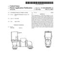
[0031] Solenoid: low voltage water valve
[0032] FIG. 1-A: Side view
[0033] FIG. 1-B.: End view
[0034] FIG. 1-C: Angle view
[0035] Control Module Box (CMB): is a designed enclosure to house, secure and protect the solenoid, thermal couple and wire connections
[0036] 2-A: CMB Box
[0037] 2-B: CMB Cover
[0038] 2-C: Bushing extrusion
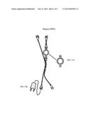
[0039] Wire harness: 3 wires with female terminal connectors on all ends, one with a Male X GROUND terminal insert and a THERMAL COUPLE
[0040] FIG. 3-A: Thermal couple
[0041] FIG. 3-B: Male X Ground terminal connector
[0042] Spray Nozzle
[0043] 4-A: Crosscut section shows spray direction from
[0044] 4-B: Orifice with 2 drawn arrows
[0045] 4-C: 10-32 Thread on tubular section
[0046] Hose Bib Adapter: Connects tubing to typical hose bib faucet
[0047] 5-A: Tubular stem
[0048] 5-B: Solid stem
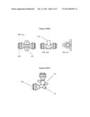
[0049] T×F10-32 w/ears: A quick push tubing and spray nozzle connector
[0050] FIG. 6-A: Top view
[0051] FIG. 6-B: Side view
[0052] FIG. 6-C: End view
[0053] 6-A: 10-32 Female threaded port
[0054] 6-B: Tubing port contains collets and O-ring
[0055] 6-C: Ear
[0056] Elbow Valve with Ear:
[0057] 7-A: Valve Adjustment
[0058] 7-B: Tubing ports contains collets and O-ring
[0059] 7-C: Ear
[0060] Assembled diagram for the "Front page view" per 37 CFR 1.84 (5)(j)
User Contributions:
Comment about this patent or add new information about this topic:
Images included with this patent application:
 |  |
 |  |
 |  |
| Similar patent applications: | |
| Date | Title |
|---|---|
| 2014-03-06 | Inlet air chilling system with humidity control and energy recovery |
| 2014-03-06 | Beverage container sleeve and method of making and using same |
| 2014-03-06 | Thermal energy storage vessel, systems, and methods |
| 2014-03-06 | Plate-type heat exchanger and support structure thereof |
| New patent applications in this class: | |
| Date | Title |
|---|---|
| 2022-05-05 | Medium-deep non-interference geothermal heating system and method based on loose siltstone geology |
| 2019-05-16 | Method of deploying a heat exchanger pipe |
| 2016-12-29 | High efficiency heating and/or cooling system and methods |
| 2016-06-30 | Geothermal energy collection system |
| 2016-05-26 | Trench-conformable geothermal heat exchange reservoirs and related methods and systems |
| Top Inventors for class "Heat exchange" | |
| Rank | Inventor's name |
|---|---|
| 1 | Levi A. Campbell |
| 2 | Chun-Chi Chen |
| 3 | Tai-Her Yang |
| 4 | Robert E. Simons |
| 5 | Richard C. Chu |