Patent application title: PSEUDONOISE GENERATION DEVICE AND PSEUDONOISE GENERATION METHODAANM Asao; KojiAACI Kawagoe-shiAACO JPAAGP Asao; Koji Kawagoe-shi JPAANM Tanaka; JunichiAACI Kawagoe-shiAACO JPAAGP Tanaka; Junichi Kawagoe-shi JP
Inventors:
Koji Asao (Kawagoe-Shi, JP)
Junichi Tanaka (Kawagoe-Shi, JP)
Assignees:
PIONEER CORPORATION
IPC8 Class: AH04B100FI
USPC Class:
381 86
Class name: Electrical audio signal processing systems and devices vehicle
Publication date: 2013-01-17
Patent application number: 20130016851
Abstract:
A determination part specifies the road width upon which the vehicle CR
is traveling based on the current position of a vehicle CR detected by a
position detection part, referring to road width information in a storage
part. The part determines an arrival ranges for pseudonoise being
outputted outside the vehicle based on the specified road width.
Subsequently, a control part determines audio volume settings for
pseudonoise from left and right speakers of a pseudonoise generation
part, based on the determined arrival range. As a result, pseudonoise at
audio volumes corresponding to the audio volume settings is outputted
outside the vehicle from the speakers of the part. Thus, the output of
the pseudo engine noise is properly controlled with in consideration for
the presence of the possible subject to be warned in a variety of
surroundings changed depending on the classification of the road.Claims:
1. A pseudonoise generation device that is mounted to a vehicle and
outputs pseudonoise from a sound output part to the outside of said
vehicle comprising: a storage part configured to store map information
that includes road width information; a position detection part
configured to detect the current position of said vehicle; a
determination part configured to determine a pseudonoise arrival range
over which pseudonoise outputted from said sound output part is to
arrive, on the basis of road width information for the road upon which
said vehicle is traveling; and a control part configured to control the
output of pseudonoise from said sound output part to correspond to said
range that has been determined.
2. A pseudonoise generation device according to claim 1, wherein: said determination part determines said pseudonoise arrival range to be a first predetermined range, symmetrically against a running direction of said vehicle, when the width of the road upon which said vehicle is traveling is not larger than the first threshold value; and said determination part determines said pseudonoise arrival range to be broader on a side wherein a pedestrian may be present against the traveling direction of said vehicle than said first predetermined range, when the width of the road upon which said vehicle is traveling is wider than said first threshold value.
3. A pseudonoise generation device according to claim 1, wherein said determination part determines said pseudonoise arrival range to be minimal on an opposite lane side against said traveling direction of said vehicle, when the width of the road upon which said vehicle is traveling is greater than said first threshold value, and an assumed opposite vehicle lane is present.
4. A pseudonoise generation device according to claim 1 further comprising: an acquisition part that acquires traveling information for said vehicle, including the traveling direction of said vehicle; and a calculation part that calculates the running distance in said acquired traveling direction along said road upon which said vehicle is traveling to an intersection with another road, on the basis of said detected current position and said map information; wherein said determination part determines said pseudonoise arrival range with further for the calculation result.
5. A pseudonoise generation device according to claim 4, wherein said determination part sets a predetermined distance for the running distance along the road upon which said vehicle is traveling to said intersection; wherein the running distance to said calculated intersection is not larger than said predetermined distance; said determination part determines a range broader in the traveling direction of said vehicle and to the left side than said pseudonoise arrival range of said first predetermined range, when said other road extends only to the left side; said determination part determines a range broader in the traveling direction of said vehicle and to the right side than said pseudonoise arrival range of said first predetermined range, when said other road extends only to the right side; and said determination part determines a range symmetric in the traveling direction of said vehicle and broader than said pseudonoise arrival range of said first predetermined range, when said other road extends only to the left side.
6. A pseudonoise generation device according to claim 4, wherein, said determination part determines said range to be a second predetermined range to be minimum, when the width of the road upon which said vehicle is traveling is wider than a second threshold value, and said calculated running distance to said intersection is not less than said predetermined distance.
7. A pseudonoise generation device according to claim 4, wherein, said determination part narrows said pseudonoise arrival range as the vehicle is close to said intersection, when the running distance to said intersection is not larger than said predetermined distance.
8. A pseudonoise generation device according to claim 4, wherein: said traveling information includes a vehicle speed; and said determination part expands said pseudonoise arrival range as the acquired vehicle speed is high.
9. A pseudonoise generation method employed by a pseudonoise generation device for outputting pseudonoise from a sound output part to the outside of a vehicle, comprising the steps of: an acquisition step for acquiring road width information for the road upon which said vehicle is traveling; a determination step for determining a pseudonoise arrival range over which pseudonoise outputted from said sound output part should arrive, on the basis of said acquired road width information; and a control step for controlling the output of pseudonoise from said sound output part to correspond to said determined range.
10. A pseudonoise generation program, wherein a pseudonoise generation method according to claim 9 is executed by a calculation part.
11. A recording medium, wherein a pseudonoise generation program according to claim 10 is stored in a readable format by a calculation part.
12. A pseudonoise generation device according to claim 2 further comprising: an acquisition part that acquires traveling information for said vehicle, including the traveling direction of said vehicle; and a calculation part that calculates the running distance in said acquired traveling direction along said road upon which said vehicle is traveling to an intersection with another road, on the basis of said detected current position and said map information; wherein said determination part determines said pseudonoise arrival range with further for the calculation result.
13. A pseudonoise generation device according to claim 3 further comprising: an acquisition part that acquires traveling information for said vehicle, including the traveling direction of said vehicle; and a calculation part that calculates the running distance in said acquired traveling direction along said road upon which said vehicle is traveling to an intersection with another road, on the basis of said detected current position and said map information; wherein said determination part determines said pseudonoise arrival range with further for the calculation result.
14. A pseudonoise generation device according to claim 5, wherein, said determination part determines said range to be a second predetermined range to be minimum, when the width of the road upon which said vehicle is traveling is wider than a second threshold value, and said calculated running distance to said intersection is not less than said predetermined distance.
15. A pseudonoise generation device according to claim 5, wherein, said determination part narrows said pseudonoise arrival range as the vehicle is close to said intersection, when the running distance to said intersection is not larger than said predetermined distance.
16. A pseudonoise generation device according to claim 6, wherein, said determination part narrows said pseudonoise arrival range as the vehicle is close to said intersection, when the running distance to said intersection is not larger than said predetermined distance.
17. A pseudonoise generation device according to claim 5, wherein: said traveling information includes a vehicle speed; and said determination part expands said pseudonoise arrival range as the acquired vehicle speed is high.
18. A pseudonoise generation device according to claim 6, wherein: said traveling information includes a vehicle speed; and said determination part expands said pseudonoise arrival range as the acquired vehicle speed is high.
19. A pseudonoise generation device according to claim 7, wherein: said traveling information includes a vehicle speed; and said determination part expands said pseudonoise arrival range as the acquired vehicle speed is high.
20. A pseudonoise generation device according to claim 12, wherein, said determination part determines said range to be a second predetermined range to be minimum, when the width of the road upon which said vehicle is traveling is wider than a second threshold value, and said calculated running distance to said intersection is not less than said predetermined distance.
Description:
TECHNICAL FIELD
[0001] The present invention relates to a pseudonoise generation device, a pseudonoise generation method, a generation program for pseudonoise, and a recording medium in which the generation program is stored.
BACKGROUND ART
[0002] In recent years, electric automobiles employing batteries as a drive power source and hybrid cars employ the batteries as partial drive power source have become popular. When such an automobile uses the battery as the drive power source to drive, the drive noise level outside of the vehicle becomes dramatically lower as compared to those from a conventional gasoline vehicle. As a result, it may happen that a pedestrian or a cyclist does not notice a vehicle approaching to them from outside his field of view. The occurrence of the situation is a serious traffic safety problem.
[0003] Due to this, a technique has been proposed for outputting a running noise corresponding to the running condition of the vehicle outside the vehicle (see Patent Document #1, hereinafter, it is referred to as "prior art #1"). In the technique of the prior art #1, the running noise is output outside the vehicle ahead or the like through a speaker for generating a pseudonoise signal based on the detection results of the vehicle speed, the rotational speed of the motor as the power source, the accelerator position, and so on. Then, it is controlled whether the traveling sound is output or not, depending on a region type through which the vehicle is traveling.
[0004] Moreover, a technique has been proposed (see Patent Document #2, hereinafter called the "prior art #2") for automatically warning a pedestrian existing ahead in a traveling direction of the vehicle, although it is not the technique for outputting a engine pseudonoise corresponds to the running condition of the vehicle or the like. In the technique of the prior art #2, a subject presents ahead in the traveling direction of the vehicle are detected. If the subject is detected, the subject is warned by using a warning sound outputted from the speaker.
PRIOR ART DOCUMENTS
Patent Literature
[0005] Patent Document #1: Japanese Laid--Open Patent Publication 2005-253236 [0006] Patent Document #2: Japanese Laid--Open Patent Publication Heisei 7-209424
SUMMARY OF THE INVENTION
Problems to be Solved by the Invention
[0007] The technique of the prior art #1 controls the execution/non-execution of pseudonoise output, depending on the region type through which the vehicle is traveling. However, it does not control the pseudonoise output in consideration of the road condition upon which the vehicle is traveling. As a result, if the region type is the same, it cannot control the running noise output with consideration for the probable presence of the pedestrian or the cyclist or the like around the vehicle.
[0008] Moreover, the technique of the prior art #2 outputs the warning sound only in cases which the subject exists ahead in the traveling direction is detected. As a result, for example, the vehicle approach cannot be warned, when the pedestrian, the cyclist or the like cannot be detected because they are hidden by a building or the like.
[0009] Due to this, the technique is eagerly awaited for properly alerting the pedestrian, the cyclist or the like to the approach of the vehicle, even if they cannot be detected by the vehicle. It is raised as one of the problems to be solved by the present invention for responding a request.
[0010] The present invention has been completed under the above-mentioned circumstances. Its object is to provide a pseudonoise generation device and a method for generating pseudonoise, wherein the pseudonoise is properly controlled, considering to the probability of the subject to be warned, which changes depending on the lane class upon which the vehicle is traveling.
Means for Solving the Problems
[0011] When viewed from a first standpoint, the present invention is a pseudonoise generation device that is mounted to a vehicle and outputs pseudonoise from a sound output unit to the outside of said vehicle, characterized by comprising: a storage unit in which is stored map information that includes road width information; a position detection unit that detects the current position of said vehicle; a determination unit that determines a pseudonoise arrival range over which pseudonoise outputted from said sound output unit is to arrive, on the basis of road width information for the road upon which said vehicle is traveling; and a control unit that controls the output of pseudonoise from said sound output unit to correspond to said range that has been determined.
[0012] And, when viewed from a second standpoint, the present invention is a pseudonoise generation method employed by a pseudonoise generation device that outputs pseudonoise from a sound output unit to the outside of a vehicle, characterized by comprising: an acquisition process of acquiring road width information for the road upon which said vehicle is traveling; a determination process of determining a pseudonoise arrival range over which pseudonoise outputted from said sound output unit should arrive, on the basis of said acquired road width information; and a control process of controlling the output of pseudonoise from said sound output unit to correspond to said range that has been determined.
[0013] Moreover, when viewed from the third standpoint, the present invention is a generation program for vehicle-evocative sound, wherein it causes a calculation part to execute a generation method for vehicle-evocative sound according to the present invention.
[0014] Furthermore, when viewed from the fourth standpoint, the present invention is a recording medium, wherein a generation program for vehicle-evocative sound according to the present invention is recorded thereon so as to be readable by a calculation part.
BRIEF DESCRIPTION OF THE DRAWINGS
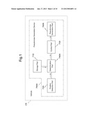
[0015] FIG. 1 is a block diagram for explaining the configuration of a generation device for pseudonoise of the first embodiment of the present invention;
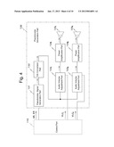
[0016] FIG. 2 is the block diagram for explaining the configuration of a pseudonoise generation device according to the second embodiment of the present invention;
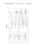
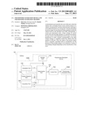
[0017] FIG. 3 is the block diagram for explaining the configuration of a navigation device according to an embodiment of the present invention;
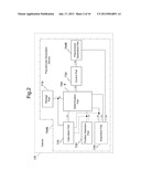
[0018] FIG. 4 is a figure for explaining the configuration of a pseudonoise generation unit of FIG. 3;
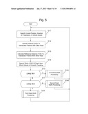
[0019] FIG. 5 is a flow chart for explaining a pseudonoise generation control processing performed by a control unit of FIG. 3;
[0020] FIG. 6 is the flow chart for explaining the first road width processing of FIG. 5;
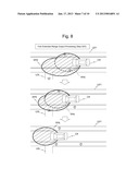
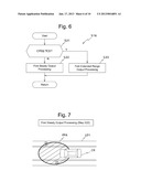
[0021] FIG. 7 is the figure for explaining an arrival range for engine pseudonoise due to first normal output processing of FIG. 6;
[0022] FIG. 8 is the figure for explaining an arrival range for engine pseudonoise due to first extended range output processing of FIG. 6;
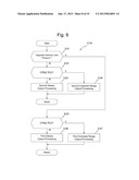
[0023] FIG. 9 is the flow chart for explaining second road width processing of FIG. 5;
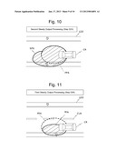
[0024] FIG. 10 is the figure for explaining an arrival range for engine pseudonoise due to second normal output processing of FIG. 9;
[0025] FIG. 11 is the figure for explaining an arrival range for engine pseudonoise due to third normal output processing of FIG. 9;
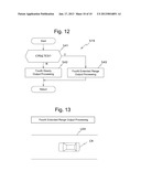
[0026] FIG. 12 is the flow chart for explaining third road width processing of FIG. 5; and
[0027] FIG. 13 is the figure for explaining an arrival range for engine pseudonoise due to fourth normal output processing of FIG. 12.
DESCRIPTION OF THE PREFERRED EMBODIMENTS
[0028] Embodiments of the present invention are explained with reference to the appended drawings. Note that the same or equivalent elements are given the same reference symbols to omit the duplication in the explanation and drawings in below.
The First Embodiment
[0029] First, the first embodiment of the present invention is explained with reference to FIG. 1.
<Configuration>
[0030] FIG. 1 shows the schematic configuration of a pseudonoise generation device 700A of the first embodiment. As shown in FIG. 1, the pseudonoise generation device 700A is mounted to a vehicle CR.
[0031] The pseudonoise generation device 700A comprises a storage part 710 and a position detection part 720. Moreover, the pseudonoise generation device 700A comprises a determination part 740, a control part 750, and a pseudonoise generation part 760A.
[0032] A variety of information utilized by the device 700A is stored in the part 710. The information comprises map information. The map information includes road width information and the information opposite lane presence information.
[0033] The position detection part 720 detects the current position of the vehicle CR. The current position detected by the position detection part 720 is sent to the determination part 740A.
[0034] The determination part 740A receives the current position of the vehicle CR sent from the position detection part 720. The determination part 740A determines ranges over which pseudonoise being outputted to the outside of the vehicle by the pseudonoise generation part 760A should arrive (hereinafter, it is referred to as simply the "arrival ranges") on the basis of the current position, referring to the map information in the storage part 710. The determined arrival ranges for pseudonoise are sent to the control part 750. Note that the determination processing by the determination part 740A is described hereinafter.
[0035] The control part 750 receives the arrival ranges from the determination part 740A. The control part 750 sends audio volume settings necessary for ensuring the arrival ranges to the sound output part 760A.
[0036] The pseudonoise generation part 760A comprises a pseudonoise signal generation part, an audio volume adjustment part, and one or more speakers. In the first embodiment, the pseudonoise generation part 760A includes two speakers: a left speaker for outputting the sound ahead of the vehicle CR on the left, and a right speaker for outputting the sound ahead of it on the right. Note that the control part 750 provides mutually independent volume settings for each of the left and the right speakers.
[0037] The pseudonoise generation part 760A receives audio volume settings from the control part 750. In the pseudonoise generation part 760A, the audio volume adjustment part adjusts the pseudonoise signals generated by the pseudonoise signal generation part 760A according to the audio volume settings, and thereby pseudonoise is outputted outside the vehicle CR from the speakers.
<Operation>
[0038] Next, the operation of the pseudonoise generation device 700A having the configuration is explained. Note that the position detection part 720 detects the current position of the vehicle CR to send periodically it to the determination part 740A.
[0039] Upon receipt of the current position of the vehicle CR, the determination part 740A specifies the road width upon which the vehicle CR is currently traveling on the basis of the current position, referring to the map information in the storage part 710. Subsequently, the determination part 740A decides the first threshold value decision whether the specified road width is not larger than the first threshold value. Here, the "first threshold value" is determined in advance on the basis of investigation, experience and so on, from the standpoint such that it is difficult for the vehicles to passe one another and the pedestrians or bicycles can be passing on both sides of the road.
[0040] If the first threshold value decision result is affirmative, the determination part 740A determines the first predetermined range, which has symmetrical range to the traveling direction of the vehicle MV, as the arrival range. Here, the "first predetermined range" is determined in advance on the basis of investigation, experience and so on, from the standpoint for alerting the attention of the approach of the vehicle to the pedestrian or bicycle on either side of a road of which is not larger than the predetermined threshold value.
[0041] If the first threshold value decision result is negative, if the road width decision result is negative, the determination part 740 decides whether the vehicle is traveling on the road supposed to have the opposite vehicle lane, referring to the map information in the storage part 710 on the basis of the current position. If the opposite vehicle lane decision result is negative, the determination part 740 determines the broader range for the side, on which the pedestrian or the like may be present (hereinafter, it is referred to as the "pedestrian side"), than the first predetermined range as the pseudonoise arrival range (hereinafter, it is referred to as a "pedestrian side expanded range"). The side means the left side in a country where drivers keep to the right side of the road under a law, and the right side in the country where drivers keep to the right side of the road under the law. On the other hand, if the opposite vehicle lane decision result is affirmative, the determination part 740A determines a range, of which becomes minimal on the opposite vehicle lane side against the traveling direction of the vehicle CR as the arrival range; namely, the side where no pedestrian or the like is present.
[0042] When the arrival ranges is thus determined, the determination part 740 sends the determined arrival range to the control part 750. Upon receipt of the arrival range, the control part 750 calculates the audio volumes to be set.
[0043] Here, the control part 750 calculates the first audio volume setting as the audio volume setting for both the left and the right speakers, when the arrival range is the predetermined range. Note that the "first audio volume setting" is determined in advance on the basis of experiment, simulation, experience and so on, from the standpoint that it arrives inside the first predetermined range.
[0044] Furthermore, the control part 750 calculates louder audio volume setting than the first audio volume setting as the audio volume setting for the speaker on the pedestrian side, when the pedestrian side range is the pedestrian side expanded range. On the other hand, the control part 750 calculates the first audio volume setting as the audio volume setting for the other speaker.
[0045] Moreover, the control part 750 sets the audio volume setting for the speaker on the opposite vehicle lane side to 0, when the pedestrian side range is minimal. On the other hand, the control part 750 calculates the first audio volume setting as the audio volume setting for the other speaker.
[0046] Note that, in the first embodiment, the control part 750 makes the audio volume setting for the speaker on the pedestrian side louder, depending on the road width upon which the vehicle is traveling, referring to the road width information in the storage part 710.
[0047] When the audio volume settings have been thus calculated, the control part 750 sends the calculated audio volume settings to the pseudonoise generation part 760A. Upon receipt of the audio volume setting, the pseudonoise generation part 760A outputs pseudonoises to the outside of the vehicle CR from the speakers, adjusting the audio volumes thereof according to the audio volume setting.
[0048] As explained above, in the first embodiment, the determination part 740A specifies the road width, upon which road the vehicle CR is traveling, on the basis of the current position of the vehicle CR as detected by the position detection part 720, referring to the road width information in the storage part 710. The determination part 740A determines the arrival ranges for the pseudonoise being outputted to the outside of the vehicle on the basis of the specified road width. Subsequently, the control part 750 calculates audio volume settings for the pseudonoises being outputted from the left and right speakers of the sound output part 760A, on the basis of the determined arrival ranges. As a result, the pseudonoises having audio volumes corresponding to the audio volume settings are outputted to the outside of the vehicle from the left and right speakers of the pseudonoise generation part 760A.
[0049] Therefore, in the first embodiment, according to the first embodiment, the output of the pseudonoise during traveling is controlled, considering the possibility for the existence of the subject in the circumstances that change depending on the classes of the road.
[0050] Moreover, in the first embodiment, if the specified road width is not larger than the first predetermined value, the determination part 740 determines the arrival ranges as the predetermined range having symmetrical range against the traveling direction of the vehicle CR. Furthermore, if the specified road width is wider than the first predetermined value without opposite vehicle lane, the determination part 740 determines the range, which is broader in the side where the pedestrian or the like is highly possible to be present nearby against the traveling direction of the vehicle CR than the first predetermined range. Yet further, if the specified road width is wider than the first threshold value with the opposite vehicle lane, the determination part 740 determines the range, of which area is minimal, as the arrival range on the opposite vehicle lane side against the traveling direction of the vehicle CR, namely, the side where no pedestrian or the like is present.
[0051] Due to this, in the first embodiment, the pseudonoise may be output at a reasonable output audio volume, considering the presence of the subject to be alerted.
The Second Embodiment
[0052] Next, the second embodiment of the present invention is explained with reference to FIG. 2.
<Configuration>
[0053] FIG. 2 shows the schematic configuration of a pseudonoise generation device 700B of the second embodiment. As shown in FIG. 2, the pseudonoise generation device 700B is mounted to a vehicle CR as the same as the pseudonoise generation device 700A.
[0054] As compared to the pseudonoise generation device 700A, the pseudonoise generation device 700B different in the features therein it comprises a determination part 740B instead of 740A, a pseudonoise generation part 760B instead of 760A, and additionally an acquisition part 730 and a calculation part 735. In the following, the configuration is explained principally focusing on the feature.
[0055] Note that, in the second embodiment, the position detection part 720 detects the current position to send it to the calculation part 735 and to the determination part 740B.
[0056] The acquisition part 730 acquires the traveling direction of the vehicle CR. The traveling direction acquired by the acquisition part 730 is sent to the calculation part 735 and to the determination part 740B.
[0057] Moreover, the acquisition part 730 acquires the vehicle speed detected by a vehicle speed sensor fitted to the vehicle CR. The acquired vehicle speed information by the acquisition part 730 is sent to the determination part 740B.
[0058] Moreover, among a variety of physical quantities detected by other sensors fitted to the vehicle CR, the acquisition part 730 acquires accelerator information such as the accelerator pedal depressed amount and so on and rotational speed information for the motor and so on. The acquired accelerator information and the rotational speed information by the acquisition part 730 are sent to the pseudonoise generation part 760B.
[0059] The calculation part 735 receives the current position of the vehicle CR sent from the position detection part 720 and the traveling direction of the vehicle CR sent from the acquisition part 730. The calculation part 735 calculates the running distance from the current position to the intersection, at which the road upon which the vehicle CR is traveling and some other road intersect (hereinafter, it is referred to as the "calculated distance"), referring to the map information in the storage part 710 on the basis of the current position and the traveling direction. The calculated distance is sent to the determination part 740B.
[0060] The determination part 740B receives the current position of the vehicle CR sent from the position detection part 720, the traveling direction and the vehicle speed information sent from the acquisition part 730, and the calculated distance sent from the calculation part 735. The determination part 740B determines the arrival range for pseudonoise being outputted towards the outside of the vehicle by the pseudonoise generation part 760B on the basis of the current position and the traveling direction of the vehicle CR, referring to the map information in the storage part 710, the vehicle speed information, and the calculated distance. The arrival ranges for pseudonoise are sent to the control part 750. Note that the determination processing by the determination part 740B is described hereinafter.
[0061] The pseudonoise generation part 760B is composed of a pseudonoise signal generation part, an audio volume adjustment part, and a left and right speakers similar to the pseudonoise generation part 760A. However, the function of the pseudonoise signal generation part is different from that of the pseudonoise generation part 760A. In the pseudonoise generation part 760B, the pseudonoise signal generation part receives the accelerator information and the rotational speed information. The pseudonoise signal generation part generates the pseudonoise signal having a waveform corresponding to the combination of the accelerator information and the rotational speed information.
<Operation>
[0062] Next, the operation of the pseudonoise generation device 700B having the configuration is explained. Note that the position detection part 720 detects the current position of the vehicle CR to periodically send it to the calculation part 735 and to the determination part 740B. Moreover, the acquisition part 730 periodically acquires the traveling direction, the vehicle speed information, the accelerator information, and the rotational speed information; then it sends it the detected traveling direction to the calculation part 735 and to the determination part 740B. It sends the acquired vehicle speed information to the determination part 740B, and also sends the acquired accelerator information and the acquired rotational speed information to the pseudonoise generation part 760B.
[0063] Upon receipt of the current position and the traveling direction of the vehicle CR, the calculation part 735 calculates the running distance along that traveling direction to the intersection of the road on which the vehicle CR is traveling, at which the road intersects other road, referring to the map information in the storage part 710. The calculation part 735 sends the calculated distance to the determination part 740B.
[0064] Upon receipt of the current position of the vehicle CR, the vehicle speed information, and the calculated distance, the determination part 740 firstly sets a predetermined distance on the basis of this vehicle speed information. Here, the determination part 740B sets the predetermined distance responding to the vehicle speed, from the standpoint for ensuring a necessary appropriate time period to the intersection for making the notification of the approach of the vehicle CR by pseudonoise to be effective as a warning.
[0065] Subsequently, the determination part 740B decides an intersection position distance whether the calculated distance is not larger than the predetermined distance. If the intersection position distance decision result is negative, determination processing for the arrival ranges is performed as the same as the case of the determination part 740A.
[0066] Note that, in the second embodiment, the determination part 740B further decides whether the width of the road upon which the vehicle is traveling is not less than the second threshold value. If the decision result is negative, and if the intersection position distances decision result is affirmative, the determination part 740B determines the second predetermined range of which is minimal as being the arrival range. Here, the "second threshold value" is a width of the road, on the either side, there is little possibility that the pedestrian or the like exists, such as a highway. It is determined in advance on the basis of investigation and experience and so on.
[0067] On the other hand, if the intersection position distance decision result is affirmative, the determination part 740B decides whether the road other than the one upon which the vehicle is traveling extends to either the left side, to the right side, or to both sides, referring to the map information in the storage part 710. When the other road extends only to the left side, the determination part 740B determines a range, which is broader in the left side along the traveling direction of the vehicle than the first predetermined range, and includes at least the position of the intersection, as the arrival range.
[0068] Furthermore, when the other road extends only to the right side, the determination part 740B determines the range, which is broader in the right side along the traveling direction of the vehicle than the first predetermined range, and includes at least the position of the intersection, as the arrival range. Moreover, when the other road extends both to the left and right sides, the determination part 740B determines the range, which has symmetrical range against the traveling direction of the vehicle CR and includes at least the intersection on its side closer to the vehicle CR.
[0069] Note that, in the second embodiment, the determination part 740B narrows the arrival ranges width as the calculated distance becomes shorter. It determines the same range as that determined in the first embodiment in the time point of the calculation distance is "0".
[0070] When the arrival ranges have been thus determined, the determination part 740B sends the determined arrival range to the control part 750. Upon receipt of the arrival range, the control part 750 calculates audio volume settings corresponding to the arrival range. Note that the control part 750 sets the audio volume settings for the pseudonoises to be outputted from the left and the right speakers both to 0, when the arrival range is minimal.
[0071] When the audio volume settings have been thus calculated, the control part 750 sends the calculated audio volume settings to the pseudonoise generation part 760B. Upon receipt of the audio volume settings, the pseudonoise generation part 760B outputs pseudonoises corresponding to the generated pseudonoise signals on the basis of the accelerator information and the rotational speed information to the outside of the vehicle CR from the speakers, adjusting the audio volume according to the audio volume settings.
[0072] As explained above, in this second embodiment, the determination part 740B specifies the width of the road upon which the vehicle CR is traveling on the basis of the current position of the vehicle CR detected by the position detection part 720, referring to the road width information in the storage part 710 as the same as the case in the first embodiment. The determination part 740B determines the pseudonoise arrival ranges being outputted to the outside of the vehicle on the basis of the specified road width. Subsequently, the control part 750 calculates audio volume settings for the pseudonoises being outputted from the left and right speakers of the pseudonoise generation part 760B on the basis of the determined arrival ranges. As a result, pseudonoises at audio volumes corresponding to the audio volume settings are outputted to the outside of the vehicle from the left and right speakers of the pseudonoise generation part 760B.
[0073] Due to this, according to the first example, the output of the pseudonoise is controlled, considering the possibility for the existence of the subject that change depending on the classes of the road.
[0074] Moreover, in the second embodiment, the determination part 740B determines the range having symmetrical against the traveling direction of the vehicle CR as the arrival ranges, when the distance from the current position of the vehicle CR to the intersection with another road along the traveling direction of the vehicle CR is longer than the predetermined distance which is set corresponding to the vehicle speed as the same as that of the first predetermined ranges and the specified road width is not larger than the first threshold value. Furthermore, the determination part 740B determines the range having broader in the side, when the specified road width is wider than the first predetermined value without opposite vehicle lane, the determination part 740 determines the range, which is broader in the side where the pedestrian or the like is highly possible to be present nearby against the traveling direction of the vehicle CR than the first predetermined range. Yet further, if the specified road width is wider than the first threshold value with the opposite vehicle lane, the determination part 740B determines the range, of which area is minimal, as the arrival range on the opposite vehicle lane side against the traveling direction of the vehicle CR, namely, the side where no pedestrian or the like is present, as being the arrival range for pseudonoise, a broader range than in the case of the first predetermined range
[0075] Due to this, in the first embodiment, the pseudonoise may be output at a reasonable output audio volume, considering the presence of the subject to be alerted.
[0076] Furthermore, in the second embodiment, in the second embodiment, the determination part 740B determines the second predetermined range having the minimal range as the arrival ranges, when the distance from the current position of the vehicle CR to the intersection with another road along the traveling direction of the vehicle CR is longer than the predetermined distance which is set corresponding to the vehicle speed as the same as that of the first predetermined ranges and the specified road width is not less than the first threshold value.
[0077] Note that, in the first and second embodiments, the pseudonoise generation parts 760A and 760B include the two fixed speakers, the left and right speakers for outputting the pseudonoise. However, it may include at least one speaker, for example, which is placed on a controllable rotation member.
[0078] Furthermore, in the first and second embodiments, it was assumed that the storage part for storing the map information includes the road width information, and the position detection part for detecting the current position of the vehicle, are provided separately from the pseudonoise generation device. In contrast, when the other device has at least one of the functions of the storage part or the position detection part, the devise may utilized for acquiring the width information for the road upon which the vehicle is traveling, and/or the current position of the vehicle.
[0079] Moreover, the pseudonoise generation devices of the first and second embodiments may be configured as computer devices incorporating computers serve as calculation parts to achieve the practical use by executing the program to substitute functions of the calculation part 735, the determination part 740A, 740B, and of the control part 750. These programs may be acquired in the form of the recording medium such as a CD-ROM or a DVD or the like on which they are stored, or the form of distribution via a network such as the internet or the like.
EXAMPLES
[0080] In the following, examples of the pseudonoise generation device of the present invention are explained with reference to FIGS. 3 to 13. Note that the same reference symbols are appended to the same or equivalent elements to omit the duplicated explanation in the following explanation and drawings.
[Configuration]
[0081] FIG. 3 schematically shows the configuration of a navigation device 100 having the function as the pseudonoise generation device of an example. Note that the navigation device 100 is one feature of the pseudonoise generation device 700B of the second example (see FIG. 2).
[0082] The navigation device 100 is mounted to a vehicle CR that travels upon a road. A vehicle speed sensor 210, an accelerator information sensor 220, and a rotational speed information sensor 230 being connected to the navigation device 100 are installed to the vehicle CR.
[0083] Here, the vehicle speed sensor 210 detects the rotation of a wheel or an axle of the vehicle CR. The accelerator information sensor 220 detects a press amount of the accelerator or the like corresponding to the accelerator position. Furthermore, the rotational speed information sensor 230 detects the rotational speed of the electric motor.
[0084] As shown in FIG. 3, the navigation device 100 comprises a control unit 110, a storage unit 120 as the storage unit 710, and a pseudonoise generation unit 130 as the pseudonoise generation unit 760B. Moreover, the navigation device 100 comprises an audio output unit 140, a display unit 150, and an operation input unit 160. And the navigation device 100 further comprises a traveling information acquisition unit 170 as a portion of the position detection unit 720 and as the acquisition unit 730, and a GPS reception unit 180 as a portion of the position detection unit 720.
[0085] The control unit 110 integrates and controls the entire navigation device 100. The control unit 110 is described hereinafter.
[0086] The storage unit 120 is composed of a non-volatile storage device such as a hard disk device and the like. The storage unit 120 stores a variety of data such as road network data being employed in the navigation device 100, map information data MPD including the road width information data and so on. The control unit 110 may access the storage unit 120.
[0087] The pseudonoise generation unit 130 receives accelerator information AR, rotational speed information ER, and audio volume settings VLCL and VLCR, which are sent from the control unit 110. The pseudonoise generation unit 130 generates engine pseudonoises on the basis of the accelerator information AR, the rotational speed information ER, and the audio volume settings VLCL and VLCR, and outputs the pseudonoises to the outside of the vehicle. The configuration of the engine pseudonoise output unit 130 is described in detail hereinafter.
[0088] The audio output unit 140 also comprises a speaker, and outputs audio data inside the passenger compartment corresponding to audio data received from the control unit 110. Under the control by the control unit 110, the voice inside of the passenger compartment for guidance relating to the traveling direction of the vehicle CR, traveling conditions, traffic conditions, change of the planned travel route, and so on.
[0089] The display unit 150 comprises a display device such as a liquid crystal panel or the like to displays images that correspond to display data received from the control unit 110. Under control by the control unit 110, the display unit 150 displays images such as map information and route information and so on, and guidance information and so on.
[0090] The operation input unit 160 comprises a key part being provided to a main body portion of the navigation device 100, and/or a remote input device including the key part or the like. Here, a touch panel being provided to the display device of the display unit 150 may be used as the key part being provided to the main body portion. Note that the configuration utilizing a voice recognition technique for voice input operation may be employed, instead of, or as well as, providing a key part.
[0091] Setting of operational details and issuing of operational instructions to the navigation device 100 are implemented by the user operating the operation input unit 160. For example, settings such as designation of a destination and selection of one travel route among searched paths and so on may be established by the user employing the operation input unit 160. Such a type of input content is sent from the operation unit 160 to the control unit 110 as operation input data.
[0092] The traveling information acquisition unit 170 comprises an acceleration sensor, an angular velocity sensor and so on to detect the acceleration and the angular velocity that are acting upon the vehicle CR. Moreover, the traveling information acquisition unit 170 receives the detection results sent from the vehicle speed sensor 210, the accelerator information sensor 220, and the rotational speed information sensor 230 mounted to the vehicle CR to convert them to a format to be handled in the control unit 110A. Each data thus obtained from the detection or conversion by the traveling information acquisition unit 170 is sent to the control unit 110 as traveling data.
[0093] The GPS reception unit 180 calculates the current position of the vehicle CR on the basis of radio waves received from a plurality of GPS satellites. Moreover, the GPS reception unit 180 checks the current time on the basis of the date and time information sent from the GPS satellites. This information related to the current position and the current time is sent to the control unit 110 as GPS data.
[0094] Next, the control unit 110A is explained. The control unit 110 comprises a central processing device (CPU) and peripheral circuitry thereof. Execution of a variety of the programs by the control unit 100 substitutes functions of the calculation parts 735 as mentioned above, the determination part 740B, and the control part 750.
[0095] The control unit 110 performs processing to supply navigation information to the user on the basis of the traveling data sent from the traveling information acquisition unit 170 and the GPS data sent from the GPS reception unit 180, referring to data in the storage unit 120 as appropriate. The processing to supply navigation information includes: (a) map display for displaying a map of a region designated by the user on the display unit 150; (b) map matching for calculating the position of the vehicle CR on the map and direction to face to display the information on the display device of the display unit 150 so as to show them to the user; and (c) processing for control of a guidance to provide an proper advice of the direction and route to take and the like for the display device of the display unit 150; and processing the control for outputting voice from the speaker of the audio output part 140 to provide the guidance.
[0096] Moreover, the control unit 110 calculates the set audio volumes VLCL and VLCR on the basis of the map matching result and the map information data MPD to send the set audio volumes VLCL and VLCR to the engine pseudonoise output part 130. The calculation processing is described hereinafter.
[0097] Note that the control unit 110 sends acquired results of the accelerator information and the rotational speed information to the engine pseudonoise output part 130 as the accelerator information AR and the rotational speed information ER.
[0098] Next, the configuration of the engine pseudonoise output part 130 is explained. As shown in FIG. 4, the engine pseudonoise output unit 130 comprises an engine pseudonoise signal generation part 131 and a DA (Digital to Analog) conversion part 132. Moreover, the engine pseudonoise output unit 130 comprises the audio volume adjustment parts 133L and 133R; power amplification parts 134L and 1348, and speakers 135L and 135R.
[0099] The pseudonoise signal generation part 131 receives the accelerator information AR and the rotational speed information ER sent from the control unit 110. Subsequently, the engine pseudonoise signal generation part 131 reads out the registered waveform pattern in the internal waveform table associated with the combination of accelerator information AR and rotational speed information ER. Then, the engine pseudonoise signal generation part 131 generates the engine pseudonoise signals, digital signals, on the basis of the waveform pattern. Thus generated engine pseudonoise signals are sent to the DA conversion unit 132.
[0100] The DA conversion part 132 comprises a DA converter. The DA conversion part 132 receives the engine pseudonoise signals sent from the pseudonoise signal generation part 131. The DA conversion part 132 then converts the engine pseudonoise signals into analog signals. Thus converted analog signal obtained by the DA conversion part 132 is sent to the audio volume adjustment parts 133L and 133R.
[0101] Each of the audio volume adjustment parts 133L and 133R comprises an electronic volume element and so on. The audio volume adjustment parts 133L and 133R perform audio volume adjustment processing on the converted analog signals sent from the DA conversion part 132, according to the set audio volumes VLCL and VLCR sent from the control unit 110. Audio volume adjustment signals, the controlled results by the audio volume adjustment parts 133L and 133R are sent to the power amplification part 134L and 134R respectively.
[0102] Each of the power amplification parts 134L and 134R includes a power amplifier. The power amplification parts 134L and 134R receive the audio volume adjustment signals sent from the audio volume adjustment parts 133L and 133R. The power amplification part 134L and 134R power-amplify the audio volume adjustment signal sent from the audio volume adjustment part 133L and 133R, respectively. The output sound signals, the amplification results by the power amplification parts 134L and 134R, are sent to the speakers 135L and 135R respectively.
[0103] The speaker 135L is installed to the vehicle so as that its sound output direction is ahead on the left of the vehicle CR. The speaker 135L outputs the engine pseudonoise to the ahead on the left of the vehicle CR, according to the output sound signal sent from the power amplification part 134L.
[0104] The speaker 135R is installed to the vehicle so as that its sound output direction is ahead on the right of the vehicle CR. The speaker 135R outputs the engine pseudonoise to the ahead on the right of the vehicle CR, according to the output sound signal sent from the power amplification part 134R.
[Operation]
[0105] The operation of the navigation device 100 having a configuration as mentioned above is explained principally focusing on the processing by the control unit 110 during engine pseudonoise generation. Note that the vehicle speed sensor 210, the accelerator information sensor 220, and the rotational speed information sensor 230 are performing their detection operations, and the detection results are sent to the navigation device 100A.
[0106] Furthermore, each time the control unit 110 receives the detection results by the accelerator information sensor 220 and the rotational speed information sensor 230, it immediately sends accelerator information AR and rotational speed information ER reflecting the detection results to the engine pseudonoise output part 130.
[0107] As shown in FIG. 5, the control unit 110 firstly specifies the current position of the vehicle CR on the basis of the map matching result in the step S11. The control unit 110 specifies the vehicle speed on the basis of the detection result by the vehicle sensor 210.
[0108] Next, in a step S12, the control unit 110 specifies the running distance (CPD) to the next intersection in the traveling direction, at which the road upon which the vehicle CR is traveling and another road intersects, on the basis of the current position of the vehicle and the traveling direction, referring to the map information data MPD in the storage unit 120. Subsequently, in a step S13, the control unit 110 calculates a reference distance (TCD) depending on the vehicle speed to the intersection on the basis of the vehicle speed. By calculating the reference distance depending on vehicle speed, the alert that the vehicle CR is approaching become effective to near the intersection.
[0109] Next in a step S14, the control unit 110 specifies the width (LDW) of the road upon which the vehicle CR is currently traveling on the basis of the current position of the vehicle CR, referring to the map information data MPD in the storage unit 120. Subsequently, in a step S15, the control unit 110 decides whether the specified road width (LDW) is not larger than the first threshold value TW1. Here, the "first threshold value TW1" is determined in advance on the basis of investigation, experience, and so on, from the standpoint that there is high possibility of the pedestrian or the like is present on the both sides of the road.
[0110] If the result of the decision in the step S15 is affirmative (Y in the step S15), the flow proceeds to a step S16. In the step S16, the control unit 110 performs the first road width processing to calculate audio volume settings VLCL and VLCR. The first road width processing is described hereinafter.
[0111] If the decision result in the step S15 is negative (N in the step S15), the flow proceeds to a step S17. In the step S17, the control unit 110 decides whether the specified road width (LDW) is not less than the second threshold value TW2. Here, the "second threshold value TW2" is determined in advance on the basis of investigation, experience, and so on, from the standpoint that the road width is enough broad such as a highway to decide that there is less possible that the pedestrian or the like is present on the side.
[0112] If the decision result in the step S17 is negative (N in the step S17), the flow proceeds to a step S18. In the step S18, the control unit 110 performs second road width processing to calculate the audio volume settings VLCL and VLCR. The second road width processing is described hereinafter.
[0113] If the decision result in the step S17 is affirmative (Y in the step S17), the flow proceeds to a step S19. In the step S19, the control unit 110 performs the third road width processing to calculate the audio volume settings VLCL and VLCR. The third road width processing is described hereinafter.
[0114] When the audio volume settings VLCL and VLCR are calculated in any one of the steps S16, S18, and S19, the control unit 110 then sends the calculated audio volume settings VLCL and VLCR to the pseudonoise generation unit 130. The flow returns to the step S11. After that, the processing of the steps S11 through S19 is sequentially repeated to calculate the audio volume settings VLCL and VLCR. The calculated audio volume settings VLCL and VLCR are then sent to the pseudonoise generation unit 130.
[0115] In the pseudonoise generation part 130, the pseudonoise signal generation part 131 generates the engine pseudonoise signals on the basis of the accelerator information AR and the rotational speed information ER sent from the control part 110. Subsequently, the DA conversion part 132 converts the engine pseudonoise signals to converted analog signals.
[0116] Next, the audio volume adjustment parts 133L and 133R perform audio volume adjustment processing upon the converted analog signals, according to the calculated audio volume settings VLCL and VLCR by the control part 110. The audio volume adjustment part 133L sends the audio volume adjustment result to the power amplification part 134L, and also the audio volume adjustment part 133R sends the audio volume adjustment result to the power amplification part 134R. Subsequently, the generated output sound signal being power-amplified by the power amplification part 134L is sent to the speaker 135L, and also the generate output sound signal being power-amplified by the power amplification part 134R is sent to the speaker 135R.
[0117] As a result, the engine pseudonoise is outputted from the speaker 135L ahead of the vehicle CR on the light according to the output sound signal sent from the power amplification unit 134L. Furthermore, the engine pseudonoise is outputted from the speaker 135R ahead of the vehicle CR on the right according to the output sound signal from the power amplification unit 134R.
<<The First Road Width Processing>>
[0118] Next, the first road width processing performed in the step S16 is explained.
[0119] During the first road width processing, as shown in FIG. 6, firstly in a step S21, the control unit 110 decides whether the running distance (CPD) to the intersection is not larger than the reference distance (TCD) to the intersection. If the decision result is negative (N in the step S21), the flow proceeds to a step S22.
[0120] In the step S22, the control unit 110 performs first normal output processing. In the first normal output processing, the control unit 110 determines the arrival range FPA being symmetric in the traveling direction of the vehicle as the arrival range for pseudonoise (see FIG. 7 described herein after). Here, the "arrival range FPA" is determined in advance on the basis of experiment, simulation, experience and so on, from the standpoint for inviting the attention of the pedestrian or a bicycle or the like on both sides of the road, of which width is not larger than to the first threshold value TW1, to the approaching of the vehicle.
[0121] Subsequently, the control unit 110 calculates audio volume settings VLCL and VLCR for the speakers 135L 135R, corresponding to the determined arrival range FPA. The control unit 110 then sends the calculated audio volume settings VLCL and VLCR to the pseudonoise generation unit 130.
[0122] Note that, FIG. 7 shows an example of the determined arrival range FPA of the engine pseudonoise in the first normal processing for a vehicle CR, which is traveling upon a road LD1 with a width not larger than the first threshold value TW1.
[0123] If the decision result in the step S21 is affirmative (Y in the step S21), the flow proceeds to a step S23. In the step S23, the control unit 110 performs the first extended range output processing. In the first extended range output processing, the control unit 110 decides whether the road on which the vehicle is traveling and the other road extend to the left or right side, or to both sides, referring to the map information MPD stored in the storage part 120. If the other road extends only to the left side, the control unit 110 determines the range, which is broader in left side and the traveling direction of the vehicle CR than the predetermined range, and includes at least the intersection, as the arrival range, corresponding to the running distance to the intersection (see FIG. 8 described hereinafter).
[0124] If the other road extends only to the right side; the control unit 110 determines the range, which is broader in right side and the traveling direction of the vehicle CR than the predetermined range, and includes at least the intersection, as the arrival range, corresponding to the running distance to the intersection. Furthermore, if the other road extends to both of the side, the control unit 110 determines the range, which is symmetrically broader in both sides and the traveling direction of the vehicle CR than the arrival range FPA, and includes at least the intersection, corresponding to the running distance to the intersection.
[0125] Note that, in the example, the control unit 110 narrows the arrival range, when the running distance to the intersection becomes shorter; then, it makes the arrival range as the range FPA at the point that the running distance to the intersection becomes zero (see FIG. 8 described hereinafter).
[0126] Subsequently, the control unit 110 calculates audio volume settings VLCL and VLCR for the speaker 135L and the speaker 135R, corresponding to the determined arrival ranges. The control unit 110 sends the calculated audio volume settings VLCL and VLCR to the pseudonoise generation unit 130.
[0127] Note that FIG. 8 shows the example of change of the arrival range EPA determined, when the other road LDL with the width not larger than the first threshold value TW1, which intersects with the road upon which the vehicle is traveling, extends only to the left side.
[0128] When the processing of the step S22 or the step S23 terminates, the processing of the step S16 terminates. The flow returns to the step S11 of FIG. 5.
<<The Second Road Width Processing>>
[0129] Next, the second road width processing performed in the step S18 is explained.
[0130] During the second road width processing, as shown in FIG. 9, firstly in a step S31, the control unit 110 decides the presence of the opposite vehicle lane on the road upon which the vehicle is traveling on the basis of the current position of the vehicle CR, referring to the map information data MPD in the storage unit 120. If the decision result is negative (N in the step S31), the flow proceeds to a step S32.
[0131] In the step S32, the control unit 110 decides whether the running distance (CPD) to the intersection is not larger than the reference distance (TCD) to the intersection. If the decision result is negative (N in the step S32), the flow proceeds to a step S33.
[0132] In the step S33, the control unit 110 performs the second normal output processing. In the second normal output processing, the control unit 110 determines the range, which is broader in the side with a possibility of the pedestrian or the bicycle or the like against the traveling direction of the vehicle CR than the arrival range FPA (see FIG. 10 described hereinafter). Note that, in the example, wider the width of the road on which the vehicle is traveling, broader the extended range from the arrival range FPA. The relationship of the width of the road on which the vehicle is traveling and the scope of the arrival range for the engine pseudonoise is determined in advance on the basis of experiment, simulation, experience and so on.
[0133] Subsequently, the control unit 110 calculates the audio volume settings VLCL and VLCR for the speaker 135L and the speaker 135R, corresponding to the determined arrival ranges. The control unit 110 sends the calculated audio volume settings VLCL and VLCR to the pseudonoise generation unit 130.
[0134] Note that FIG. 10 shows the example for the arrival range SPA of the engine pseudonoise determined by the second normal output processing during travel upon a road LD2 with the width wider than the first threshold value TW1.
[0135] If the decision result in the step S32 is affirmative (Y in the step S32), the flow proceeds to a step S34. In the step S34, the control unit 110 performs the second extended range output processing. In the second extended range output processing, the same processing as that as mentioned above in the step 23 is performed, except that the basic arrival range is changed from the arrival range FPA to the arrival range SPA. Note that the arrival range for the engine pseudonoise is determined so as to include at least closer intersection to the vehicle CR is included, when the other road that intersects with the road upon which the vehicle is traveling extends both to the left and right.
[0136] When the processing of the step S33 or the step S34 terminates, the processing of the step S18 terminates. The flow returns to the step S11 of FIG. 5.
[0137] If the decision result in the step S31 is affirmative (Y in the step S31), the flow proceeds to a step S35. In the step S35, the control unit 110 decides whether the running distance (CPD) to the intersection is not larger than the reference distance (TCD) to the intersection. If the decision result is negative (N in the step S35), the flow proceeds to a step S36.
[0138] In the step S36, the control unit 110 performs third normal output processing. In the third normal output processing, the control unit 110 determines the range, of which area becomes minimal on the opposite lane side, as the arrival range. Namely, in the opposite lane side, it is assumed that no pedestrian or the like are present, because there is low possible presence of them (see FIG. 11 described hereinafter).
[0139] Subsequently, the control unit 110 calculates audio volume settings VLCL and VLCR for the speaker 135L and the speaker 135R, corresponding to the determined arrival ranges. Note that, in the example, the audio volume setting for the speaker on the opposite vehicle lane side "0" and the settings for the other speaker is the same audio volume setting as the arrival range FPA in the third normal output processing. The control unit sends the calculated audio volume settings VLCL and VLCR to the pseudonoise generation unit 130.
[0140] Note that FIG. 11 shows the example for the determined arrival range TPA of the engine pseudonoise in the third normal output processing for the vehicle CR, which is traveling upon the road LD3 with the width wider than the first threshold value TW1 and the opposite lane.
[0141] If the decision result in the step S35 is affirmative (Y in the step S35), the flow proceeds to a step S37. In the step S37, the control unit 110 performs the third extended range output processing. In the third extended range output processing, the same processing as that in the step 34 as mentioned above is performed, except that the basic arrival range is changed from the arrival range FPA to the arrival range TPA.
[0142] When the processing of the step S36 or the step S37 terminates, the processing of the step S18 terminates. The flow returns to the step S11 of FIG. 5.
<<The Third Road Width Processing>>
[0143] Next, the third road width processing performed in the step S19 is explained.
[0144] During the third road width processing, as shown in FIG. 12, firstly, the control unit 110 decides whether the running distance (CPD) to the intersection is not larger than the reference distance (TCD) to the intersection in a step S41. If the decision result is negative (N in the step S41), the flow proceeds to a step S42.
[0145] In the step S42, the control unit 110 performs the fourth normal output processing. In the fourth normal output processing, the control unit 110 determines the arrival range for the engine pseudonoise being minimal. Note that, in the example, the fourth normal output processing does not output the engine pseudonoise to the outside of the vehicle (see FIG. 13 described hereinafter).
[0146] Subsequently, the control unit 110 calculates "0" for the audio volume settings VLCL and VLCR of the speakers 135L and 135R. The control unit 110 sends the calculated audio volume settings VLCL and VLCR to the pseudonoise generation unit 130.
[0147] Note that FIG. 13 shows the determined arrival range of the engine pseudonoise in the fourth normal output processing is "0" for the vehicle CR, which is traveling upon a road LD4 with the width not less than the second threshold value TW2.
[0148] If the decision result in the step S41 is affirmative (Y in the step S41), the flow is proceeds to a step S43. In the step S43, the control unit 110 performs the fourth extended range output processing. In the fourth extended range output processing, the same processing as that in the step 23 in the first extended processing as described above is performed.
[0149] As explained above, in the example, the control unit 110 specifies the width of the road upon which the vehicle CR is traveling on the basis of the current position of the vehicle CR, referring to the road width information in the storage unit 120. The control unit 110 determines the arrival range for the pseudonoise being outputted to the outside of the vehicle on the basis of the specified road width; it calculates the audio volume settings VLCL and VLCR for the pseudonoises being outputted from the speakers 135L and 135R of the pseudonoise generation unit 130 on the basis of the determined arrival ranges. As a result, the pseudonoises of audio volumes corresponding to the audio volume settings VLCL and VLCR are outputted to the outside of the vehicle from the speakers 135L and 135R of the pseudonoise generation unit 130.
[0150] Due to this, according to the example, pseudonoise may be output at a reasonable output audio volume control, considering the possible presence of the subject to be alerted in the surroundings that changed depending on the class of the road on which the vehicle is traveling.
[0151] Furthermore, in the example, the control unit 110 determines the arrival ranges for engine pseudonoise as the predetermined arrival range FP, which is symmetric against the traveling direction, when the distance from the current position of the vehicle CR to the intersection with another road along the traveling direction of the vehicle CR is longer than the reference distance set depending on the vehicle speed, and the specified road width is not larger than the first threshold value. Moreover, the control unit 110 determines the arrival range FPA, which has broader in the side having the possibility for the presence of pedestrian or the like against the traveling direction of the vehicle CR, as the arrival range for engine pseudonoise, when the specified road width is between the first threshold value TW1 and the second threshold value TW2, and has no opposite lane. Furthermore, the control unit 110 determines the arrival ranges for engine pseudonoise so as that the area becomes minimal on the opposite lane side against the traveling direction of the vehicle CR, namely, on the side without the probable presence of the pedestrian or the like, when the specified road width is between the first threshold value TW1 and the second threshold value TW2, and with the opposite lane.
[0152] Due to this, according to the example, the pseudonoise may be output at a reasonable output audio volume control, considering the presence of the subject to be alerted.
[0153] Furthermore, in the example, the control unit 110 determines the arrival range for engine pseudonoise as the range of which scope is minimal, when the distance from the current position of the vehicle CR to the intersection with another road along the traveling direction of the vehicle CR is longer than the reference distance responding the vehicle speed, and the width of the road along which the vehicle CR is traveling is not less than the second threshold value TW2. Due to this, useless pseudonoise output is prevented in the case of highway, wherein there is little probable presence of the pedestrian or the like in both sides.
MODIFICATION OF EXAMPLES
[0154] The present invention is not limited to the above-mentioned examples; and a variety of alterations are possible.
[0155] For example, in the above-mentioned examples, the pseudonoise generation unit 130 comprises two fixed speakers 135L and 135R for outputting the sound. However, it may include at least one speaker, for example, which is placed on a controllable rotation member.
[0156] Furthermore, in the above-mentioned examples, the engine pseudonoise output part 130 generates the engine pseudonoise having the waveform pattern determined on the basis of the accelerator information AR and the rotational speed information ER. However, it may generate the pseudonoise having a fixed waveform pattern. In this case, it is unnecessary to acquire the results of detection by the accelerator information sensor 220 and by the rotational speed information sensor 230.
[0157] Moreover, in the above-mentioned examples, the vehicle speed was left out of consideration when determining the arrival range of the engine pseudonoise. However, it may make the arrival range of the engine pseudonoise broader, the higher the vehicle speed.
[0158] Furthermore, in the above-mentioned examples, the arrival range for the pseudonoise is narrowed, when the running distance to the intersection becomes shorter. However, the arrival range may be constant, or to be broader, when the running distance to the intersection becomes shorter.
[0159] In the above-mentioned examples, the arrival range for the engine pseudonoise is determined without considering the traffic conditions such as traffic jam or the like. However, for example, the arrival range may be determined with consideration of the traffic condition such as traffic jam; the engine pseudonoise is not outputted from the vehicle to the outside, when the vehicle is caught by the traffic jam.
[0160] Furthermore, in the above-mentioned examples, the navigation device having the storage unit that stores map information and the current position detection function materialize the functions for the pseudonoise generation device of the present invention. However, the pseudonoise generation device of the present invention may be configured as the independent navigation device and the like. In this case, if other device has the functions such as map storing function including the vehicle lane information and current position detection function, the present invention may utilize these functions.
[0161] Furthermore, in the above-mentioned examples, the engine pseudonoise is outputted to the outside of the vehicle. However, other pseudonoise except the engine pseudonoise may be outputted to the outside of the vehicle, if it may invite the attention of the pedestrian or the like.
[0162] Note that, in the above-mentioned examples, the computer controls the pseudonoise generation by the execution of the program. However, a hardware utilizing dedicated LSI (Large Scale Integrated circuit) or the like may entirely or partially controls the pseudonoise generation
User Contributions:
Comment about this patent or add new information about this topic:
Images included with this patent application:
 |  |
 |  |
 |  |
 |  |
 |  |
 |
| Similar patent applications: | |
| Date | Title |
|---|---|
| 2013-04-25 | Acoustic device and method of reproducing acoustic signal |
| 2011-12-29 | Generator and generation method of pseudo-bass |
| 2012-10-04 | Noise removal device and noise removal program |
| 2011-09-22 | Comfort noise generation method and system |
| 2012-11-22 | Mobile terminal and earphone identifying method |
| New patent applications in this class: | |
| Date | Title |
|---|---|
| 2018-01-25 | Speaker frame and speaker having the same |
| 2016-12-29 | External attachments for speakers in seats |
| 2016-12-29 | Conversion of peripheral sensor interface signals into audio signals |
| 2016-07-14 | Engine sound enhancement system of a vehicle |
| 2016-07-07 | Articulating speaker assembly providing for pivotal adjustment of connected first and second members |
| Top Inventors for class "Electrical audio signal processing systems and devices" | |
| Rank | Inventor's name |
|---|---|
| 1 | Hiroshi Akino |
| 2 | Yang-Won Jung |
| 3 | Liang Liu |
| 4 | Markus Christoph |
| 5 | Shou-Shan Fan |