Patent application title: Run-Off Securing Device
Inventors:
Joachim Schadow (Stuttgart, DE)
Joachim Schadow (Stuttgart, DE)
Assignees:
Robert Bosch GMBH
IPC8 Class: AB24B4500FI
USPC Class:
279142
Class name: Chucks or sockets accessory or component
Publication date: 2013-01-10
Patent application number: 20130009368
Abstract:
A run-off securing device, in particular a run-off securing device of a
handheld power tool, is configured to avoid running off of a clamping
element and/or a tool from a spindle. The device has at least one
transmission unit, which is removably coupled to the spindle and has at
least one first transmission element and at least one second transmission
element. The at least one second transmission element is movable in
relation to the at least one first transmission element. The transmission
unit has at least one movement changing unit, which at least partially
transforms a first relative movement between the at least one first
transmission element and the at least one second transmission element
into a second relative movement in a braking mode.Claims:
1. A run-off securing device comprising: a spindle; and at least one
transmission unit configured to be removably coupled to the spindle, the
at least one transmission unit including: at least one first transmission
element; at least one second transmission element that is movable
relative to the first transmission element; and at least one motion
changing unit configured to at least partially transform a first relative
motion between the first transmission element and the second transmission
element into a second relative motion in a braking mode.
2. The run-off securing device as claimed in claim 1, wherein the first relative motion is a rotation.
3. The run-off securing device as claimed in claim 1, wherein the second relative motion is a translation.
4. The run-off securing device as claimed in claim 1, wherein the first transmission element is movably mounted in the second transmission element.
5. The run-off securing device as claimed in claim 1, wherein the motion changing unit is a stroke unit configured to move the first transmission element as a result of the first relative motion relative to the second transmission element, along an axial direction.
6. The run-off securing device as claimed in claim 5, wherein the stroke unit has at least one first stroke element, configured to be at least partially integral with the first transmission element or with the second transmission element.
7. The run-off securing device as claimed in claim 6, wherein the first stroke element is in the form of a ramp.
8. The run-off securing device as claimed in claim 6, wherein the stroke unit has at least one second stroke element configured to generate the second relative motion as a result of the first relative motion by an action in combination with the first stroke element.
9. The run-off securing device as claimed in claim 1, wherein the second transmission element, when in a mounted state, is positively connected to the spindle and configured to transmit torque.
10. The run-off securing device as claimed in claim 1, further comprising at least one limit stop element limit the first relative motion between the first transmission element and the second transmission element.
11. The run-off securing device as claimed in claim 10, wherein the limit stop element is disposed on a side of the second transmission element that faces toward the first transmission element.
12. The run-off securing device at least as claimed in claim 10, wherein the first transmission element has at least one recess configured to receive the limit stop element.
13. The run-off securing device as claimed in claim 1, further comprising at least one lubricant receiver chamber configured to receive lubricant to reduce a friction in the first relative motion between the first transmission element and the second transmission element.
14. A hand power tool comprising: a run-off securing device comprising: a spindle; and at least one transmission unit configured to be removably coupled to the spindle, the at least one transmission unit including: at least one first transmission element; at least one second transmission element that is movable relative to the first transmission element; and at least one motion changing unit configured to at least partially transform a first relative motion between the first transmission element and the second transmission element into a second relative motion in a braking mode.
Description:
PRIOR ART
[0001] Run-off securing devices, for preventing a clamping element and/or a tool from running off a spindle, are already known. The run-off securing devices comprise a transmission unit, which has a first transmission element and has a second transmission element that is movable relative to the first transmission element. In these cases, the transmission unit is provided to be coupled to the spindle in a removable manner.
DISCLOSURE OF THE INVENTION
[0002] The invention is based on a run-off securing device, in particular a run-off securing device of a hand power tool, for preventing a clamping element and/or a tool from running off a spindle, comprising at least one transmission unit, which is provided to be coupled to the spindle in a removable manner and which has at least one first transmission element and has at least one second transmission element that is movable relative to the first transmission element.
[0003] It is proposed that the transmission unit has at least one motion changing unit, which is provided to at least partially transform a first relative motion between the first transmission element and the second transmission element into a second relative motion in a braking mode. A "clamping element" is intended here to define, in particular, a clamping nut or a clamping flange for screwing onto the spindle or for unscrewing therefrom, which clamping nut or clamping flange is provided to clamp the tool axially against the transmission unit. A "transmission unit" is to be understood here to mean, in particular, a unit comprising at least two components and provided to transmit forces and/or torques from an output, in particular a spindle of a hand power tool, to a tool. In this context, "provided" is to be understood to mean, in particular, specially equipped and/or specially designed. "Removable" is to be understood here to mean, in particular, a decoupling of the transmission unit from the spindle, wherein a functionality of the transmission unit, in particular a relative motion between the first transmission element and the second transmission element, is maintained in decoupled state. The transmission unit in this case can be secured to the spindle in a removable manner by means of a positive connection and/or non-positive connection such as, for example, by means of a retaining ring. A "motion changing unit" is intended here to define, in particular, a unit comprising a mechanism, in particular a thread or another mechanism considered appropriate by persons skilled in the art, by means of which one type of motion such as, for example, a rotation can be converted into another type of motion such as, for example, a translation. A "braking mode" is to be understood here to be, in particular, a mode of a hand power tool, in particular of a spindle of the hand power tool, in which the spindle is braked by means of a braking device, such that coasting down of the spindle, as for example in the case of an interruption in the electric power supply to an electric motor, can advantageously be prevented, at least to a large extent.
[0004] In the case of the braking mode, mass moments of inertia of the tool, in particular of the disk-shaped tool, can result in a relative motion between the tool fastened on the spindle, the run-off securing device and a clamping nut provided for chucking the tool on the spindle. The relative motion between the tool and the clamping nut can result in the clamping nut becoming undone and thus being able to run off the spindle. By means of the run-off securing device according to the invention, it is advantageously possible to prevent the clamping nut from running off the spindle in such a manner, and consequently to prevent the tool from becoming detached from the spindle. Further, owing to the fact that the run-off securing device according to the invention, in particular the transmission unit, can be removed, it is possible, particularly advantageously, to achieve a high flexibility and consequently a large range of application for the run-off securing device according to the invention.
[0005] Advantageously, the first relative motion between the first transmission element and the second transmission element is a rotation, and the second relative motion is a translation. It is thereby possible, in a particularly advantageous and structurally simple manner, to prevent the clamping nut from running off the spindle as a result of the relative motion between the tool fastened on the spindle, the run-off securing device and the clamping nut, since, particularly advantageously, a clamping force for chucking the tool and the clamping nut on the spindle can be generated by the second relative motion between the first transmission element and the second transmission element.
[0006] Further, it is proposed that the first transmission element is movably mounted in the second transmission element. The expression "mounted in" is intended here to mean, in particular, a spatial disposition of the first transmission element in the second transmission element. Preferably, the first transmission element is realized in the form of a disk, and the second transmission element is realized in the form of a pot, such that the first transmission element can be received by the second transmission element. A disposition of the first transmission element in the second transmission element makes it possible to achieve an advantageous self-centering of the first transmission element and of the second transmission element. In this case, an extent of the first transmission element in a plane running parallel to a tool-side bearing contact surface of the first transmission element is less than an extent of the second transmission element, which extent likewise runs in a plane parallel to the tool-side bearing contact surface of the first transmission element. Advantageously, a saving on structural space can be made, such that, particularly advantageously, a compact run-off securing device can be achieved.
[0007] Furthermore, it is proposed that the motion changing unit is realized as a stroke unit, which is provided to move the first transmission element as a result of the first relative motion relative to the second transmission element, along an axial direction. A "stroke unit" is to be understood here to mean a unit comprising at least two components, by which a motion of one element, in particular of the first transmission element, along a straight path, in particular along the spindle, can be generated. An "axial direction" is to be understood here to mean, in particular, a direction along a rotation axis of the first transmission element or of the second transmission element. By means of the design according to the invention, advantageously, an axial stroke of the first transmission element relative to the second transmission element can be generated.
[0008] In a preferred design, the stroke unit has at least one first stroke element, which is realized so as to be at least partially integral with the first transmission element or with the second transmission element. Advantageously, savings can be made on structural space, assembly work and costs.
[0009] Further, it is proposed that the first stroke element is realized in the form of a ramp. "In the form of a ramp" is to be understood here to mean, in particular, a geometric shape that has a pitch along a path going from a start point in the direction of an end point, such that a height difference exists between the start point and the end point. Advantageously, the stroke unit has at least one second stroke element, which generates the second relative motion as a result of the first relative motion by means of an action in combination with the first stroke element. Particularly preferably, the first stroke element is realized so as to be integral with the second transmission element, and the second stroke element is realized so as to be integral with the first transmission element. It is also conceivable, however, for the first stroke element to be realized so as to be integral with the first transmission element, and for the second stroke element to be realized so as to be integral with the second transmission element. In this case, the second stroke element can be realized in the form of a ramp, such that, by means of a rotation of the first transmission element relative to the second transmission element, the first stroke element in the form of a ramp can slide along on the second stroke element in the form of a ramp. It is also conceivable, however, for the second stroke element to be realized as a roll body and to be able to roll on the first stroke element in the form of a ramp. A pitch of the first stroke element and/or of the second stroke element is preferably as great as or greater than a pitch of a thread of the clamping nut and the spindle onto and from which the clamping nut can be screwed on and off. The pitch of the first stroke element and/or of the second stroke element in this case corresponds, in particular, to 100 to 150% of the pitch of the thread of the clamping nut and of the spindle, preferably to 110 to 140% of the pitch of the thread of the clamping nut and of the spindle, and particularly preferably to 120 to 130% of the pitch of the thread of the clamping nut and of the spindle.
[0010] In an alternative embodiment of the run-off securing device according to the invention, it is conceivable, for the purpose of generating an axial stroke between the first transmission element and the second transmission element, for a stroke element of the stroke unit to be realized as a roll body that, in the case of a rotation of the first transmission element relative to the second transmission element, rolls along a stroke element in the form of a ramp. By means of the design of the run-off securing device according to the invention, a clamping force for preventing a clamping nut from running off the spindle can be generated in a structurally simple manner.
[0011] Furthermore, it is proposed that the second transmission element, when in a mounted state, is positively connected to the spindle for the purpose of transmitting torque. Other connection techniques considered appropriate by persons skilled in the art are also conceivable. Advantageously, a torque can be transmitted from the second transmission element, via the first transmission element, to the tool disposed on the spindle and chucked by means of the clamping nut.
[0012] Advantageously, the run-off securing device according to the invention comprises at least one limit stop element, which is provided to limit the first relative motion between the first transmission element and the second transmission element. Particularly preferably, the limit stop element is disposed on a side of the second transmission element that faces toward the first transmission element. In this case, the first transmission element preferably has at least one recess, which is provided to receive the limit stop element. By means of the design according to the invention, it is advantageously possible to limit an angular range over which the first transmission element can be rotated relative to the second transmission element. In this case, the angular range is, in particular, less than 15°, preferably less than 10°, and particularly preferably less than 7°.
[0013] Furthermore, it is proposed that the run-off securing device according to the invention has at least one lubricant receiver chamber for receiving lubricant for the purpose of reducing a friction in the case of the first relative motion between the first transmission element and the second transmission element. What can be achieved, advantageously, is that the first transmission element, in particular the first stroke element, can advantageously slide on the second transmission element, in particular on the second stroke element in the form of a ramp, in the case of a relative motion between the tool and the first transmission element, the relative motion being caused by a braking mode of the spindle.
[0014] Furthermore proposed is a hand power tool, in particular an angle grinder, comprising a run-off securing device according to the invention.
DRAWING
[0015] Further advantages are given by the following description of the drawing. Exemplary embodiments of the invention are represented in the drawing. The drawing, the description and the claims contain numerous features in combination. Persons skilled in the art will, expediently, also consider the features individually and combine them to form appropriate, further combinations.
[0016] In the drawing:
[0017] FIG. 1 shows a schematic representation of a hand power tool comprising a run-off securing device according to the invention,
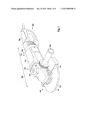
[0018] FIG. 2 shows, in a schematic representation, a detail view of a spindle of the hand power tool from FIG. 1, comprising the run-off securing device according to the invention disposed on the spindle,
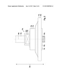
[0019] FIG. 3 shows, in a tool-side view, a detail view of the run-off securing device according to the invention,
[0020] FIG. 4 shows, in a machine-side view, a detail view of the run-off securing device according to the invention,
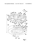
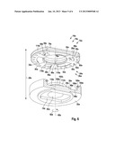
[0021] FIG. 5 shows a perspective detail view of the run-off securing device according to the invention in an opened state, with a section along the line V-V from FIG. 3,
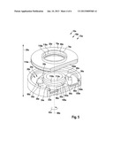
[0022] FIG. 6 shows a further perspective detail view of the run-off securing device according to the invention in an opened state, with a section along the line V-V from FIG. 3, and
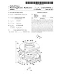
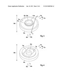
[0023] FIG. 7 shows a perspective detail view of an alternative run-off securing device according to the invention in an opened state, with an analogous section according to the line V-V from FIG. 3.
DESCRIPTION OF THE EXEMPLARY EMBODIMENTS
[0024] FIG. 1, in schematic representation, shows a hand power tool 42a realized as an angle grinder 44a, comprising a run-off securing device 10a according to the invention. The run-off securing device 10a in this case is realized as a run-off securing device of a hand power tool. The angle grinder 44a comprises a protective hood unit 46a, a hand power tool housing 48a, and a main handle 50a that extends, on a side 52a that faces away from a tool 14a, in the direction of a main extent direction 54a of the angle grinder 44a. The hand power tool housing 48a comprises a motor housing 56a for receiving an electric motor (not represented in greater detail here), and a gear unit housing 58a for mounting a gear unit (not represented in greater detail here). On the gear unit housing 58a there is an auxiliary handle 60a disposed on the angle grinder 44a. The auxiliary handle 60a extends transversely in relation to the main extent direction 54a of the angle grinder 44a.
[0025] FIG. 2, in a schematic representation, shows a detail view of a spindle 16a of the hand power tool 42a realized as an angle grinder 44a, comprising the run-off securing device 10a disposed on the spindle 16a. The spindle 16a extends perpendicularly in relation to the main extent direction 54a out of the gear unit housing 58a (not represented in greater detail here). Disposed on the spindle 16a is the run-off securing device 10a for preventing a clamping element 12a, realized as a clamping nut 62a, and/or the tool 14a, realized as a cutting disk 64a, from running off the spindle 16a. It is also conceivable, however, for the tool 14a to be realized as a grinding or polishing disk. For the purpose of receiving the run-off securing device 10a, the spindle 16a has, on an outer circumference, two flattened portions 66a that are disposed diametrically and thus form a double flat 70a. In this case, only one of the flattened portions 66a is represented in FIG. 2. The outer circumference of the spindle 16a is disposed in a plane running perpendicularly in relation to a rotation axis 68a of the spindle 16a. By means of the gear unit (not represented) and the electric motor (not represented) of the angle grinder 44a, the spindle 16a is driven so as to be rotatable about the rotation axis 68a. While the angle grinder 44a is in a working mode, the spindle 16a is driven in rotation counter-clockwise as viewed from the angle grinder 44a. In this case, the run-off securing device 10a, when in a mounted state, is likewise driven in rotation counter-clockwise.
[0026] The run-off securing device 10a comprises a transmission unit 18a, realized as a receiving flange 72a, which is provided to be coupled to the spindle 16a in a removable manner and which has at least one first transmission element 20a and at least one second transmission element 22a that is movable relative to the first transmission element 20a (FIGS. 3 and 4). When the run-off securing device 10a is in a mounted state, the second transmission element 22a is positively connected to the spindle 16a, for the purpose of transmitting torque. For this purpose, the second transmission element 22a has a driving contour 74a, which is realized so as to correspond to the double flat 70a of the spindle 16a (FIG. 4).
[0027] The first transmission element 20a is realized in the form of a disk, and has a bearing contact surface 76a for bearing contact of the tool 14a realized as a cutting disk 64a. Furthermore, the first transmission element 20a has an annular collar 78a, which is provided to receive the tool 14a (FIGS. 3 and 5). For this purpose, the tool 14a has a central opening, realized as a bore (not represented in greater detail here), which is pushed onto the collar 78a of the first transmission element 20a for the purpose of mounting the tool 14a, such that the tool 14a bears on the bearing contact surface 76a of the first transmission element 20a. The bearing contact surface 76a of the first transmission element 20a and a side of the tool 14a that bears on the bearing contact surface 76a have an adhesive coating (not represented in greater detail here), such that there is a large amount of friction between the bearing contact surface 76a of the first transmission element 20a and the side of the tool 14a that bears on the bearing contact surface 76a. It is also conceivable, however, for the bearing contact surface 76a and the side of the tool 14a that bears on the bearing contact surface 76a to have corresponding, ramp-type geometries that engage in each other. Likewise conceivable are other friction-increasing measures considered appropriate by persons skilled in the art, as well as other designs of the bearing contact surface 76a and of the side of the tool 14a that bears on the bearing contact surface 76a.
[0028] When the tool 14a is being mounted, the tool 14a, by means of the central opening, is pushed along an axial direction 28a onto the spindle 16a, until the tool 14a bears on the bearing contact surface 76a of the first transmission element 20a of the transmission unit 18a of the run-off securing device 10a that is already disposed on the spindle 16a. By means of an internal thread (not represented in greater detail here) of the clamping element 12a, the clamping element 12a, realized as a clamping nut 62a, is then screwed onto a thread 80a of the spindle 16a. The tool 14a is thereby clamped, together with the transmission element 18a, on the spindle 16a, the transmission element 18a being supported on the spindle 16a via the second transmission element 22a. By means of the clamping of the tool 14a between the clamping element 12a and the transmission unit 18a on the spindle 16a, a torque is transmitted from the spindle 16a onto the tool 14a. When the angle grinder 44a is in working mode, the tool 14a is driven in rotation counter-clockwise as viewed from the angle grinder 44a. When the angle grinder 44a is in working mode, the clamping element 12a is moved further along the spindle 16a in the direction of the angle grinder 44a by a rotation of the tool 14a and a friction between the clamping element 12a and a side of the tool 14a that bears on the clamping element 12a, by means of a pitch of the thread 80a of the spindle 16a and the internal thread of the clamping element 12a, such that a strong clamping force is produced to hold the tool 14a on the spindle 16a.
[0029] The angle grinder 44a comprises a braking device (not represented in greater detail here) for preventing the spindle 16a from coasting down in the case of an operation to switch off the angle grinder 44a by means of an interruption of an electric power supply through actuation of a switch (not represented in greater detail here). Upon the switching-off operation, the angle grinder 44a switches to a braking mode and brakes the spindle 16a by means of the braking device. In the braking mode, owing to the mass inertia the tool 14a continues to move counter-clockwise, or continues to move about the rotation axis 68a of the spindle 16a, such that a torque difference is produced between the tool 14a, the spindle 16a, the transmission unit 18a and the clamping element 12a. This torque difference results in a relative motion between the tool 14a, the transmission unit 18a and the clamping element 12a. Owing to a friction between the clamping element 12a and the inert tool 14a, the clamping element 12a is rotated concomitantly with the tool 14a, contrary to a direction of rotation generated when the angle grinder 44a is in working mode, such that a thread bias generated by the pitch of the internal thread of the clamping element 12a and of the thread 80a of the spindle 16a can be removed. As a result of this, the clamping element 12a can be released over an entire thread length of the thread 80a of the spindle 16a, and the clamping element 12a, together with the tool 14a, can run off the spindle 16a. For the purpose of preventing the clamping element 12a and/or the tool 14a from running off, the transmission unit 18a, realized as a receiving flange 72a, has a motion changing unit 24a, which is provided to transform a first relative motion between the first transmission element 20a and the second transmission element 22a into a second relative motion in a braking mode (FIG. 5). In this case, the first relative motion between the first transmission element 20a and the second transmission element 22a is a rotation about the rotation axis 68a. The second relative motion between the first transmission element 20a and the second transmission element 22a is a translation along the axial direction 28a. The rotation between the first transmission element 20a and the second transmission element 22a is produced, when in the braking mode, from the torque difference between the tool 14a and the transmission unit 18a. Owing to the resultant friction between the tool 14a and the bearing contact surface 76a of the first transmission element 20a, the tool 14a concomitantly rotates the first transmission element 20a, the second transmission element 22a being positively connected to the double flat 70a of the spindle 16a by means of the driving contour 74a. The first transmission element 20a in this case is movably mounted in the second transmission element 22a, which is realized in the form of a pot. The first transmission element 20a is mounted in the second transmission element 22a so as to be movable along a circumferential direction 82a and along the axial direction 28a.
[0030] The motion changing unit 24a is realized as a stroke unit 26a, which is provided to move the first transmission element 20a along the axial direction 28a as a result of the first relative motion, in particular the rotation, relative to the second transmission element 22a. The stroke unit 26a has a first stroke element 30a, which is realized so as to be integral with the second transmission element 22a. The first stroke element 30a is realized in the form of a ramp. Further, the stroke unit 26a has a second stroke element 32a, which generates the second relative motion, or the translation of the first transmission element 20a relative to the second transmission element 22a, as a result of the first relative motion, or the rotation of the first transmission element 20a relative to the second transmission element 22a, by means of an action in combination with the first stroke element 30a. The second stroke element 32a is likewise realized in the form of a ramp, and is realized so as to be integral with the first transmission element 20a (FIG. 6). In total, the first transmission element 20a has three second stroke elements 32a. The second transmission element 22a has three first stroke elements 30a, which correspond with the three second stroke elements 32a of the first transmission element 20a. It is also conceivable, however, for a number greater or less than three stroke elements 30a, 32a to be provided on the first transmission element 20a and on the second transmission element 22a. Depending on the requirement, persons skilled in the art will decide which number of stroke elements 30a, 32a is considered appropriate on the first transmission element 20a and on the second transmission element 22a.
[0031] The first stroke elements 30a extend in a uniformly distributed manner on a circular ring of 360° of the second transmission element 22a, along an angular range of between 30° and 60° in each case, around a central opening 84a of the second transmission element 22a, which opening is provided to receive the spindle 16a. The central opening 84a in this case is realized as a fit bore. The first stroke elements 30a have a pitch that, starting from a start point disposed on an inner surface 86a, extends in the direction of an end point disposed in a plane parallel to the inner surface 86a. When the second transmission element 22a is in the mounted state, the plane is disposed at a distance from the inner surface 86a, going from the spindle 16a in the direction of the mounted tool 14a.
[0032] The second stroke elements 32a extend in a uniformly distributed manner on a circular ring of 360° of the first transmission element 20a, along an angular range of between 30° and 60° in each case, around a central opening 88a of the first transmission element 20a, which opening is provided to receive the spindle 16a (FIG. 6). When the transmission unit 18a is in a mounted state, the second stroke elements 32a face in the direction of the inner surface 86a of the second transmission element 22a. The second stroke elements 32a have a pitch corresponding to the first stroke elements 30a. The pitch of the first stroke elements 30a and of the second stroke elements 32a in this case is as great as or greater than a pitch of the thread 80a of the spindle 16a, or of the internal thread of the clamping element 12a. When the tool 14a is in a clamped state, the second stroke elements 32a bear on the first stroke elements 30a. Upon the rotation of the first transmission element 20a relative to the second transmission element 22a, as a result of the braking mode, the second stroke elements 32a slide on the first stroke elements 30a. An axial stroke of the first transmission element 20a relative to the second transmission element 22a is thereby generated along the axial direction 28a. This axial stroke generates a clamping force in the direction of the tool 14a and of the clamping element 12a, such that the clamping element 12a and/or the tool 14a can be prevented from running off the spindle 16a.
[0033] The run-off securing device 10a comprises at least one limit stop element 34a, which is provided to limit the first relative motion between the first transmission element 20a and the second transmission element 22a, or the rotation of the first transmission element 20a relative to the second transmission element 22a (FIG. 5). The limit stop element 34a is disposed on the inner surface 86a of the second transmission element 22a that is constituted by a side 36a facing toward the first transmission element 20a. The first transmission element 20a in this case has at least one recess 38a (FIG. 6), which is provided to receive the limit stop element 34a when the transmission unit 18a is in a mounted state. In total, the run-off securing device 10a comprises three limit stop elements 34a on the second transmission element 22a, and three recesses 38a on the first transmission element 20a. It is conceivable, however, for a number greater or less than three limit stop elements 34a to be provided on the second transmission element 22a and for a number greater or less than three recesses 38a to be provided on the first transmission element 20a. Depending on the requirement, persons skilled in the art will decide which number of limit stop elements 34a is considered appropriate on the second transmission element 22a and which number of recesses 38a is considered appropriate on the first transmission element 20a.
[0034] The three limit stop elements 34a are disposed in a uniformly distributed manner along the circular ring of 360°, spaced apart from each other and spaced apart from the three first stroke elements 30a of the second transmission element 22a. Further, the three limit stop elements 34a have axial extents that run along the axial direction 28a. The axial extents in this case are selected in such a way that, when the transmission unit 18a is in a mounted state, the three limit stop elements 34a extend at least into the three recesses 38a of the first transmission element 20a. The three recesses 38a extend in a uniformly distributed manner on the circular ring of 360° of the first transmission element 20a, in each case along an angular range of between 15° and 30°, and, spaced apart in relation to each other and to the second stroke elements 32a, are disposed around the central opening 88a of the first transmission element 20a.
[0035] The limit stop elements 34a limit the rotation between the first transmission element 20a and the second transmission element 22a to an angular range defined by a dimension of the recesses 38a and by a dimension of the limit stop elements 34a. This allows deliberate release of the clamping element 12a, for example during a tool change. If the clamping element 12a is rotated clockwise, or contrary to the rotation direction, as viewed from the angle grinder 44a, in working mode, the first transmission element 20a is turned relative to the second transmission element 22a, until the limit stop elements 34a of the second transmission element 22a stop against peripheral regions 90a of the recesses 38a of the first transmission element 20a. By means of the stopping, or a bearing of the limit stop elements 34a against the peripheral regions 90a of the recesses 38a, the first transmission element 20a is fixedly coupled to the second transmission element 22a. A torque generated by unscrewing the clamping element 12a is supported, via the driving contour 74a, on the double flat 70a of the spindle 16a, and the clamping element 12a can be released and unscrewed from the spindle 16a.
[0036] Furthermore, the run-off securing device 10a has at least one lubricant receiver chamber 40a for receiving lubricant for the purpose of reducing a friction in the case of the first relative motion between the first transmission element 20a and the second transmission element 22a. The lubricant receiver chamber 40a is constituted by a lubricant pocket 92a. In total, a plurality of lubricant pockets 92a are disposed, uniformly spaced apart from each other, along a circular ring around the central opening 88a of the first transmission element 20a (FIG. 6). The lubricant pockets 92a are disposed in a side 94a of the first transmission element 20a that faces away from the bearing contact surface 76a. Further, lubricant pockets (not represented in greater detail here) are likewise disposed in the ramp-type first stroke elements 30a and in the ramp-type second stroke elements 32a, such that a lesser frictional resistance is produced as the ramp-shaped first stroke elements 30a slide on the ramp-shaped second stroke elements 32a during a rotation of the first transmission element 20a relative to the second transmission element 22a.
[0037] Furthermore, the second transmission element 22a has a bearing element 96a, which is disposed in a circular ring-shaped recess 98a in the inner surface 86a of the second transmission element 22a. The bearing element 96a is realized as a plain bearing in this case. In an alternative design, however, it is conceivable for the bearing element 96a to be realized as a rolling bearing. Also disposed in the circular ring-shaped recess 98a are a plurality of lubricant pockets (not represented in greater detail here), uniformly spaced apart from each other, for receiving lubricant.
[0038] The transmission unit 18a additionally has a first sealing element 100a and a second sealing element 102a, which are provided to protect the transmission unit 18a from the ingress of dust from an external environment and to prevent lubricant from emerging from the inside. The first sealing element 100a in this case is disposed in a first groove 104a of the second transmission element 22a, and the second sealing element 102a is disposed in a second groove 106a of the second transmission element 22a (FIG. 5). The first groove 104a is disposed in a side surface 108a of the second transmission element 22a. The side surface 108a extends perpendicularly in relation to the inner surface 86a of the second transmission element 22a and along an entire circumference of the second transmission element 22a, which circumference runs in a plane parallel to the inner surface 86a. The second groove 106a is disposed in a side 110a of a hollow cylinder 112a that surrounds the central opening 84a, which side faces toward the side surface 108a. The first sealing element 100a is pressed with an exact fit into the first groove 104a, and the second sealing element 102a is pressed with an exact fit into the second groove 106a.
[0039] The first transmission element 20a has a first sealing element receiver 114a that corresponds to the first groove 104a of the second transmission element 22a. The first sealing element receiver 114a is disposed along an outer circumference of the first transmission element 20a and extends along the entire outer circumference. The outer circumference of the first transmission element 20a runs in a plane that extends parallel to the bearing contact surface 76a. In this case, the first sealing element receiver 114a has an extent, along the axial direction 28a, that is greater than an extent of the first sealing element 100a along the axial direction 28a. A sealing function is thereby ensured in the case of an axial stroke of the first transmission element 20a relative to the second transmission element 22a.
[0040] Further, the first transmission element 20a has a second sealing element receiver 116a that corresponds to the second groove 106a of the second transmission element 22a. The second sealing element receiver 116a is disposed in an inside 118a of the central opening 88a of the first transmission element 20a and extends along an entire circumference of the central opening 88a. The circumference of the central opening 88a runs in a plane that extends parallel to the bearing contact surface 76a of the first transmission element 20a. The second sealing element receiver 116a has an extent along the axial direction 28a that is greater than an extent of the second sealing element 102a along the axial direction 28a. A sealing function is likewise thereby ensured in the case of an axial stroke of the first transmission element 20a relative to the second transmission element 22a. By means of the first sealing element 100a and the second sealing element 102a, the first transmission element 20a and the second transmission element 22a are connected to each other and fixed axially.
[0041] A second, alternative exemplary embodiment is represented in FIG. 7. Components, features and functions that remain substantially the same are denoted, basically, by the same references. To distinguish the exemplary embodiments, the letters a and b have been added to the references of the exemplary embodiments. The description that follows is limited substantially to the differences in relation to the first exemplary embodiment in FIGS. 1 to 6 and, in respect of components, features and functions that remain the same, reference may be made to the description of the first exemplary embodiment in FIGS. 1 to 6.
[0042] FIG. 7 shows a perspective detail view of an alternative run-off securing device 10b according to the invention in an opened state, with an analogous section according to the line V-V from FIG. 3. The run-off securing device 10b in this case can be disposed on a spindle of an angle grinder 44a, such as that shown in FIG. 1. The run-off securing device 10b comprises a transmission unit 18b, which is provided to be coupled to the spindle in a removable manner, and which has at least one first transmission element 20b and at least one second transmission element 22b that is movable relative to the first transmission element 20b. Furthermore, the transmission unit 18b comprises at least one motion changing unit 24b, realized as a stroke unit 26b, which is provided, in a braking mode, to at least partially transform a first relative motion between the first transmission element 20b and the second transmission element 22b into a second relative motion.
[0043] The stroke unit 26b has at least one first ramp-shaped stroke element 30b, which is realized so as to be integral with the second transmission element 22b. In total, the stroke unit 26b has three first stroke elements 30b, which are realized so as to be integral with the second transmission element 22b. Further, the stroke unit 26b has at least one second stroke element 32b, which is disposed on a side 94b of the first transmission element 20b that faces away from a bearing contact surface 76b. In total, the stroke unit 26b has three second stroke elements 32b. The second stroke elements 32b are realized as roll bodies 120b. The roll bodies 120b are disposed in recesses 122b in the side 94b of the first transmission element 20b that faces away from the bearing contact surface 76b. The recesses 122b are disposed along a circular ring, in a uniformly distributed manner and spaced apart from each other, in the first transmission element 20b. The roll bodies 120b of the first transmission element 20b correspond with the ramp-shaped first stroke elements 30b of the second transmission element 22b. In an alternative design, however, it is conceivable for the first stroke elements 30b to be realized so as to be integral with the first transmission element 20b, and for the roll bodies 120b to be disposed on the second transmission element 22b.
[0044] Upon a rotation of the first transmission element 20b relative to the second transmission element 22b, as a result of a braking mode, the roll bodies 120b roll along the ramp-shaped first stroke elements 30b and thus generate an axial stroke along an axial direction 28b of the first transmission element 20b relative to the second transmission element 22b.
User Contributions:
Comment about this patent or add new information about this topic:
Images included with this patent application:
 |  |
 |  |
 |  |
 |
| Similar patent applications: | |
| Date | Title |
|---|---|
| 2012-11-22 | Quick change clamping device |
| 2009-07-09 | Tool connecting device |
| 2010-07-15 | Mechanical coupling devices |
| 2013-03-14 | Apparatus for treating surfaces of wafer-shaped articles |
| 2013-05-23 | Rotation tool installation and removal device and said rotation tool |
| New patent applications in this class: | |
| Date | Title |
|---|---|
| 2016-01-14 | Chuck and clamp with quick change function |
| 2015-03-05 | Positioning board of chuck |
| 2014-12-04 | Floating chuck assembly for a rotary cutting machine |
| 2014-10-09 | Device for employment in a machine tool as well as machine tool |
| 2014-10-02 | Chuck structure for substrate cleansing equipment |
| New patent applications from these inventors: | |
| Date | Title |
|---|---|
| 2021-07-01 | Sealing device for sealing at least one storage and/or packaging device for durable goods, particularly machine tools, and/or for sealing at least one piece of information |
| 2021-07-01 | Electronic module, in particular for a hand-held power tool |
| 2017-06-22 | Mobile function device |
| 2017-06-22 | Hand-held tool system |
| 2017-06-22 | Mobile functional apparatus |
| Top Inventors for class "Chucks or sockets" | |
| Rank | Inventor's name |
|---|---|
| 1 | Franz Haimer |
| 2 | Peter Schenk |
| 3 | Hans-Dieter Mack |
| 4 | Eugen Hangleiter |
| 5 | Eugen A. Bordeianu |