Patent application title: HEAT SINK HAVING JUXTAPOSED HEAT PIPES AND METHOD FOR MANUFACTURING THE SAME
Inventors:
Chun-Hung Lin (New Taipei City, TW)
Chun-Hung Lin (New Taipei City, TW)
Tung-Yang Shieh (New Taipei City, TW)
Yen-Hsiang Chiu (Newtaipei City, TW)
Chun-Yi Lee (New Taipei City, TW)
Assignees:
COOLER MASTER CO., LTD.
IPC8 Class: AF28D1504FI
USPC Class:
16510426
Class name: Liquid fluent heat exchange material utilizing change of state utilizing capillary attraction
Publication date: 2012-12-20
Patent application number: 20120318480
Abstract:
The present invention relates to a heat sink having juxtaposed heat pipes
and a method for manufacturing the same. The heat sink includes a base, a
plurality of heat pipes and a pair of side strips. The base has a surface
on which an open trough and an insertion trough on both sides of the open
trough are provided. Each heat pipe has an evaporating section. The
evaporating sections are juxtaposed in the open trough and adhered to
each other. Each evaporating section has a planar surface. The side
strips are fixed into the insertion troughs and protrude from the surface
of the base. The planar surface of each evaporating section and the outer
surface of each side strip are coplanar. By this structure, the thermal
contact surface between the heat pipes and electronic heat-generating
sources is increased, so that the heat-dissipating efficiency of the heat
sink is improved.Claims:
1. A heat sink having juxtaposed heat pipes, including: a base having a
surface, the surface being provided with an open trough and insertion
troughs on both sides of the open trough; a plurality of heat pipes each
having an evaporating section, the evaporating sections being juxtaposed
into the open trough and adhered to each other, each of the evaporating
sections having a planar surface; and a pair of side strips fixed into
the insertion troughs and protruding from the surface of the base, the
planar surfaces of the evaporating sections and outer surfaces of the
side strips being coplanar.
2. The heat sink having juxtaposed heat pipes according to claim 1, wherein the base is an aluminum-made element.
3. The heat sink having juxtaposed heat pipes according to claim 2, wherein a middle portion of the base is formed with a protruding stage, the surface is formed on the protruding stage.
4. The heat sink having juxtaposed heat pipes according to claim 3, wherein the open trough comprises at least two grooves, at least one dividing strip is formed between any adjacent two of the grooves, a top surface of a free end of the dividing strip is located in a level lower than that of the surface, so that a height difference is formed between the dividing strip and the surface.
5. The heat sink having juxtaposed heat pipes according to claim 1, wherein the heat-conducting coefficient of the side strip is larger than that of the base.
6. The heat sink having juxtaposed heat pipes according to claim 1, wherein the side strip is a copper-made element.
7. The heat sink having juxtaposed heat pipes according to claim 1, further including a heat-dissipating fin set connected above the base.
8. The heat sink having juxtaposed heat pipes according to claim 7, wherein the heat-dissipating fin set is provided with a plurality of communicating holes, each of the heat pips has a condensing section extending from the evaporating section, the condensing sections are disposed into the communicating holes.
9. A heat sink having juxtaposed heat pipes, including: a base having a surface, the surface being provided with an open trough; a plurality of heat pipes each having an evaporating section, the evaporating sections being juxtaposed into the open trough and adhered to each other, each of the evaporating sections having a planar surface; and a pair of side strips fixed into base and protruding from the surface of the base, the planar surfaces of the evaporating sections and outer surfaces of the side strips being coplanar.
10. The heat sink having juxtaposed heat pipes according to claim 9, wherein the base is an aluminum-made element.
11. The heat sink having juxtaposed heat pipes according to claim 10, wherein a middle portion of the base is formed with a protruding stage, the surface is formed on the protruding stage.
12. The heat sink having juxtaposed heat pipes according to claim 11, wherein the open trough comprises at least two grooves, at least one dividing strip is formed between any adjacent two of the grooves, a top surface of a free end of the dividing strip is located in a level lower than that of the surface, so that a height difference is formed between the dividing strip and the surface.
13. The heat sink having juxtaposed heat pipes according to claim 9, wherein the heat-conducting coefficient of the side strip is larger than that of the base.
14. The heat sink having juxtaposed heat pipes according to claim 9, wherein the side strip is a copper-made element.
15. The heat sink having juxtaposed heat pipes according to claim 9, further including a heat-dissipating fin set connected above the base.
16. The heat sink having juxtaposed heat pipes according to claim 15, wherein the heat-dissipating fin set is provided with a plurality of communicating holes, each of the heat pips has a condensing section extending from the evaporating section, the condensing sections are disposed into the communicating holes.
17. A method for manufacturing a heat sink having juxtaposed heat pipes, the method including steps of: a) providing a base having an open trough; b) applying solder on inner walls and both sides of the open trough; c) providing a plurality of heat pipes and a pair of side strips, one end of each heat pipe being juxtaposed in the open trough, the pair of side strips being adhered to the base and located on both sides of each heat pipe; d) providing a heating apparatus, disposing a semi-finished product after the step c) into the heating apparatus, thereby soldering the heat pipes and the side strips on the base; and e) providing a pressing die for pressing the heat pipes and the side strips, whereby the heat pipes are adhered to each other and formed with a planar surface coplanar with the side strips.
18. The method according to claim 17, wherein the base is provided with an insertion trough on both sides of the open trough respectively, the solder is applied on inner walls of the insertion troughs, the side strips are inserted into the insertion troughs.
19. The method according to claim 17, wherein the planar surface of each heat pipe and the side strips protrude from the surface of the base.
20. The method according to claim 17, further including a step f) of providing a grinding tool for grinding the planar surfaces of the heat pipes and the side strips.
Description:
BACKGROUND OF THE INVENTION
[0001] 1. Field of the Invention
[0002] The present invention relates to a heat sink, and in particular to a heat sink having juxtaposed heat pipes and a method for manufacturing the same.
[0003] 2. Description of Prior Art
[0004] A heat-conducting module constituted by combining heat pipes with a heat-conducting base, or a heat sink constituted by combining heat-dissipating fins and heat pipes can conduct or dissipate the increasing heat generated by current processors. Thus, such a heat-conducting module or heat sink has replaced the conventional heat-dissipating structure constituted by merely heat-dissipating pieces. However, it is an important issue to combine heat pipes with a heat-conducting base to generate a better heat-conducting or heat-dissipating effect.
[0005] The conventional heat-dissipating module includes a heat-conducting block and a plurality of heat pipes. The heat-conducting block is provided with a plurality of grooves parallel to one another. A dividing strip is formed between two adjacent grooves. The heat pipes are disposed into the grooves respectively. A pressing die is used to press the respective heat pipes, whereby each heat pipe is formed with a planar surface in flush with the end surface of the dividing strip.
[0006] When the above-mentioned structure is used to dissipate the heat of an electronic heat-generating source, the planar surfaces of the heat pipes and the dividing strips are brought into thermal contact with the electronic heat-generating source. However, since the heat-conducting coefficient of the dividing strip is much smaller that that of the heat pipe, the resultant heat-conducting efficiency of the whole structure is limited. On the other hand, since the heat pipes are separated from each other by the dividing strips, if one heat pipe is inactive, the other heat pipes cannot help the inactive heat pipe to conduct the heat. As a result, the electronic heat-generating source may suffer damage or burn down. Thus, the above-mentioned structure still has room for improvement.
SUMMARY OF THE INVENTION
[0007] The present invention is to provide a heat sink having juxtaposed heat pipes and a method for manufacturing the same. The respective heat pipes are juxtaposed and adhered to each other, thereby increasing the thermal contact area between the respective heat pipes and an electronic heat-generating source. By this arrangement, the heat-dissipating efficiency of the heat sink is increased greatly.
[0008] The present invention is to provide a heat sink having juxtaposed heat pipes, including a base, a plurality of heat pipes and a pair of side strips. The base has a surface. The surface is provided with an open trough and insertion troughs on both sides of the open trough respectively. Each of the heat pipes has an evaporating section. The evaporating sections are juxtaposed into the open trough and adhered to each other. Each of the evaporating section has a planar surface. The pair of side strips is fixed into the insertion troughs and protrudes from the surface of the base. The planar surfaces of the evaporating sections and outer surfaces of the side strips are coplanar.
[0009] The present invention is to provide a heat sink having juxtaposed heat pipes, including a base, a plurality of heat pipes and a pair of side strips. The base has a surface on which an open trough is provided. Each of the heat pipes has an evaporating section. The evaporating sections are juxtaposed into the open trough and adhered to each other. Each of the evaporating sections has a planar surface. The pair of side strips is fixed to the base and protrudes from the surface of the base. The planar surfaces of the evaporating sections and outer surfaces of the side strips are coplanar.
[0010] The present invention provides a method for manufacturing a heat sink having juxtaposed heat pipes, the method including steps of:
[0011] a) providing a base having an open trough;
[0012] b) applying solder on inner walls and both sides of the open trough;
[0013] c) providing a plurality of heat pipes and a pair of side strips, one end of each heat pipe being juxtaposed in the open trough, the pair of side strips being adhered to the base and located on both sides of each heat pipe;
[0014] d) providing a heating apparatus, disposing a semi-finished product after the step c) into the heating apparatus, thereby soldering the heat pipes and the side strips on the base; and
[0015] e) providing a pressing die for pressing the heat pipes and the side strips, whereby the heat pipes are adhered to each other and formed with a planar surface coplanar with the side strips.
[0016] The present invention has advantageous features as follows. The side surfaces of the respective heat pipes are adhered to each other. If one heat pipe is inactive, the other adjacent heat pipes can still conduct the heat of an electronic heat-generating source, so that the electronic heat-generating source can be kept in a lower working temperature. The base is provided with troughs, so that the side strips and the heat pipes can be leveled and ground.
BRIEF DESCRIPTION OF DRAWING
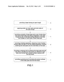
[0017] FIG. 1 is a flow chart showing the method for manufacturing the heat sink of the present invention;
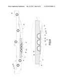
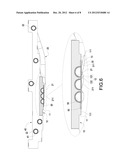
[0018] FIG. 2 is an exploded perspective view showing the heat sink of the present invention;
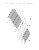
[0019] FIG. 3 is an assembled view showing the respective heat pipes of the present invention before the heat pipes being leveled;
[0020] FIG. 4 is a cross-sectional view of FIG. 3;
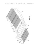
[0021] FIG. 5 is an assembled view showing the respective heat pipes of the present invention after the heat pipes being leveled;
[0022] FIG. 6 is a cross-sectional view of FIG. 5;
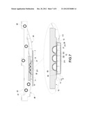
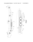
[0023] FIG. 7 is a schematic view showing an operating state of the heat sink of the present invention is applied to an electronic heat-generating source; and
[0024] FIG. 8 is an assembled cross-sectional view showing another embodiment of the present invention.
DETAILED DESCRIPTION OF THE INVENTION
[0025] The detailed description and technical contents of the present invention will become apparent with the following detailed description accompanied with related drawings. It is noteworthy to point out that the drawings is provided for the illustration purpose only, but not intended for limiting the scope of the present invention.
[0026] Please refer to FIGS. 2 and 4. The present invention provides a heat sink having juxtaposed heat pipes, which includes a base 10, a plurality of heat pipes 20, and a pair of side strips 30.
[0027] The base 10 is made of metallic materials such as aluminum or alloys thereof. In the present embodiment, the base 10 is formed into an H-shaped plate. The shape of the base 10 is not limited thereto, and may be formed into other shapes. The middle portion of the base 10 is provided with a protruding stage 11. The protruding stage 11 has a surface 111. The surface 111 is provided with an open trough 12. The interior of the open trough 12 is formed with three grooves 121. The number of the grooves 121 is not be limited thereto, and may be two grooves 121. At least one dividing strip 122 is formed between any adjacent two of the grooves 121. The top surface of the free end of the dividing strip 122 is located in a level lower that that of the surface 111, so that a height difference is formed between the dividing strip 122 and the surface 111. On the surface 111 of the base 10, an insertion trough 13 is formed on each side of the open trough 12. The insertion trough 13 is formed into a T shape. However, the shape of the insertion trough 13 is not limited thereto, and may be other suitable shapes.
[0028] The interior of the heat pipe 20 has a wick structure and working fluid. The liquid/vapor phase change of the working fluid and a liquid-reflowing mechanism caused by the wick structure are used for conducting the heat continuously. In the present embodiment, there are three heat pipes 20. Each of the heat pipes 20 has an evaporating section 21 and one or two condensing sections 22 extending from the evaporating section 21. As shown in FIG. 3, each of the evaporating sections 21 are disposed in the open trough 12 of the protruding stage 11 in parallel to each other.
[0029] The side strips 30 are made of metallic materials such as copper and alloys thereof. The heat-conducting coefficient of the side strip 30 is larger than that of the base 10. The side strip 30 in the present embodiment is substantially formed into a T shape. The two side strips 30 are inserted into the insertion troughs 13 respectively. A portion of the side strip 30 protrudes from the surface 111 of the base 10. One end of the side strip 30 away from the insertion trough 13 has an outer surface 311.
[0030] The heat sink of the present invention further includes a heat-dissipating fin set 40 which is constituted by overlapping a plurality of heat-dissipating fins. Each of the heat-dissipating fins is provided with a plurality of communicating holes 41. The middle area of the heat-dissipating fin set 40 is connected above the base 10. The condensing section 22 of each heat pipe 20 is disposed into the communicating hole 41.
[0031] Please refer to FIGS. 1 to 6. The present invention further provides a method for manufacturing a heat sink having juxtaposed heat pipes. Please refer to FIGS. 1 and 2. In a step a), a base 10 is provided, on which an open trough 12 and insertion troughs 13 are provided. Please refer to FIGS. 1 and 4. In a step b), solder is applied into the inner walls of the open trough 12 and the insertion troughs 13 on both sides of the open trough 12. In a step c), one end of each heat pipe 20 is disposed in the open trough 12. Each of the side strips 30 is adhered to the insertion trough 13 of the base 10 and located on both sides of each heat pipe 20. In a step d), the semi-finished product after the above steps is disposed into a heating apparatus (not shown), so that the heat pipes 20 and the side strips 30 are soldered in the open trough 12 and the insertion troughs 13 of the base 10. Please refer to FIGS. 1 and 6. In a step e), a plate-like pressing die (not shown) is used to press the heat pipes 20 and the side strips 30, so that the side surfaces of each heat pipe 20 are adhered to each other and are formed with a planar surface 211 coplanar with each side strip 30.
[0032] The method of the present invention further includes a step f) of providing a grinding tool (not shown) for grinding the planar surface 211 of each heat pipe 20 and each side strip 30. After finishing the above steps, the evaporating sections 21 of the heat pipes 20 are adhered to each other without any gap. The planar surface 211 of the evaporating section 21 and the outer surface 31 of each side strip 30 protrude from the surface 111 of the base 10.
[0033] Please refer to FIG. 7. The heat sink of the present invention can be applied to an electronic heat-generating source 8 of a printed circuit board 7. In assembly, the planar surface 211 of each evaporating section 21 and the outer surface 31 of each side strip 30 are adhered to the surface of the electronic heat-generating source 8. At this time, the heat generated by the electronic heat-generating source 8 is directly conducted to the side strips 30 and the evaporating sections 21. After the side strips 30 and the evaporating sections 21 receive the heat, the working fluid in the heat pipes 20 evaporates to become vapor. The vapor caries away the heat and flows toward a low-temperature region of the heat pipe 20. When the vapor reaches the condensing section 22, the vapor condenses in the condensing section 22 by means of the heat exchange of the heat-dissipating fins of the heat-dissipating fin set 40 with external air. The condensed working liquid reflows to the evaporating section 21 by means of the capillary force in the wick structure.
[0034] Please refer to FIG. 8. In addition to the above embodiment, each side strip 30 can be fixed onto the surface 111 of the base 10 by soldering. Each side strip 30 protrudes from the surface 111 of the base 10. The evaporating section 21 of each heat pipe 20 is disposed in the open trough 12 of the base 10. The pressing tool is used to press and level the evaporating section 21 of each heat pipe 20, so that the planar surface 211 of each evaporating section 21 and the outer surface 31 of each side strip 30 can form a coplanar structure.
[0035] Although the present invention has been described with reference to the foregoing preferred embodiments, it will be understood that the invention is not limited to the details thereof. Various equivalent variations and modifications can still occur to those skilled in this art in view of the teachings of the present invention. Thus, all such variations and equivalent modifications are also embraced within the scope of the invention as defined in the appended claims.
User Contributions:
Comment about this patent or add new information about this topic:
| People who visited this patent also read: | |
| Patent application number | Title |
|---|---|
| 20160067586 | FACE MASK WITH IMPACT DAMPENING |
| 20160067585 | Sports Training Apparatus |
| 20160067584 | SYSTEM AND METHOD FOR ANALYZING ATHLETIC ACTIVITY |
| 20160067583 | PUTTING TRAINER DEVICE |
| 20160067582 | ENHANCED GOLF SIMULATION SYSTEM |
Images included with this patent application:
 |  |
 |  |
 |  |
 |
| Similar patent applications: | |
| Date | Title |
|---|---|
| 2013-05-30 | Heat sink with heat bus and fin structure |
| 2013-05-30 | Heat dissipation device with fixing member for heat pipe thereof |
| 2013-05-23 | Vapor chamber with integrally formed wick structure and method of manufacturing same |
| 2009-02-12 | Heat sink and manufacturing method thereof |
| 2011-09-22 | Modular heat sink and method for fabricating same |
| New patent applications in this class: | |
| Date | Title |
|---|---|
| 2019-05-16 | Method for preparing porous wick and product prepared by the same |
| 2019-05-16 | Semiconductor device assembly with vapor chamber |
| 2019-05-16 | Straight-through structure of heat dissipation unit |
| 2018-01-25 | Diphasic cooling loop with satellite evaporators |
| 2017-08-17 | Heat pipe |
| New patent applications from these inventors: | |
| Date | Title |
|---|---|
| 2022-08-25 | Water-cooled and flow-controlled heat dissipation system used in cabinet and control method thereof |
| 2022-08-04 | Wind-guiding type heat dissipation module |
| 2022-07-28 | Water-repellent resin, water-repellent fabric, and fabricating method thereof |
| 2022-03-31 | Heat dissipating module having auxiliary fan |
| 2022-01-13 | Anti-staining resin, anti-staining fabric and fabricating method thereof |
| Top Inventors for class "Heat exchange" | |
| Rank | Inventor's name |
|---|---|
| 1 | Levi A. Campbell |
| 2 | Chun-Chi Chen |
| 3 | Tai-Her Yang |
| 4 | Robert E. Simons |
| 5 | Richard C. Chu |