Patent application title: SELF-MOUNTING MODULAR STRUCTURE, FOR CONSTITUTING PROTECTED ENVIRONMENTS
Inventors:
Tiziano Pili (Albate, IT)
IPC8 Class: AE04B1344FI
USPC Class:
52646
Class name: Openwork; e.g., truss, trellis, grille, screen, frame, or rebar chair components adjustably or collapsibly connected three-dimensional space-defining
Publication date: 2012-12-13
Patent application number: 20120311954
Abstract:
A self-mounting modular structure comprises profiled peripheral columns
(1, T) which exhibit upper overlapped and spaced fulcrums (2, 2'),
wherein the rear portions of two series of crosspieces (3, 3') engage,
the front ends whereof connect to upper (4) and lower (41) fulcrums of
the central support rack (5) of a control unit (6) the stem whereof (7)
connects, through a coaxial joint (8) and movable radial levers (9), to
the front extensions (3'') of the lower crosspieces (31). In feedback,
the stem (7) rises and pushes the columns (1, T) outwards, which move on
standard or roller tracked wheels (11), causing the lifting in the middle
and "at the ceiling" of the crosspieces (3, 3'), located within the same
columns. Peripheral section bars (19), also comprised in closure in the
peripheral columns (1, T), delimit the structure with roll-up sheets
(21), along with an upper cover (22) engaged, in the middle, with said
rack (5).Claims:
1. Self-mounting structure for constituting protected environments,
characterized in that it comprises profiled peripheral bearing columns
(1, 1') whereon overlapped spaced fulcrums (2, 2') are provided, wherein
the rear portions of crosspieces (3, 3') engage, the front ends whereof
engage in upper (4) and lower (4') fulcrums of the central support rack
(5) of an opening and closing control unit (6); said unit (6) comprising
a stem (7, 7') with coaxial joint (8) on the periphery whereof the front
ends of levers (9) are radially pivoted which, on the opposite side,
engage in fulcrums (4'') provided on the front extensions (3'') of said
lower crosspieces (3'); said columns (1, 1') further comprising the upper
fulcrums (19') of peripheral section bars (19) the lower ends whereof
slidingly engage, through wheels (20), in the vertical guides (21)
arranged along the adjacent columns (1, 1') being provided with standard
wheels or adjustable lower tracked wheels (11) and said peripheral
section bars (19) comprising roller mechanisms for environment delimiting
peripheral sheets.
2. Self-mounting modular structure according to claim 1, characterized in that said stem (7) of said control unit (6), in feedback motion, carries out an outward radial thrust (R) on said columns (1, 1') which move on standard or tracked wheels with multiple rollers (11), causing the lifting of said crosspieces (3, 3') and of said peripheral section bars (19), along with the control unit itself (6), in the middle and at the "ceiling", all comprised within the inside environments (10) of said peripheral columns (1, 1').
3. Self-mounting modular structure according to claim 1, characterized in that it is delimited by roll-up sheets (24) comprised in said section bars (19) and by a top covering (25) which peripherally engages with the section bars themselves (19) and centrally with the support rack (5) of said control unit (6).
4. Self-mounting modular structure according to claim 1, characterized in that peripheral columns (1, 1'), in their closed condition before set up, at the center are side by side, shaped as a "parallelepiped container" wherein the following items are composed, arranged and preassembled: said crosspieces (3, 3') and said structural stabilizing section bars (19), the relative coupling and positioning means, the positioning and standing members (11), said opening and closing control unit (6), and said peripheral roll-up (24) and top covering (25) sheets for delimiting the environment to be constituted.
5. Self-mounting modular structure according to claim 1, characterized in that peripheral columns (1) have a generic L shaped angular section with equal wings.
6. Self-mounting modular structure according to claim 1, characterized in that peripheral columns (1') have a generic T or cross shaped angular section with equal wings.
7. Self-mounting modular structure according to claim 1, characterized in that said tracked wheels (11) consist of a plurality of wheels (12) associated to each other by continuous chain tracks (13) and pivoting on pins (14) of a flange (15) that in turn rotates about a central horizontal axis (16) comprised on a self-aligning bracket (17); each of said brackets (17) being provided with adjustment, vertical fixing and position constraining means consisting of a motor reduction unit (18) and a cam (18') whereon a pawl (18'') positions; the configuration of said tracked wheels (11) being with three, four or more wheels (12).
8. Self-mounting modular structure according to claim 1, characterized in that said opening/closing control unit (6) consists of mechanical means such as: scroll/worm screw or gear/rack, with manual control through crank lever and coupler (7') of said stem (7), or with electromechanical control with motor reduction unit or remote control.
9. Self-mounting modular structure according to claim 1, characterized in that said opening/closing control unit (6) consists of a hydraulic piston with button- or remote control-actuated control unit.
10. Self-mounting modular structure for constituting protected environments according to claim 1, characterized in that it is modular with other equal self-mounting structures by means of columns (1') provided with longitudinal profiled extensions (1') with T or cross shaped sections.
Description:
[0001] The invention relates to a self-mounting modular structure for
constituting protected environments, especially suitable for making
delimited areas such as boxes, exhibition stands, curtains, gazebos or
for making environments and/or living spaces for temporary use in
building yards and/or in areas affected by natural calamities, due to
which the populations affected must be aided, evacuated and gathered in
relief centres to be set up and organised in short times.
[0002] It is known that the current quick intervention techniques, especially for those related to natural calamities are based on the setup of tent camps and/or emergency shelters to be set up in protected areas as far as possible from the affected territories.
[0003] It is also known that even in non hazardous conditions, such as for example markets, fairs, and exhibitions in general, the spaces authorised for the exhibition and/or the sale of products are always delimited and are used for the setup of awnings, the positioning of motor vehicles with side curtains supported by bars and pickets, the assembly of prefabricated huts, the arrangement of stalls with sunshades and other corresponding or similar means, to be transported, assembled and disassembled in predetermined places.
[0004] In any case, although useful for the commercial purposes of daily use and/or for the emergency safety purposes for hazardous events in general, the means currently available are not functional and rationale, are not comfortable to use, require much time for the setup, for preparing the sites to use, for the subsequent dismantling, for storing the materials to use and store, and last but not least, for the need of a large physical presence of skilled personnel available to work manually, hardly and quickly, even in critical conditions.
[0005] The object of this invention is to eliminate the above drawbacks by a self-mounting modular structure for constituting delimited and protected environments characterised according to what claimed in the first claim. Further features are defined in the dependent claims.
[0006] The advantages achieved by the present invention essentially consist in that said modular structure consists of a series of devices, preassembled and already steadily combined with one another, arranged for allowing without difficulties, the quick and automatic assembly or dismantling thereof, through the action of a single operator working with manual, semiautomatic or automatic means.
[0007] The self-mounting modular structure for constituting protected environments, according to the invention, consists of profiled peripheral bearing columns, wherein between the following are arranged: [0008] extractable upper crosspieces, centrally and peripherally supported, for constituting and stabilising the bearing structure and supporting a cover sheet, [0009] upper peripheral section bars for completing the structural stability and containing peripheral roll-up sheets constituting the walls, [0010] standard or adjustable lower tracked wheels for in line setup, with adjustment means according to the planar irregularities of the supporting grounds, [0011] a mechanical, electro-mechanical or oil-pressure control unit, with manual, electrical or remotely controlled drive, for opening and closing the structure as a whole, according to the arrangement of the crosspieces and of the upper peripheral section bars.
[0012] The invention is described in detail hereinafter, according to an embodiment with single module, given only by way of a non-limiting example, with reference to the attached drawings, wherein:
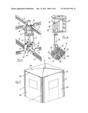
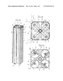
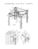
[0013] FIGS. 1a, 1b, 1c show a self-mounting modular structure according to the invention, in the totally closed condition for transporting and/or laying and/or prior to assembly, in perspective view and enlarged, the same structure in a top and below plan view,
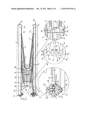
[0014] FIG. 2 shows an example of a single self-mounting modular structure, seen from the side and in opening or closing step, with enlargements of the details: upper (A) and lower (B) of connection between the upper crosspieces and the central support rack for an opening/closing control unit, and (C) special tracked wheels with adjustable setup,
[0015] FIG. 3 shows a perspective view of the same single self-mounting modular structure with the crosspieces in open position and the peripheral section bars in opening step (dotted) and in totally open position (uninterrupted line),
[0016] FIG. 4 shows an example of top hooking of the peripheral section bars,
[0017] FIG. 5 shows the perspective view of the central opening/closing control unit and of the support rack thereof, with the connecting points of the front ends of the upper crosspieces,
[0018] FIG. 6 shows the perspective view of one of the wheels of the "tracked" type with the position adjustment means according to the irregularities of the support grounds of the uprights, and
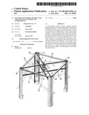
[0019] FIG. 7 shows the perspective view of a single self-mounting modular structure totally set up.
[0020] With reference to the above figures, a single self-mounting modular structure substantially consists of peripheral columns (1), generally with angular L section with same wings, which in closed condition prior to the setup at the centre are side by side, forming a "parallelepiped container" wherein the following items are composed, arranged and preassembled: the crosspieces and the section bars stabilising and delimiting the structural assembly, the relative coupling and positioning means, the standing members, the opening and closing control unit, the peripheral and top sheets delimiting the environment to be constituted.
[0021] In the top side, the columns (1) exhibit overlapped spaced fulcrums (2, 2') wherein the rear ends of two series of crosspieces (3, 3') engage, the front ends whereof connect to upper (4) and lower (4') fulcrums of the central support rack (5) of a control unit (6) comprising a movable extensible stem (7).
[0022] In turn, the stem (7) comprises a coaxial joint (8) on the periphery whereof there are radially pivoted the front ends of movable levers (9) which on the opposite side engage in fulcrums (4'') provided on the front extensions (3'') of said lower crosspieces (3').
[0023] In the closed condition of the modular structure, the stem (7) is totally extended downwards and the crosspieces (3, 3') are arranged vertically within the space (10) formed by the columns (1) side by side at the centre.
[0024] Upon the setup of the modular structure, for forming a protected environment, the stem (7) is returned upwards either by a control unit (6) (as shown), or by a crank lever that may be hooked to a lower eyebolt (7') of the same stem, pulling the radial levers (9) in the movement by means of the coaxial joint (8). In turn, the levers (9) return both the crosspieces (3'), engaged at the ends (3''), and the central rack (5) connected to the crosspieces (3') through the fulcrums (4'), upwards. The same rack (5), moved upwards, returns the upper crosspieces (3) too, which rotate around the fulcrums (4), to the same position. Such coordinated actions, besides causing the lifting in the middle and "at the ceiling" of the crosspieces (3, 3'), which project from the space (10), push the columns (1) outwards, in radial direction (R) relative to the rack (5), making it slide either directly on traditional wheels, for less expensive configurations or for applications on levelled and regular grounds, or on tracked wheels as illustrated (11); each of said tracked wheels consisting of a plurality of rollers (12) associated to one another through continuous chain tracks (13) and pivoting on pins (14) of a flange (15) which in turn can rotate about a central horizontal axis (16) comprised on a self-aligning bracket (17). Each bracket (17) is provided with means for the adjustment, vertical fixing and constraining into position, for example consisting of a motor reduction unit (18) and a cam (18') whereon a pawl (18'') slides and positions. The configuration of said tracked wheels (11), with three, four or more rollers (12) allows a proper horizontal setup of the structure, irrespective of any changes in the level of the grounds whereon the positioning thereof is required.
[0025] Within the upper portion of the columns (1) there are also arranged the fulcrums (19') of the upper ends of section bars (19) the lower ends whereof engage sliding-wise, through rollers (20), into the vertical guides (21) provided along the adjacent columns (1). During the outwards spreading and the lifting at the middle and up to the "ceiling" of the crosspieces (3, 3'), the lower ends of the section bars (19) are also returned upwards, up to arranging and fixing horizontally between the upper ends (22) of said adjacent columns, and automatically constraining in place the sliding ends thereof (lower 19'') by stops (23) which, at the end of the extension and upon the steady positioning of the columns (1) on the ground, with retraction of the wheels (11), are pushed upwards by sliding travel end pushers (23') connected to plates (23'') associated to said brackets (17). In such open position, the section bars (19) are also arranged and engaged horizontally, between the upper ends (22) of the same columns (1) and at the same level as said upper crosspieces (3), contributing to both the general stability of the structure and to the final delimitation thereof, generated by sheets (24) that may be unwound, downwards and up to the ground, by the roll-ups comprised in the same section bars (19), sliding in special vertical guides, provided along the same columns.
[0026] A cover (25), peripherally constrained to said section bars (19), and in the middle of said rack (5), totally covers the environment during the opening action.
[0027] The opening/closing control unit (6) of the structure may be made by mechanical means, such as: scroll/worm screw or gear/rack, with manual control with crank lever or with electromechanical control with motor reduction unit, or even with hydraulic piston with combined control unit (as indicated in the drawings by way of an example), also actuable by remote control.
[0028] Electrical sockets for lighting and auxiliary sockets for other useful utilities are provided on the columns (1), with power supply obtainable from the mains or batteries, with panel or remote control.
[0029] Two or more modular structures as described may be composed, placing them side by side to one another, for constituting larger environments; other possible solutions may be realised by the use of columns (1) set up with longitudinal profiled extensions (1') forming sections shaped as T or cross, as indicated by a dashed line in FIG. 1b.
User Contributions:
Comment about this patent or add new information about this topic:
| People who visited this patent also read: | |
| Patent application number | Title |
|---|---|
| 20130290287 | EXECUTING USER-DEFINED FUNCTION ON A PLURALITY OF DATABASE TUPLES |
| 20130290286 | METHOD, APPARATUS, AND SYSTEM FOR OPERATING SHARED RESOURCE IN ASYNCHRONOUS MULTIPROCESSING SYSTEM |
| 20130290285 | DIGEST GENERATION |
| 20130290284 | Verifying and Balancing Server Resources via Stored Usage Data |
| 20130290283 | SCM-CONSCIOUS TRANSACTIONAL KEY-VALUE STORE |
Images included with this patent application:
 |  |
 |  |
 |
| Similar patent applications: | |
| Date | Title |
|---|---|
| 2009-05-14 | Window structure for inhibiting flood waters |
| 2009-11-05 | Mounting apparatus for protective covers |
| 2010-04-29 | Fastening clamp for connecting wooden parts |
| 2010-09-09 | Data center facility for multi-tenant environment |
| 2010-10-07 | Modular computing environments |
| New patent applications in this class: | |
| Date | Title |
|---|---|
| 2016-05-26 | Trusses for use in building construction and methods of installing same |
| 2016-03-31 | Foldable structural truss |
| 2016-01-14 | Collapsible roll-out truss |
| 2014-09-18 | Roof truss assembly and method |
| 2014-06-12 | Pivotally erectable structural frame system |
| Top Inventors for class "Static structures (e.g., buildings)" | |
| Rank | Inventor's name |
|---|---|
| 1 | Darko Pervan |
| 2 | Gregory F. Jacobs |
| 3 | Husnu M. Kalkanoglu |
| 4 | Ronald P. Hohmann, Jr. |
| 5 | Mark Cappelle |