Patent application title: HEAT STORAGE DEVICE
Inventors:
Tseng-Tung Hung (Kaohsiung City, TW)
IPC8 Class: AF24J234FI
USPC Class:
126620
Class name: Solar heat collector with heat storage mass rocks or soil
Publication date: 2012-11-15
Patent application number: 20120285442
Abstract:
A heat storage device is revealed. The heat storage device mainly
includes a heat storage tank and a heat conduction unit. A part of the
heat conduction unit is arranged in a receiving space of the heat storage
tank. The receiving space is filled with heat storage material. The heat
storage material can be sand and crushed stone, brick clay, cement,
cinder, shell, etc. The heat storage material can also use material or
waste easily got from local sources. The heat storage tank is a vacant
container. Thus the cost of manufacturing and transportation is reduced.
Moreover, the recycling of the material and waste reduces pollutants and
improves the environment.Claims:
1. A heat storage device comprising: a heat storage tank having a
receiving space; and a heat conduction unit in which a part thereof is
mounted in a receiving space of the heat storage tank; at least one heat
storage material is filled in the receiving space of the heat storage
tank and the heat storage material is selected from sand and crushed
stone, brick clay, cement, cinder, shell or their combinations.
2. The device as claimed in claim 1, wherein a wall of the heat storage tank includes an outer wall and an inner wall while a sandwich space is formed between the inner wall and the outer wall; the sandwich space is disposed with heat insulation material.
3. The device as claimed in claim 2, wherein the heat insulation material is selected from calcium silicate board, calcium oxide or construction waste with heat insulation property, or their combinations.
4. The device as claimed in claim 1, wherein the heat conduction unit includes a heat conductor and a heat exchanger; a part of the heat conductor and a part of the heat exchanger are mounted in the receiving space and are in contact with each other; another part of the heat conductor extending out of the heat storage tank is connected to a heat source while another part of the heat exchanger extending out of the heat storage tank forms a heat supply segment; the heat supply segment is connected to an object to be heated.
5. The device as claimed in claim 4, wherein both the heat conductor and the heat exchanger are tubes filled with fluid therein.
6. The device as claimed in claim 4, wherein the heat source is a light gathering cup having a concave surface and an upward opening; a light gathering point is formed on a center of the heat source and a connection part is arranged under the light gathering point; the connection part is connected to the heat conductor.
7. The device as claimed in claim 1, wherein the heat storage material is a physical object whose diameter is less than thirty centimeters.
8. The device as claimed in claim 1, wherein the heat storage tank is a vacant container.
Description:
BACKGROUND OF THE INVENTION
[0001] 1. Field of the Invention
[0002] The present invention relates to a heat storage device, especially to a heat storage device in which heat storage material and a heat storage tank are made from local waste or material so as to reduce cost of manufacturing and transportation. Moreover, the waste material is used again so that pollutants are reduced and the environment is improved.
[0003] 2. Description of Related Art
[0004] The heating pattern of heaters that heats objects uses electricity as a main energy source. The electric power is converted to electromagnetic waves or heat energy so as to heat objects.
[0005] Due to global oil shortage and soaring fuel prices, countries all of the world are trying to develop alternative energy sources such as water, wind, fire, nuclear energy, solar energy, etc. Fire Power plants and nuclear power facilities produce negative effects on the population, environment and the overall ecology. As to the water power, both a dam construction and a large amount of water are required. During the dry season, less or even no power is produced. Geographical limits play an important role in the development of wind power. Wind power generation is a challenge because that an open area with strong wind is required and wind is an unstable power source. As to solar energy, it is renewable, non-polluting and without geographical limits. Thus the solar energy is the most popular alternative energy source and much attention is currently focused on its applications.
[0006] Generally, electricity is generated by burning fuel. The electricity can produce heat and then the heat is transferred to heat some objects. Now the petrol price is increasing dramatically so that the cost of electricity is also expected to continue rising. This imposes a burden on users. Once the solar heat can be converted into heat efficiently, the consumption of the electricity can be reduced. Moreover, the energy-saving and carbon dioxide emission reduction can also be achieved. Thus various types of solar heating systems are available now. However, the cost of these solar heating systems is quite expensive. While being installed, materials and components required need to be transported to the location the user selects. If the location is in a foreign place or country, the transportation cost is even higher. This places a heavy burden on business or consumers.
[0007] Thus there is great room for improvement and a novel heat storage device is required.
SUMMARY OF THE INVENTION
[0008] Therefore it is a primary object of the present invention to provide a heat storage device whose components are made of waste or material from local sources so as to reduce cost of manufacturing and transportation and recycle used material or waste.
[0009] In order to achieve the above object, a heat storage device of the present invention mainly includes a heat storage tank and a heat conduction unit. A part of the heat conduction unit is disposed in a receiving space of the heat storage tank. The receiving space of the heat storage tank is filled with heat storage material that is selected from sand and crushed stone, brick clay, cement, cinder, shell, etc. The heat storage material is material or waste easily got from local sources. Moreover, the heat storage tank can be a vacant container so as to save cost of manufacturing and transportation. Due to the recycling of the material and waste, pollutants are reduced and the environment is improved.
[0010] Furthermore, solar energy is used as a heat source for heating objects so as to replace the heating pattern available now that converts electricity to heat energy for heating objects. The economic burden caused by rising cost of electricity is reduced. The energy saving and carbon dioxide emission reduction can also be reduced.
BRIEF DESCRIPTION OF THE DRAWINGS
[0011] The structure and the technical means adopted by the present invention to achieve the above and other objects can be best understood by referring to the following detailed description of the preferred embodiments and the accompanying drawings, wherein
[0012] FIG. 1 is a schematic drawing showing structure of an embodiment according to the present invention;
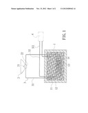
[0013] FIG. 2 is a schematic drawing showing an embodiment in use according to the present invention.
DETAILED DESCRIPTION OF THE PREFERRED EMBODIMENT
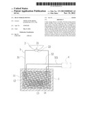
[0014] Refer to FIG. 1 a heat storage device of the present invention includes a heat storage tank 1, a heat source 2 and a heat conduction unit 3.
[0015] The heat storage tank 1 can be a container or other device that is easily to get. The wall of the heat storage tank 1 includes an outer wall and an inner wall while a sandwich space 11 is formed between the inner wall and the outer wall. The space 11 is filled with heat insulation material 12. The heat insulation material 12 can be one of the following: calcium silicate board, calcium oxide or construction waste with heat insulation property, or their combinations. The heat storage tank 1 further includes a receiving space 13 for mounting heat storage material 14. The heat storage material 14 is selected from one of the following: sand and crushed stone, including land sand and sea sand, whose diameter is less than 30 centimeters, brick clay, cement, cinder, shell or their combinations. Except the space occupied by a heat conductor 31 and a heat exchanger 32, the heat storage material 14 is filled in the residual space of the receiving space 13 so as to cover the heat conductor 31 and the heat exchanger 32 well.
[0016] The heat source 2 is a light gathering cup including a concave surface and an upward opening. A connection part 22 is arranged under a light gathering point 21 on a center of the light gathering cup.
[0017] The heat conduction unit 3 includes the heat conductor 31 and the heat exchanger 32, both are tubes with high temperature resistance, high pressure resistance and corrosion resistance. Each tube is filled with a fluid. Moreover, the heat conductor 31 is connected to the connection part 22 of the heat source 2. Furthermore, a part of the heat conductor 31 is extending into the receiving space 13 of the heat storage tank 1 so that the part of the heat conductor 31 and a part of the heat exchanger 32 in the receiving space 13 are contacted with and twisted around each other. Another part of the heat exchanger 32 extending out of the heat storage tank 1 forms a heat supply segment 321 which is connected to an object to be heated 4.
[0018] In use, as shown in FIG. 2, the heat source 2 is arranged at outdoors where sunlight shines. The sunlight is reflected by the curved surface of the heat source 2 and is focused on the central light gathering point 21 of the heat source 2. Then the focused solar energy is transmitted to the heat conductor 31 through the connection part 22 of the heat source 2 connected to the heat conductor 31 so as to heat the fluid inside the heat conductor 31. Next the heated fluid inside the heat conductor 31 moves therealong and flows into the heat storage tank 1 so that heat exchange occurs between the fluid in the heat conductor 31 and a fluid in the heat exchanger 32 twisted around each other. After receiving heat from the fluid in the heat conductor 31, the temperature of the fluid inside the heat exchanger 32 is increased. Thus the fluid inside the heat exchanger 32 is flowing therealong into the heat supply segment 321 that is in connected to the object to be heated 4. Finally, the object 4 is heated. Thereby the heat source 2 absorbs solar energy so as to heat the fluid in the heat conductor 31. Then heat exchange occurs between the fluid in the heat conductor 31 and a fluid inside the heat exchanger 32. The temperature of the fluid inside the heat exchanger 32 is increased to heat the object 4. During these recycling processes, there is no electricity used. Therefore the heavy burden caused by high-cost electricity for heating the object 4 is reduced, the energy is saved and the carbon dioxide emission is down.
[0019] In addition, the receiving space 13 of the heat storage tank 1 is filled by the heat storage material 14. And the heat conductor 31 and the heat exchanger 32 are covered by the storage material 14. Thus the heat is concentrated. Moreover, the heat insulation material 12 between the walls of the heat storage tank 1 provides a great reduction of heat transfer through conduction so as to maintain the receiving space 13 of the heat storage tank 1 in a high-temperature state. Due to the coverage of the storage material 14 and reduction of heat transfer by the heat insulation material 12, the heat is transferred from the fluid inside the heat conductor 31 to the fluid in the heat exchanger 32. The heat storage tank 1 can be a vacant container. By using material from local sources, the heat storage material 14 can be local sand and crushed stone, construction material such as brick clay, cement, etc, or waste such as cinder, shell, etc. Thus the manufacturing cost of the heat storage device is reduced. Moreover, both the construction material and the waste are used again. The recycling of material and waste reduces pollutants and improves the environment.
[0020] The heat storage material 14 of the heat storage device according to the present invention is not limited to be construction material or waste. It can be new material with heat storage property or used material with heat storage property.
[0021] In summary, the present invention has following advantages:
1. The heat storage tank of the heat storage device according to the present invention is a vacant container while the heat storage material is construction material such as sand and crushed stone, brick clay, cement, etc. or waste such as cinder, shell, etc. Thus the waste is recycled or reused again. This not only reduces manufacturing cost of the heat storage device but also makes good use of the material. The pollutants are reduced and the environment is improved. 2. A vacant container from local sources can be used as the heat storage tank of the heat storage device according to the present invention while both the heat storage material and the heat insulation material can be made from waste material generated by construction activities. Thus there is no need to transport the heat storage tank, and material required for the heat storage material and the heat insulation material to the location at which the heat storage device is set up. The transportation cost is saved. 3. The heat storage device of the present invention can store and convert solar energy to heat energy effectively so as to heat objects. Thus the heat storage device can replace the heating pattern used now which heats objects by energy coming from electricity. This helps ease the burden caused by the expensive electricity, saves energy, reduces carbon dioxide emission and protects the environment. 4. In the present invention, the heat storage tank that reduces heat transfer well is use as an environment facilitating heat exchange between the heat conductor absorbed solar energy and objects to be heated. Thereby the solar energy is used to heat the object effectively and efficiently.
[0022] Additional advantages and modifications will readily occur to those skilled in the art. Therefore, the invention in its broader aspects is not limited to the specific details, and representative devices shown and described herein. Accordingly, various modifications may be made without departing from the spirit or scope of the general inventive concept as defined by the appended claims and their equivalent.
User Contributions:
Comment about this patent or add new information about this topic:
Images included with this patent application:
 |  |
 |
| Similar patent applications: | |
| Date | Title |
|---|---|
| 2010-08-26 | Thermal energy storage device |
| 2010-02-11 | Heat storage and transfer system |
| 2012-01-12 | Thermal signaling or marking device |
| 2009-06-25 | Heat reclaimer device |
| 2012-07-19 | Solar heater system for domestics waters |
| New patent applications in this class: | |
| Date | Title |
|---|---|
| 2016-07-14 | Energy system |
| 2015-10-15 | Heat storage apparatus |
| 2015-05-21 | Heat storage tank with improved thermal stratification |
| 2014-10-30 | Mining system with sustainable energy reservoir legacy |
| 2014-10-09 | Solar heat collection and storage system |
| Top Inventors for class "Stoves and furnaces" | |
| Rank | Inventor's name |
|---|---|
| 1 | Paul Bryan Cadima |
| 2 | David Deng |
| 3 | Andrew Plotkin |
| 4 | Peter Emery Von Behrens |
| 5 | Derek W. Schrock |