Patent application title: GOLF BALL
Inventors:
Katsunori Sato (Chichibushi, JP)
Assignees:
BRIDGESTONE SPORTS CO., LTD.
IPC8 Class: AA63B3714FI
USPC Class:
473379
Class name: Ball particular cover (e.g., size, material, dimple pattern, etc.) icosahedral dimple pattern
Publication date: 2012-11-01
Patent application number: 20120277032
Abstract:
A golf ball has a plurality of dimples, wherein: (1) the dimples have a
peripheral edge with a radius of curvature R from 0.5 mm to 2.5 mm; (2)
the surface coverage SR of the dimples, expressed as a percentage of the
surface area of a hypothetical sphere representing the ball if it had no
dimples, is from 60% to 74%; and (3) the ratio ER of a collective number
of dimples RA having a radius of curvature R to diameter D ratio (R/D) of
at least 20%, divided by a total number of dimples N on the surface of
the ball, is from 15% to 95%. This combination of features enables damage
to the paint film on the surface of the ball to be minimized, improves
the durability of markings on the surface of the ball, and prevents a
decline in ball performance.Claims:
1. A golf ball comprising a spherical surface on which a plurality of
dimples are formed, wherein the dimples satisfy conditions (1) to (3)
below: (1) the dimples have a peripheral edge provided with a roundness
represented by a radius of curvature R of from 0.5 mm to 2.5 mm; (2) the
surface coverage SR of the dimples, which is the sum of individual dimple
surface areas, each defined by a flat plane circumscribed by an edge of
the dimple, expressed as a percentage of the surface area of a
hypothetical sphere representing the ball were the ball to have no
dimples on the surface thereof, is from 60% to 74%; and (3) the ratio ER
of a collective number of dimples RA having a radius of curvature R to
diameter D ratio (R/D) of at least 20%, divided by a total number of
dimples N on the surface of the ball, is from 15% to 95%.
2. The golf ball of claim 1 which further satisfies condition (4) below: (4) the ball has thereon a plurality of dimple types of differing diameter, and the ratio DER of a combined number of dimples DE obtained by adding together dimples having an own diameter and an own radius of curvature larger than or equal to a radius of curvature of dimples of larger diameter than said own diameter plus dimples of a type having a largest diameter, divided by the total number of dimples N on the surface of the ball, is at least 80%.
3. The golf ball of claim 1 which further satisfies condition (5) below: (5) the total number of dimples N is not more than 380.
4. The golf ball of claim 1 which further satisfies condition (6) below: (6) each dimple has a spatial volume below a flat plane circumscribed by an edge of the dimple, and the sum of the dimple spatial volumes, expressed as a percentage (VR) of the volume of a hypothetical sphere representing the ball were the ball to have no dimples on the surface thereof, is from 0.8% to 1.7%.
5. The golf ball of claim 1, wherein the dimples are spread out over the spherical surface of the ball in a configuration selected from the group consisting of icosahedral configurations, dodecahedral configurations, octahedral configurations, configurations having three-fold symmetry, and configurations having five-fold symmetry.
Description:
CROSS-REFERENCE TO RELATED APPLICATION
[0001] This non-provisional application claims priority under 35 U.S.C. §119(a) on Patent Application No. 2011-099936 filed in Japan on Apr. 27, 2011, the entire contents of which are hereby incorporated by reference.
BACKGROUND OF THE INVENTION
[0002] 1. Field of the Invention
[0003] The present invention relates to a golf ball having a plurality of dimples on the surface thereof. More specifically, the invention relates to a golf ball which minimizes damage to the dimple edges, thereby improving durability.
[0004] 2. Prior Art
[0005] Golf balls of various types are known, including one-piece balls composed of a single layer of hard rubber; solid balls composed of a solid core of hard rubber around which has been formed, either directly or over an intervening intermediate layer, a cover composed primarily of an ionomer resin or the like; and wound balls obtained by winding a rubber thread around a center ball to form a wound core, then forming a balata cover over the core.
[0006] All of these golf balls typically have a plurality of dimples provided over the entire spherical surface of the ball. In addition, markings such as a brand name or player number are printed onto the surface of the ball on which these dimples have been formed, following which a coating (typically clear paint) is applied to protect the cover material and improve the outer appearance, thereby giving a finished ball.
[0007] However, when a golf ball is struck with a metal clubhead, it is subjected to a very strong impact. At the same time, owing to the loft angle of the club, powerful frictional forces act on the surface of the ball. As a result of these effects, the ball's surface tends to incur damage. Moreover, on certain shots such as bunker shots, sand caught between the face of the clubhead and the ball often damages the ball surface even further.
[0008] As a result, the paint film that has been formed on the surface of the golf ball becomes damaged and worn or peels, causing detrimental effects to the markings printed on the ball's surface, such as skipping, gaps and blurring, which tends to lower the commercial value of the ball. In addition, local peeling or loss of the paint film sometimes lowers the expected ball performance.
[0009] Also, in the case of practice golf balls intended for use at such places as driving ranges, markings which indicate the ball to be a range ball are printed on the ball. However, because practice golf balls are furnished for repeated hitting over a long period of time, durability is a key feature of such balls. Improvements in the durability of such markings are also keenly desired.
[0010] Prior-art publications relating to the present invention include JP-A 48-063835, JP-A 01-268578, JP-A 02-045074, JP-A 2000-279553, JP-A 2004-073524, JP-A 2005-319292, JP-A 2007-136173 and JP-A 2007-190382.
[0011] In view of the foregoing, it is an object of the present invention to minimize damage to the paint film on the surface of a golf ball and effectively improve the durability of markings printed on the surface of the ball, and also to prevent a decline in ball performance on account of damage to the paint film.
SUMMARY OF THE INVENTION
[0012] After noticing that damage to the paint film on the surface of a golf ball tends to occur most readily at the edge areas of the dimples, I have discovered that forming the dimple edges so as to be smooth effectively suppresses damage to the paint film, especially peeling of the film, thereby improving the durability of markings, and moreover helps prevent a decline in ball performance on account of damage to the paint film. Further investigations on how to reliably achieve these aims without sacrificing desirable features of the ball such as the flight performance, and also on the radius of curvature (R) at the dimple edges, the relationship between the dimple size (diameter D) and the radius of curvature R, and the relationship between the total number of dimples N on the surface of the ball and the radius of curvature R ultimately led to the present invention.
[0013] Accordingly, the present invention provides a golf ball having a spherical surface on which a plurality of dimples are formed, wherein the dimples satisfy conditions (1) to (3) below:
[0014] (1) the dimples have a peripheral edge provided with a roundness represented by a radius of curvature R of from 0.5 mm to 2.5 mm;
[0015] (2) the surface coverage SR of the dimples, which is the sum of individual dimple surface areas, each defined by a flat plane circumscribed by an edge of the dimple, expressed as a percentage of the surface area of a hypothetical sphere representing the ball were the ball to have no dimples on the surface thereof, is from 60% to 74%; and
[0016] (3) the ratio ER of a collective number of dimples RA having a radius of curvature R to diameter D ratio (R/D) of at least 20%, divided by a total number of dimples N on the surface of the ball, is from 15% to 95%.
[0017] The golf ball may satisfy also condition (4) below:
[0018] (4) the ball has thereon a plurality of dimple types of differing diameter, and the ratio DER of a combined number of dimples DE obtained by adding together dimples having an own diameter and an own radius of curvature larger than or equal to a radius of curvature of dimples of larger diameter than the own diameter plus dimples of a type having a largest diameter, divided by the total number of dimples N on the surface of the ball, is at least 80%.
[0019] The golf ball may satisfy also condition (5) below:
[0020] (5) the total number of dimples N is not more than 380.
[0021] The golf ball may satisfy also condition (6) below:
[0022] (6) each dimple has a spatial volume below a flat plane circumscribed by an edge of the dimple, and the sum of the dimple spatial volumes, expressed as a percentage (VR) of the volume of a hypothetical sphere representing the ball were the ball to have no dimples on the surface thereof, is from 0.8% to 1.7%.
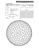
[0023] In the golf ball of the invention, the dimples may be spread out over the spherical surface of the ball in a configuration selected from the group consisting of icosahedral configurations, dodecahedral configurations, octahedral configurations, configurations having three-fold symmetry, and configurations having five-fold symmetry.
[0024] The golf ball of the invention, by optimizing the dimple edges, effectively suppresses damage to the paint film that has been formed on the surface of the ball, particularly peeling of the film, minimizes damage to markings that have been printed onto the ball surface, and moreover prevents a decrease in performance on account of damage to the paint film.
BRIEF DESCRIPTION OF THE DIAGRAMS
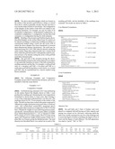
[0025] FIG. 1 is a schematic diagram showing a dimple cross-section.
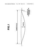
[0026] FIG. 2A is a top view and FIG. 2B is a side view showing an example of a dimple configuration.
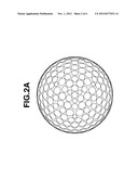
[0027] FIG. 3 is a top view showing the markings that were placed on the golf balls fabricated in the examples and the comparative examples.
DETAILED DESCRIPTION OF THE INVENTION
[0028] The objects, features and advantages of the invention will become more apparent from the following detailed description, taken in conjunction with the foregoing diagrams.
[0029] Referring to FIG. 1, the golf ball of the invention has a spherical surface on which a plurality of dimples are formed, which dimples have a peripheral edge provided with a roundness represented by a radius of curvature R of from 0.5 mm to 2.5 mm (condition (1)).
[0030] As noted above, the radius of curvature R is from 0.5 mm to 2.5 mm, with the lower limit being preferably 0.6 mm, and more preferably 0.7 mm, and the upper limit being preferably 1.8 mm, and more preferably 1.5 mm.
[0031] Here, the dimples provided on the surface of the inventive golf ball, although not subject to any particular limitation, are formed as dimples of preferably three or more types, and more preferably five or more types, of differing diameter D. In this case, the diameter D of the dimples, although not subject to any particular limitation, is preferably in a range of from 1.5 mm to 7 mm, with the lower limit being more preferably 1.8 mm and the upper limit being more preferably 6.5 mm. The depth of the dimples, although not subject to any particular limitation, is preferably in a range of from 0.05 mm to 0.35 mm, with the lower limit being more preferably 0.1 mm and the upper limit being more preferably 0.3 mm, and even more preferably 0.25 mm. The total number of dimples N on the surface of the ball, although not subject to any particular limitation, is preferably not more than 380 (condition (5)), and more preferably not more than 350. The total number of dimples N is even more preferably in a range of from 220 to 340.
[0032] In the present invention, the dimples must be formed in such a way that the surface coverage SR of the dimples, which is the sum of individual dimple surface areas, each defined by a flat plane circumscribed by an edge of the dimple (dash-dot line in FIG. 1), expressed as a percentage of the surface area of a hypothetical sphere representing the ball were the ball to have no dimples on the surface thereof (broken line in FIG. 1), is in a range of from 60% to 74% (condition (2)). At a surface coverage SR greater than 74%, the intervals between neighboring dimples become too narrow, which makes it difficult to provide the dimple edges with a roundness having the radius of curvature R specified in above condition (1). On the other hand, at a surface coverage SR below 60%, the aerodynamic performance decreases, as a result of which the distance traveled by the ball will decrease. The surface coverage SR has a lower limit of preferably 65%, and more preferably 68%, and an upper limit of preferably 73%.
[0033] Moreover, in the invention, the dimples must be formed in such a way that the ratio ER of a collective number of dimples RA having a radius of curvature R to diameter D ratio (R/D) of at least 20%, divided by the total number of dimples N on the surface of the ball, is in a range of from 15% to 95% (condition (3)). Here, the ratio R/D is expressed as a percentage (R/D×100%), a larger value indicating a dimple in which the rounded part of the dimple accounts for a larger proportion of the dimple size and which has a smoother cross-sectional shape. The ratio ER indicates the number of such smooth dimples as a proportion of the total number of dimples; by setting ER in a range of from 15% to 95%, damage to the paint film at dimple edges can be effectively suppressed. The upper limit in the ratio R/D, although not subject to any particular limitation, is preferably not more than 60%, and more preferably not more than 40%. The lower limit in the ratio ER is preferably 20%, and more preferably 25%, and the upper limit is preferably 90%, more preferably 85%, and even more preferably 70%.
[0034] Also, in cases where the ball has a plurality of dimple types of differing diameter D thereon, although not subject to any particular limitation in the invention, it is preferable for the ratio DER of a combined number of dimples DE obtained by adding together dimples having an own diameter and an own radius of curvature larger than or equal to a radius of curvature of dimples of larger diameter than the own diameter plus dimples of a type having a largest diameter, divided by the total number of dimples N on the surface of the ball, to be at least 80% (condition (4)).
[0035] Generally, at a fixed dimple depth (see FIG. 1), the radius of curvature R representing the roundness provided to the peripheral edges of the dimples is smaller at smaller dimple diameters D. However, by employing such means as adjusting the depth so as to set the radius of curvature R representing the roundness of the peripheral edge to be as large as possible even in dimples having a small diameter D, dimples having a smooth cross-sectional shape are formed, and by setting the above ratio DER to at least 80%, the proportion of such smooth dimples is increased, more effectively suppressing damage to the paint film. The ratio DER is more preferably at least 85%, even more preferably at least 90%, and most preferably at least 93%. The upper limit in the ratio DER is 100%.
[0036] In the golf ball of the invention, although not subject to any particular limitation, the dimples are preferably formed such that each dimple has a spatial volume below a flat plane (dash-dot line in FIG. 1) circumscribed by an edge of the dimple, and the sum of the dimple spatial volumes, expressed as a percentage (VR) of the volume of a hypothetical sphere (broken line in FIG. 1) representing the ball were the ball to have no dimples on the surface thereof, is in a range of from 0.8% to 1.7% (condition (6)).
[0037] The reason for doing so is as follows. Providing the peripheral edges of the dimples with roundness generally tends to confer flight characteristics which increase the height of the trajectory. Hence, setting the volume ratio VR to a high value as described above helps the ball to maintain a stable trajectory. The lower limit in the value VR is more preferably 0.83%, even more preferably 0.85%, and most preferably 0.86%. The upper limit in the value VR is more preferably 1.5%, even more preferably 1.3%, and most preferably 1.2%.
[0038] The above-described dimples which are formed on the surface of the inventive golf ball have a shape, as viewed from above, which is generally circular, but may also have a non-circular shape formed of curved lines. The configuration of the dimples on the surface of the ball is not subject to any particular limitation. For example, use may be made of an icosahedral configuration, a dodecahedral configuration, an octahedral configuration, a configuration having three-fold symmetry or a configuration having five-fold symmetry.
[0039] Molding of the inventive golf ball having the above-described dimples on the surface thereof may be carried out by injection molding or compression molding according to a conventional method using a mold onto the cavity wall of which the above dimples have been transferred as reversed three-dimensional features (projections). The mold may be fabricated using 3D CAD/CAM, either by directly cutting the entire surface shape three-dimensionally into a master mold from which the golf ball mold is subsequently made by pattern reversal, or by directly cutting the cavity of the golf ball mold three-dimensionally.
[0040] The golf ball of the invention having the above-described dimples formed on the surface thereof is not subject to any particular limitation in terms of the ball construction, molding materials and the like. For example, a solid golf ball such as a one-piece golf ball, a two-piece golf ball or a multi-piece golf ball having three or more layers, or a wound golf ball, may be manufactured by a known method using known materials.
EXAMPLES
[0041] The following Examples and Comparative Examples are provided to illustrate the invention, and are not intended to limit the scope thereof.
Examples 1 to 3
Comparative Example
[0042] Golf balls having a diameter of 42.7 mm and bearing on the surface thereof the dimples shown in Table 1 were produced by molding and vulcanizing the core compositions formulated as shown below to form cores, then forming a cover of the composition indicated below over the cores. The markings shown in FIG. 3 were printed on the surface of the balls. The ball was then clear-coated with a paint composed of 100 parts by weight of polyester resin (acid value, 6; hydroxyl value, 168) (solids)/butyl acetate/PMA (propylene glycol monomethyl ether acetate) in a weight ratio of 70/15/15 as the base; 150 parts by weight of a non-yellowing polyisocyanate, specifically a hexamethylene diisocyanate adduct (available from Takeda Pharmaceutical Co., Ltd. as Takenate D-160N; NCO content, 8.5 wt %; solids content, 50 wt %) as the curing agent; and 150 parts by weight of butyl acetate. In this way, a paint film was formed, giving the finished product. The sand abrasion test described below was carried out on each of the resulting golf balls, and the durability of the markings was evaluated. The results are shown in Table 1.
Core Material Formulation
TABLE-US-00001 [0043] BR01 95 parts by weight (a butadiene rubber synthesized with a nickel catalyst, available from JSR Corporation) IR2200 5 parts by weight (an isoprene rubber, available from JSR Corporation) Percumyl D 1.07 parts by weight (an organic peroxide available from NOF Corporation) Zinc oxide 23 parts by weight (available from Sakai Chemical Co., Ltd.) Antioxidant 0.2 part by weight ("Nocrac NS-6," available from Ouchi Shinko Chemical Industry Co., Ltd.) Methacrylic acid 22.5 parts by weight (available from Asada Chemical Industry Co., Ltd.)
Cover Formulation
TABLE-US-00002 [0044] Pandex T8195 100 parts by weight (a thermoplastic polyurethane elastomer available from Dainippon Ink & Chemicals, Inc.) Titanium dioxide 3.5 parts by weight (available under the trade name "Tipaque R550" from Ishihara Sangyo Kaisha, Ltd.) Polyethylene wax 1.5 parts by weight (available under the trade name "Sanwax 161P" from Sanyo Chemical Industries, Ltd.)
Abrasion Test
[0045] Ten golf balls and 3 liters of bunker sand were placed in a magnetic ball mill having an 8 liter capacity and mixing was carried out for 144 hours, following which the balls were visually examined for any loss of the markings and to assess the degree of surface scratching, the degree of loss of luster and the degree of sand adhesion. The ball appearance was rated as "good," "fair" or "NG."
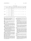
TABLE-US-00003 TABLE 1 Diameter N RA DE Durability Dimple D Depth R R/D (num- (num- ER (num- DER SR VR Configu- of No. Number (mm) (mm) (mm) ratio ber) ber) (%) ber) (%) (%) (%) ration markings Example 1 1 24 4.4 0.182 0.75 17 338 102 30 330 98 72 0.86 FIG. 2 good 2 204 4.2 0.175 0.8 19 3 66 3.6 0.165 0.8 22 4 12 2.7 0.135 0.9 33 5 24 2.5 0.105 0.9 36 6 8 3.4 0.145 0.6 18 Example 2 1 24 4.4 0.207 0.7 16 338 102 30 330 98 72 0.99 FIG. 2 good 2 204 4.2 0.200 0.7 17 3 66 3.6 0.190 0.8 22 4 12 2.7 0.160 0.85 31 5 24 2.5 0.130 0.85 34 6 8 3.4 0.145 0.55 16 Example 3 1 24 4.4 0.237 0.65 15 338 102 30 330 98 72 1.14 FIG. 2 fair 2 204 4.2 0.230 0.65 15 3 66 3.6 0.220 0.75 21 4 12 2.7 0.190 0.8 30 5 24 2.5 0.160 0.8 32 6 8 3.4 0.145 0.45 13 Comparative 1 24 4.4 0.216 0.5 11 338 36 11 306 91 72 0.99 FIG. 2 NG Example 1 2 204 4.2 0.209 0.5 12 3 66 3.6 0.194 0.6 17 4 12 2.7 0.151 0.6 22 5 24 2.5 0.116 0.5 20 6 8 3.4 0.160 0.5 15
[0046] The abbreviations and symbols relating to dimples which appear in Table 1 are explained below. [0047] R: Radius of curvature representing roundness provided at peripheral edge of a dimple [0048] R/D ratio: Ratio of radius of curvature R to diameter D [0049] N: Total number of dimples on surface of ball [0050] RA: Collective number of dimples having an R/D ratio of at least 20% [0051] ER: Ratio of RA to total number of dimples N [0052] DE: Sum of number of dimples having an own diameter and an own radius of curvature larger than or equal to a radius of curvature of dimples of larger diameter than the own diameter, plus number of dimples of a type having a largest diameter [0053] DER: Ratio of DE to total number of dimples N [0054] SR: Sum of individual dimple surface areas, each defined by a flat plane circumscribed by an edge of the dimple, expressed as a percentage of the surface area of a hypothetical sphere representing the ball were the ball to have no dimples on the surface thereof [0055] VR: Sum of individual dimple spatial volumes, each formed below a flat plane circumscribed by an edge of the dimple, expressed as a percentage of the volume of a hypothetical sphere representing the ball were the ball to have no dimples on the surface thereof
[0056] As is apparent from Table 1, the golf balls of Examples 1 to 3 on which dimples according to the present invention had been formed were able to minimize damage to the surface coat and effectively improve the durability of markings printed on the ball surface.
[0057] Japanese Patent Application No. 2011-099936 is incorporated herein by reference.
[0058] Although some preferred embodiments have been described, many modifications and variations may be made thereto in light of the above teachings. It is therefore to be understood that the invention may be practiced otherwise than as specifically described without departing from the scope of the appended claims.
User Contributions:
Comment about this patent or add new information about this topic:
Images included with this patent application:
 |  |
 |  |
 |  |
 |  |
| New patent applications in this class: | |
| Date | Title |
|---|---|
| 2016-02-25 | Golf ball having non-planar parting line with non-circular dimples |
| 2013-10-31 | Dimple arrangement on the surface of a golf ball and the golf ball thereof |
| 2013-10-10 | Non-circular dimple golf ball |
| 2013-03-14 | Dimple patterns for golf balls |
| 2013-02-14 | Golf ball having non-concentric parting line |
| New patent applications from these inventors: | |
| Date | Title |
|---|---|
| 2020-04-16 | Golf ball |
| 2020-04-16 | Golf ball |
| 2020-03-19 | Multi-piece solid golf ball |
| 2017-05-18 | Multi-piece solid golf ball |
| 2014-03-13 | Golf ball |
| Top Inventors for class "Games using tangible projectile" | |
| Rank | Inventor's name |
|---|---|
| 1 | Michael J. Sullivan |
| 2 | Brian Comeau |
| 3 | Derek A. Ladd |
| 4 | David A. Bulpett |
| 5 | Mark L. Binette |