Patent application title: Boat Ramp Buddy
Inventors:
Charles Guetersloh (Murphysboro, IL, US)
IPC8 Class: AB62D6308FI
USPC Class:
280762
Class name: Wheeled attachment exterior
Publication date: 2012-11-01
Patent application number: 20120274055
Abstract:
The device sometimes called a boat ramp buddy is a generally triangular
device that attaches to a trailer frame. The device is used to help the
trailer skid across uneven or washed out boat ramps or uneven ground so
as not to damage the trailer itself or remove its wheels.Claims:
1. A generally triangular device placed on a trailer frame in front of a
trailer wheel comprising: a first lateral side and a second lateral side
connected by a back perimeter side having a drain opening, a bottom
perimeter side, a top perimeter side, and a rounded junction.
2. The device in claim 1 where the first and second lateral sides have one or more holes.
3. The device in claim 1 where the top perimeter side has an opening allowing a spring shackle to go through.
4. The device in claim 1 where the back perimeter side has a spring shackle opening.
5. The device in claim 1 where the top perimeter side has a first bolt hole near the point where the top perimeter side, the bottom perimeter side, and the first lateral side meet; a second bolt hole near the point where the top perimeter side, the back perimeter side, and the first lateral side meet; a third bolt hole near the point where the top perimeter side, the bottom perimeter side, and the second lateral side meet; and a fourth bolt hole near the point where the top perimeter side, the back perimeter side, and the second lateral side meet.
6. The device in claim 1 where a friction plate is above the trailer frame and attached by a series of bolts in the first through fourth bolt holes
7. The device in claim 1 where the top perimeter side is welded to the trailer frame.
8. A generally triangular device comprising: a central member connected in perpendicular fashion to a generally triangular shape formed by connecting a back member, a bottom member, and a top member with back member and bottom member forming a rounded junction where they connect.
9. The device in claim 8 where the device is connected by welding the top member to the trailer frame.
10. The device in claim 8 where the device has one or more reinforcement strips with a length greater than width attached to the top member, on one side to the central member, and to the bottom member.
11. The device in claim 8 where the top member has a first bolt hole near the point where the top member, the bottom member, and the central member meet on the first side of the central member; a second bolt hole near the point where the top member, the bottom member, and the central member meet on the second side of the central member; a third bolt hole near the point where the top member, the back member, and the central member meet on the second side of the central member; and a fourth bolt hole near the point where the top member, the back member, and the central member meet on the second side of the central member.
12. The device in claim 8 where a friction plate is above the trailer frame and attached by a series of bolts in the first through fourth bolt holes.
Description:
CROSS REFERENCE TO RELATED APPLICATIONS
[0001] This application claims the benefit of U.S. Provisional Application Ser. No. 61/479,890 filed by Guetersloh on Apr. 28, 2010 and entitled "Boat Ramp Buddy", which is incorporated herein by reference.
FIELD OF INVENTION
[0002] The invention relates to equipment used on a trailer that can be used for a boat or a trailer that is used to haul items including but not limited to construction materials, household items, other vehicles and other items.
BACKGROUND OF THE INVENTION
[0003] Boats are hauled to a body of water such as a lake or river on a trailer pulled by a truck or car. Then they are backed down a ramp into the water. The ramps can be made of asphalt, concrete, or various consistencies of soil, rock, or sand. The boat and the trailer have to go into the water before the boat can be removed. Thus, the bottom end of the ramp is exposed to water and currents in the water. Over time, the boat ramp can erode. Because it is underwater, it is not visible to the person putting their boat into the water or taking it out. When getting a trailer out of the water, the wheels will often get stuck on an eroded ramp. While attempting to get the trailer out of the water, the owner will exert force on the boat trailer causing the axle to be damaged or removed from the trailer. Additionally, other parts of trailer and boat could be damaged. Trailers used on land exclusively also have the problem of getting stuck on uneven ground.
SUMMARY OF THE INVENTION
[0004] The present invention is a generally triangular device that can be made of any material that is strong enough to withstand the force of a trailer moving across a ramp. Examples of materials can be polymers, high density plastics, iron, steel, and aluminum. The device is attached to the bottom of the frame just in front of the wheels on both sides of the frame.
BRIEF DESCRIPTION OF DRAWINGS
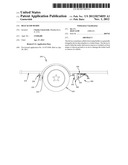
[0005] FIG. 1 is a side view of a trailer with the device attached
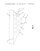
[0006] FIG. 2 is a close-up side view of the device attached to a trailer.
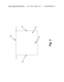
[0007] FIG. 3 is a rear view of the device.
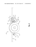
[0008] FIG. 4 is a side view of the trailer and the device bolted onto the trailer.
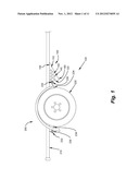
[0009] FIG. 5 is a close-up side view of the device bolted on the trailer.
[0010] FIG. 6 is a rear view of the device bolted on the trailer.
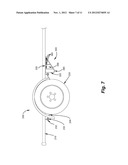
[0011] FIG. 7 is a side vide of the device attached to the trailer.
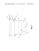
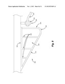
[0012] FIG. 8 is a close-up side view of the device attached to the trailer.
[0013] FIG. 9 is a rear view of the device.
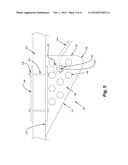
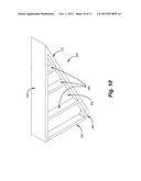
[0014] FIG. 10 is an orthogonal view of the device.
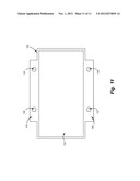
[0015] FIG. 11 is a top view of the device.
DETAILED DESCRIPTION OF THE INVENTION
[0016] The device 100, 300 sometimes called a boat ramp buddy is a generally triangular device that attaches to a trailer frame 210. The device 100, 300 is used to help the trailer 200 skid across uneven or washed out boat ramps or uneven ground. The material of the device 100, 300 is strong enough to withstand skidding across the boat ramp or uneven ground. This device 100, 300 protects the trailer wheels 220 and axle from being torn from the trailer frame.
[0017] In one embodiment of the device as in FIGS. 1-6, the device 100 has a first lateral side 150 and a second lateral side 160 that are connected on three sides: a back perimeter side 120, a bottom perimeter side 110 and a top perimeter side 130. The top perimeter side 130 is the connection point for the trailer frame 210. The top perimeter side 130 is generally parallel to the trailer frame. The top perimeter side 130 in FIG. 11 when it has an top perimeter side opening 132 it will also have a first and second lateral flanges 170, 180 with four bolt holes: A first bolt hole 131 near the point where the top perimeter side 130, the bottom perimeter side 110 and the first lateral side 150 meet, a second bolt hole 133 near the point where the top perimeter side 130, the back perimeter side 120 and the first lateral side 150 meet, a third bolt hole 135 near the point where the top perimeter side 130, the bottom perimeter side 110 and the second lateral side 160 meet, and a fourth bolt hole 137 near the point where the top perimeter side 130, the back perimeter side 120 and the second lateral side 160 meet. The first and second lateral flanges 170, 180 extend from the top perimeter side 130 in a perpendicular fashion to the first and second lateral sides 150, 160.
[0018] Above the frame 210 can be a friction plate 138. The purpose of the friction plate 138 is to have four bolt holes that match up with the four bolt holes 131, 133, 135, and 137 on the top perimeter side. A bolt 134 will be inserted through those bolt holes and the friction plate 138 will prevent forward and backward movement of the device 100. The bolts 134 are held on by nuts 136. The friction plate 138 is also made of a hard material, which could be steel, iron, high density plastics, polymers, or aluminum.
[0019] The first and second lateral sides 150, 160 can include one or more holes 140 as long as the lateral sides 150, 160 are strong enough to withstand the force of the trailer frame 210 skidding across the ramp. But the first and second lateral side 150, 160 can be without holes 140. The first and second lateral sides 150, 160 are as thin as possible but still allow for strength to not bend when used on uneven ground.
[0020] The back perimeter side 120 can include a spring shackle opening 124 to allow the spring shackle 230 to go through to the bottom of the trailer frame. The spring shackle 230 has two parts a spring 234 and an attachment assembly 232. The spring shackle may have an optional spring bolt 236 through a hole 140 to help hold the spring 234 in place. Also below the spring shackle opening 124 is a drain hole 122. The purpose of the drain hole 122 is to allow any water that accumulates to drain out. When the trailer 200 is put in the water, water can get inside the device 100.
[0021] The back perimeter side 120 and a bottom perimeter side 110 are joined at round junction 190. The round junction 190, 340 can be more rounded than shown in the figures so that the device 100, 300 can facilitate the trailer going backward or forward over dropoffs or step-ups in the water or on land.
[0022] The device 100 could be welded onto the frame instead of bolted or it could be attached in a number of different ways.
[0023] The second embodiment of the device 300 in FIGS. 7-10 is a top member 330, a bottom member 310, a central member 350 and a back member 320 connected together in a generally triangular shape. The bottom member 310 and the back member 320 are brought together in a circular shape. The central member 350 meets the back member 320, the bottom member 310 and the top member 330 in a perpendicular fashion to form what looks like an I-beam. The central member 350 can have one or more reinforcement strips 360 that have a length greater than the width. One end of the reinforcement strip 360 is attached to the top member 330 on one side of the central member 350 and on the second end to the bottom member 310. The reinforcement strips 360 can be omitted if the material is sufficiently strong that it does not require reinforcement.
User Contributions:
Comment about this patent or add new information about this topic:
| People who visited this patent also read: | |
| Patent application number | Title |
|---|---|
| 20210198493 | SILICATE-COATED BODY |
| 20210198492 | COLORING COMPOSITION AND METHOD FOR PRODUCING COLOR FILTER FOR SOLID-STATE IMAGING ELEMENT |
| 20210198491 | ASPHALT COMPOSITION COMPRISING A MIXTURE OF AN ISOCYANATE AND A POLYMER AS PERFORMANCE ADDITIVES |
| 20210198490 | CURABLE WHITE SILICONE FORMULATION, A REFLECTIVE MATERIAL FOR OPTICAL SEMICONDUCTOR MODULE, AND OPTICAL SEMICONDUCTOR DEVICE |
| 20210198489 | ORGANOPOLYSILOXANE COMPOSITION |
Images included with this patent application:
 |  |
 |  |
 |  |
 |  |
 |  |
 |  |
| New patent applications in this class: | |
| Date | Title |
|---|---|
| 2016-02-25 | Coupling part |
| 2014-11-13 | Marking device for a personal mobility vehicle |
| 2014-10-23 | Bicycle wind resistance trainer |
| 2014-08-21 | Counterweight assembly for a self-propelled derrick rig assembly |
| 2014-06-05 | External airbag apparatus |
| Top Inventors for class "Land vehicles" | |
| Rank | Inventor's name |
|---|---|
| 1 | Osamu Fukawatase |
| 2 | Christopher P. D'Aluisio |
| 3 | Richard W. Mccoy |
| 4 | Jun Yeol Choi |
| 5 | Yusuke Fujiwara |