Patent application title: Method and Apparatus for Cooling and/or Deep-Freezing Products, Especially Food Products, Implementing the Injection of Two Cryogenic Liquids
Inventors:
Franck Cousin (Saint Brevin Les Pins, FR)
Nicolas Fachon (Marquise, FR)
Willy Frederick (Clerac, FR)
Pierre Kowalewski (Paris, FR)
Maryline Perrot-Minot (Verlieu, FR)
Assignees:
L'Air Liquide Societe Anonyme Pour L'Etude Et L'Exploitation Des Procedes Georges Claude
IPC8 Class: AF25D1702FI
USPC Class:
62 64
Class name: Processes treating an article by contacting with liquid
Publication date: 2012-10-11
Patent application number: 20120255315
Abstract:
The invention relates to a method for cooling materials, in particular
food, in a cooling apparatus, the cooling being completely or partially
carried out by contacting the materials with a cryogenic liquid. Said
method is characterized in that the contacting is carried out by means of
the injection of two cryogenic liquids, nitrogen and CO2. The liquid
nitrogen and the liquid CO2 are injected either separately, into at
least two injection points of the apparatus, or by mixing both cryogenic
fluids at the injection point. The invention is of use if the apparatus
being utilized is a mixing, batch mixing, or grinding chamber, with the
injection being carried out into the body of the material in the bottom
portion of the chamber.Claims:
1-7. (canceled)
8. A process for chilling products in a chilling device, the device used being a chamber of a mixer, blender, or grinder containing a mass of product to be chilled, comprising injecting liquid nitrogen and liquid CO2 within the mass of product in a bottom part of the chamber, the injection of liquid nitrogen and liquid CO2 being performed separately at at least two injection points of the device.
9. The chilling process of claim 8, wherein the device comprises a forced convection system in a top part of the chamber thereby allowing a recycle and use of a refrigerating power of cold gases that result from vaporization of the liquid nitrogen and liquid CO.sub.2.
10. The chilling process of claim 8, further comprising the steps of: discontinuing the injection of the liquid nitrogen and liquid CO2 for a given stop time; and measuring a temperature in the mass of product to be treated, wherein: if the measured temperature is substantially equal to said setpoint temperature the device is changed to shutdown mode and the injection of liquid nitrogen and liquid CO2 is completed; and if the measured temperature is greater than the setpoint temperature, the continuous injection of liquid nitrogen and liquid CO2 is resumed until the setpoint temperature is obtained.
11. The chilling process of claim 8, wherein the device is provided with an overflow gas extractor having a break either in between the device and the extractor or in between opposite ends of the device, such that: due to the presence of the break, liquids condensing in the extractor are inhibited from being returned to the device; and due to the presence of the break, a discharge velocity of cold gases resulting from vaporization of the injected liquid nitrogen and liquid CO2 is limited to a value below a velocity that would otherwise allow any solid CO2 present in the chamber from escaping the chamber with the cold gases.
12. The chilling process of claim 8, wherein the products are food products.
Description:
[0001] The present invention relates to the field of processes for
chilling and/or deep-freezing the contents of a chamber using a cryogenic
liquid. It relates, in particular, to the chilling of food products in
devices of the following type: tunnels, mixers, blenders, grinders or
dough mixers, churns, drums ("tumblers" in the literature), etc., it
being possible for the contents of the device to then be solid or pasty,
as is the case for meat, or else liquid.
[0002] Although, in what follows, the case of food products is more particularly explained, the invention should not in any way be restricted to their case, it relates much more generally to many other products, and especially chemical products, biological products, stem cells, etc. that undergo such cryogenic chilling operations.
[0003] In what follows, the case of grinder blenders is described in greater detail in order better to set down the ideas of the problems that are faced.
[0004] In such applications of the use of cryogenic liquids for chilling food products in grinder blenders, the use of CO2 is favored, for its capacity to transfer a lot of refrigeration at the change of state.
[0005] By considering the example of meat mixers, it is known that there is a wealth of literature relating to the use of liquid CO2, very particularly by injection into the bottom part of the blender, in order to improve the heat exchange conditions between the cryogenic liquid and the meat. Reference will be made, for example, to documents U.S. Pat. No. 4,476,686 and EP 744 578.
[0006] The application to the field of meat is indeed quite massive and emblematic (the products in question are very varied, ground beef (beef, veal), minced meat, ground pork (sausages, etc.), ground poultry (cordon bleu, nuggets, etc.)), of a field where the temperature control in the blender must be very effective: [0007] it is necessary to compensate for the mechanical heating linked to the mixing and mincing; [0008] it is desirable to obtain a texture that is compatible for the subsequent forming.
[0009] But it should be noted that for several reasons the demand of this industrial sector for the temperature control of grinder blenders is oriented toward the use of liquid nitrogen. Yet it is known that, for liquid nitrogen, the utilization of refrigeration at the change of state is half that for CO2.
[0010] In what follows, the main characteristics of the processes for the high or low injection of CO2 or of nitrogen in such blenders are then summarized.
High CO2 Injection:
[0011] Only the solid phase of the CO2 is utilized but the refrigeration efficiency is advantageous at 64 kcal/kg at 20 bar. [0012] The technique requires an optimum charging level and needs the number of discharge horns (injectors) to be adapted so as to deposit the carbon dioxide snow on the whole of the surface of the meat without creating piles of snow, but it must be acknowledged that the high injection implementation is easy. [0013] It is characterized by a great ease of mixing of the solid meat/solid snow phases, the carbon dioxide snow is generated at the heart of the product. [0014] The technique still has the risk of extracting the carbon dioxide snow, it is therefore preferable to favor the overflow extraction method. [0015] This technique is conventionally limited to small mixers and small production volumes (typically less than 100 tonnes per year). [0016] CO2 furthermore has a bacteriostatic effect, it limits the growth of microorganisms.
High Nitrogen Injection:
[0016] [0017] As indicated above, this technique is limited by a low refrigeration efficiency, in the vicinity of 36 kcal/kg at 1.5 bar. [0018] It is also characterized by the fact that it has risks of cold spots and therefore by a difficult distribution. [0019] The high nitrogen injection therefore makes it necessary to monitor and control a low injection pressure. [0020] For all of these reasons, it should be noted that the high nitrogen injection is not used very much.
[0021] Low CO2 and nitrogen injection: it makes it possible to utilize the latent heat of the change of state of the cryogenic fluids and also a portion of the specific heat of the gases. This utilization of the gases depends on the contact time with the product.
[0022] Although in high injection the liquid nitrogen had a very large refrigeration efficiency handicap compared to CO2, in low injection, the refrigeration efficiency of the nitrogen approaches that of CO2 (the contact time between the gas and the product makes it possible to utilize the gases). Nitrogen furthermore has the advantage of offering a solubility in fats and water that is much lower than CO2.
[0023] The fluid consumption observed is around 20% larger in low nitrogen injection compared to low CO2 injection. Within this entire context, it is understood, and this is one of the objectives of the present invention, that it would be advantageous to be able to have a novel process for chilling products in such devices, and especially in blenders with low injection of fluid, a process that enables a better utilization of the gases and especially that makes it possible to utilize the portion of the gases which is not currently utilized in existing processes.
[0024] As will be seen in greater detail in what follows, the process according to the invention, for chilling products in a chilling device, using a cryogenic liquid brought into contact with the products, is noteworthy in that a better use of the gases will be obtained owing to the injection not of a single fluid but of two fluids--liquid nitrogen and liquid CO2-- and through exchanges of refrigeration between the CO2 and the nitrogen, it being possible for the liquid nitrogen and the liquid CO2 to be injected according to the invention either separately at at least two injection points of the device, or by carrying out the mixing at the injection point(s) itself (themselves).
[0025] By once more setting down the ideas in the case of the example of the low injection in a blender, the process according to the invention, for chilling a mass of product contained in a chamber (of mixer, blender, grinder, etc. type), using a cryogenic liquid injected within the mass of material in the bottom part of the chamber, is noteworthy in that a better utilization of the gases will be obtained owing to the injection of two fluids--nitrogen and CO2-- and not a single fluid, and through exchanges of refrigeration between the CO2 and the nitrogen.
[0026] The present invention thus relates to a process for chilling products, especially food products, in a chilling device, the device used being a chamber of mixer, blender, or else grinder or dough mixer type, which may contain a mass of product to be chilled, using a cryogenic liquid injected within the mass of material in the bottom part of the chamber, being characterized in that two cryogenic liquids, nitrogen and CO2, are injected within the mass of material in the bottom part of the chamber, the liquid nitrogen and the liquid CO2 being injected either separately at at least two injection points of the device, or by producing an in situ mixture at at least one injection point.
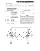
[0027] It will be noted that among the wealth of literature relating to the injection of a cryogenic liquid into a cryogenic chilling device, document EP 1 887 296 is found, which relates to the production of cryogenic mixtures for supplying product chilling devices. This document considers that it is not satisfactory to inject different fluids via separate routes, it recommends producing a mixture upstream of the chilling chamber and injecting this pre-made mixture, it then mixes cryogens (gaseous and/or liquid and/or solid cryogens) in a very conventional manner via the use of an upstream mixing chamber, etc.
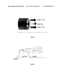
[0028] It will be shown below, especially via comparative examples but also via extremely efficient methods of producing mixtures at the connection point on a device of blender type, that the analysis that this document made is erroneous in the case of blenders with low injection: the separate injections of liquid nitrogen and liquid CO2 on the one hand, and on the other hand the low injection of mixtures of liquid nitrogen and liquid CO2 by producing the mixture at the injection point(s) on the blender give remarkable results, and effectively enable a better utilization of the gases through refrigeration exchanges between the CO2 and the nitrogen.
[0029] According to one of the implementations of the invention, there is additionally, in the top part of the chamber, a system of forced convection that makes it possible to recycle and use the refrigerating power of the cold gases resulting from the low injection of the cryogenic liquids.
[0030] This system of forced convection may be formed by using, for example, fans or else by using a turbine, for example, by way of illustration, fans of 0.38 kW type equipped with 5 blades inclined at 45°.
[0031] According to one of the implementation methods of the invention, the two cryogenic liquids, nitrogen and CO2, are injected at at least one injection point of the device, by producing the mixture at the injection point, the injector used making it possible to carry out an exchange of refrigeration between the two liquids at the point of injection.
[0032] According to one of the forms of such an implementation where the mixing is carried out at the injection point, the injector used is a concentric, twin-tube injector, the liquid CO2 preferably passing through the outer tube (the "coldest" temperature passing through the inside, the "highest" temperature passing through the outside, in contact with ambient temperature).
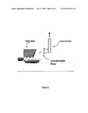
[0033] According to another of the forms of such an implementation where the mixing is carried out at the injection point, the injector used is a concentric, three-tube injector, preferably using the fluids in the following manner: [0034] liquid nitrogen passes through the inner tube; [0035] liquid CO2 passes into the annular space between the first tube and the second tube which is concentric thereto; [0036] liquid nitrogen passes into the annular space between the third, outermost tube and the second tube which is concentric thereto.
[0037] As will be better illustrated below, the experiments carried out by the applicant clearly demonstrate the positive contribution of an injection of two cryogenic liquids instead of one, to several parameters and performances governing such a chilling process.
[0038] Without being in any way limited by the explanations that the applicant puts forward below, it may be considered that the following phenomena take place, very advantageously.
[0039] Two cryogenic liquids are injected into the device, and exchanges of refrigeration between the CO2 and the nitrogen take place, exchanges which are extremely valuable as will be seen.
[0040] The sub-cooling of the snow formed is especially witnessed (it is known that by being at atmospheric pressure the liquid CO2 injected changes to the form of snow and gas), which sub-cooling increases the capacity for transferring refrigeration to the product.
[0041] Furthermore, by considering such situations of low injections in mixers, blenders, etc., witnessed here in all likelihood is the fact that the liquid nitrogen by releasing its kcal into the product, generates gas having a very low temperature in the top of the equipment, and that then the gaseous CO2, rising toward the top of the equipment, solidifies when in contact with the very cold nitrogen present in this gas overhead, which snow may again return to be in contact with the product and transfer its refrigeration to this product (in a way as in a "high injection" type process).
[0042] Moreover, it is understood that then the presence of a forced convection added to the top part of such a blender (for example, via the presence of a fan) may also increase these transfers.
[0043] The invention could furthermore adopt one or more of the following technical characteristics: [0044] the two fluids are injected separately at at least two injection points on the device, and the following three steps for controlling the process are implemented: [0045] i) the two fluids are injected continuously until a setpoint temperature is obtained in the mass of product treated; [0046] j) the injection is stopped for a given stop time (for example a few tens of seconds, for example 30 seconds); [0047] k) the temperature in the mass treated is measured: if the measured temperature is substantially equal to the desired setpoint temperature the blender is changed to shutdown mode, whereas if the measured temperature is greater than the setpoint temperature, the injection is restarted until the setpoint temperature is obtained.
[0048] The expression "shutdown mode" is understood to mean the cessation of blending (and of the injection), the operator can then empty the blender when he considers it appropriate.
[0049] This embodiment is very particularly advantageous for treating batches of materials that are very different (quantity, quality, especially in terms of fat content, etc.) and especially for adapting to the fact that the present invention enables, as will be seen further on, significant reductions in treatment times and therefore a considerably improved productivity, the fact of thus reducing the cycle times having to be carried out without at any moment taking the risk of generating different temperatures according to the volume of product treated. [0050] According to one implementation method of the invention, in order to avoid carrying carbon dioxide snow into the extraction system of the chilling device, it is necessary to promote the absorption of the snow generated in the top part of the chamber by the product, it is then proposed to size the extraction system so as not to promote gas velocities that are capable of conveying snow. Although the desired gas velocities will be different depending on the configuration of the chilling device, the use of extractions referred to as "overflow extractions" will be preferred according to the invention.
[0051] It is recalled that those skilled in the art of chilling or freezing equipment know the principle of these extractions referred to as "overflow extractions" (as illustrated highly schematically in FIG. 7 below), where either a space is left between the equipment and the extraction line, or the extraction line itself is cut at one location.
[0052] The advantages of such a configuration within the context of the present invention are in particular the following: [0053] the "break" enables the discharging of the condensates resulting from the discharging of such cold gases, while limiting the risk of these condensates returning into the equipment; [0054] the "break" makes it possible to limit the discharge velocities and especially to avoid discharge overvelocities and therefore the velocities that would make it possible to discharge not only gas but also snow which forms in the top of the blender (according to the refrigeration exchange mechanism described above as obtained owing to the present invention). [0055] According to one preferred method of implementation of the invention, use is made, on the liquid nitrogen reservoir supplying the device, of a pressure regulation of the liquid phase (regulation of the bottom of the tank), in order to promote conditions where the amount of liquid nitrogen reaching the device is regulated, irrespective of the fill level of the nitrogen reservoir, therefore the height of liquid ("liquid column").
[0056] Reference could be made, for embodiment examples of this regulation of the bottom of the tank, to document WO 2004/005791 A2, for example by acting on the pressure of the gas at the top of the reservoir, for example by vaporizing liquid withdrawn from the bottom of the reservoir in order to form gas sent to the top of said reservoir.
[0057] Other features and advantages of the present invention will thus become more clearly apparent from the following description, given by way of illustration but implying no limitation, in conjunction with the appended drawings in which:
[0058] FIG. 1 is a schematic representation of a conventional mixer from the prior art (for example a meat mixer) having two troughs, employing, on each side of the mixer, a series of liquid nitrogen injection nozzles in the bottom part of the mixer;
[0059] FIG. 2 illustrates one method of implementation of the invention in a blender having one trough, using two separate injections of the two fluids, carried out on the same side of the trough;
[0060] FIG. 3 provides a partial view of the top part (cover) of a mixing chamber in accordance with one of the implementations of the invention, the top part being provided with a forced convection system formed by two fans having five blades inclined at 45°;
[0061] FIG. 4 provides a summary table of tests of implementation of the invention and comparative tests;
[0062] FIG. 5 provides an example of a twin-tube injector that makes it possible to carry out the mixing at the injection point;
[0063] FIG. 6 provides an example of a three-tube injector that makes it possible to carry out the mixing at the injection point; and
[0064] FIG. 7 provides a very partial diagram illustrating an overflow extraction structure, in connection with the top of a blender.
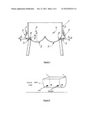
[0065] FIG. 1 shows the lower part of a conventional mixer from the prior art (for example a meat mixer), having two troughs 2 and 3, for which a series of cryogenic fluid, for example liquid nitrogen, injection nozzles are employed on each side of the device.
[0066] Shown symbolically in the figure by the reference 5 are the cryogenic liquid injection nozzles connected to the wall of the mixer, the nozzles themselves being supplied via hoses 6, by a delivery and supply rail 7, advantageously positioned, as is the case shown in this FIG. 1, above the injection nozzles.
[0067] In order not to clutter up the figure unnecessarily, the axes of the rotor shafts of the mixer are represented by simple crosses with the reference 4, one axis per trough of the mixer as shown in FIG. 1.
[0068] As may be understood on examining this FIG. 1, the position of the injection nozzles along the wall of each trough (the angle β), and also the angle of inclination of each injection nozzle with respect to the horizontal (the angle α), have in this case advantageous values for the purpose, on the one hand, of preventing the path of the cryogenic liquid jet from crossing the shafts and rotors of the mixer (avoiding any risk of creating cold spots), while involving a maximum portion of the mass of product to be chilled, contained in the mixer, but also, on the other hand, because of the inclination of the injection nozzle with respect to the horizontal, when subsequently cleaning the mixer with water, of preventing this water from being able to get back into the cryogenic liquid supply line.
[0069] Thus, it is considered that an angle β with respect to the vertical of about 45° gives good results and that an angle α with respect to the horizontal of at least 10° is a setting that it is advantageous to adopt.
[0070] As indicated above, FIG. 3 provides a partial view of the top part of a mixing chamber (cover), the top part of which is here provided with a forced convection system formed by two fans having five blades inclined at 45°. The method represented here is of course only one exemplary embodiment, many other configurations (numbers of fans, numbers of blades per fan, inclination, etc.) may be envisaged without departing from the scope of the present invention.
[0071] The convection system represented in FIG. 3 is that which was used for the practical and comparative examples (with and without high convection) related below.
[0072] FIG. 5 provides an example of a twin-tube injector that makes it possible to carry out the mixing at the injection point, and therefore to achieve an exchange of refrigeration between the two gases at the same point of injection.
[0073] As is preferred according to the invention, the liquid CO2 passes through the outer tube, which promotes the chilling of the CO2 by the nitrogen, limits heat gains and makes it possible easily to generate Venturi effects on the nitrogen.
[0074] As will be clearly apparent to a person skilled in the art, such an injector will be connected to the device in question, for example a blender with low injection, preferably by quick-connection means, especially for cleanability reasons well known to a person skilled in the art.
[0075] FIG. 6 itself illustrates an example of a three-tube injector that makes it possible to carry out the mixing at the injection point. The method illustrated here uses the fluids in the following manner: [0076] liquid nitrogen passes through the inner tube; [0077] liquid CO2 passes into the annular space between the first tube and the second tube which is concentric thereto; [0078] liquid nitrogen passes into the annular space between the third, outermost tube and the second tube which is concentric thereto.
[0079] Here too it will have been understood that this arrangement promotes contact between the two fluids that aims to cool the liquid CO2.
[0080] As already mentioned above, the twin-tube or three-tube injectors in accordance with the invention, making it possible to carry out the mixing at the injection point on the blender, such as those illustrated within the context of FIGS. 5 and 6, may be supplied and connected to the device in question by very simple injector-supply and quick-connection means, but it could also be envisaged to use more complex injector feed valves, such that enable the automated control of the distribution of the fluids between the various channels of the injector (for example a valve driven by a pneumatic actuator).
[0081] Explained in detail in what follows are the conditions of practical implementation examples of the invention and comparative examples, in the case of a blender for chilling masses of meats: [0082] use of a Hobart brand blender, having a single trough (as shown schematically in FIG. 2, and when convection is present it is in accordance with the appended FIG. 3); [0083] low injection system: use of two injectors on the same side of the trough, and two solenoid valves that are driven at the same time (it will have been clearly understood that other configurations of injections, number, on each side, on the same side, etc. can be envisaged and will be chosen as a function of the operating conditions, and especially of the type of blender, of the size of the blender, etc.).
[0084] According to the invention, use may be made of very simple, commercially available injectors such as simple orifices, or else of more elaborate injectors such as those that the applicant has developed as described in documents EP 744 578 and EP 2 041 026. [0085] cryogenic fluid sources used: [0086] use of a reservoir of liquid CO2 stored at 15 bar and -20° C., which reservoir is placed on a balance in order to evaluate the consumption; [0087] use of a reserve of liquid nitrogen at a pressure of 3.6 bar, which reservoir is here too placed on a balance in order to evaluate the consumption; [0088] the product treated was a boneless manufacturing bulk pack of fresh bovine meat containing 20% fat that has undergone a first coarse grinding (freezing point -1° C., water content 62%, specific heat above the freezing point 0.85 kcal/kg, specific heat below the freezing point 0.36 kcal/kg, latent heat 55 kcal/kg); [0089] the initial temperature of the pre-ground meat is within the range extending from 3.5 to 4° C., the reference temperature after grinding is substantially-1° C. [0090] the average time for one mixing cycle is customarily, on this industrial site, 12 minutes, with low CO2 injection. [0091] Protocol followed: [0092] Measurement of the temperature of the fresh boneless manufacturing bulk pack incorporated into the blender. [0093] Injection of the cryogenic liquids continuously, with or without the presence of forced convection (63 Hertz), being based on two coupled and monitored factors: [0094] a temperature of the meat in the grinder of -0.6° C. to -1° C.; [0095] a motor intensity of 6 amperes. [0096] At the same time: [0097] The intensity of the blender is revealed owing to a hook-on ammeter. [0098] The temperatures inside the blender, on the outside of the blender (level with the opening/closure of the cover) and the temperature of the extraction gases are recorded. [0099] Measurement of the temperature of the boneless manufacturing bulk pack after grinding. [0100] Inspection of the visual appearance and the texture of the ground manufacturing bulk pack and also of the steak formed downstream by a production manager, inspections complemented by a bacteriological analysis of the product formed. [0101] The tests are carried out on batches of 150 kg of meat (depending on the test in question, the test is repeated 3 to 4 times to ensure a good reproducibility and representativeness of the results observed). [0102] In all cases, the tests use injectors of simple type (simple lines connected to the mixer). [0103] Tests No. 1--comparative: injection of liquid nitrogen alone, without use of additional convection. [0104] Tests No. 2--according to the invention: tests without use of convection, injection of the two cryogenic liquids separately in accordance with FIG. 2 (two injectors on the same side of the mixer). [0105] Tests No. 3: same tests as No. 2 but here with additional use of high convection.
[0106] In other words, these tests are characterized by a constant of the intensity parameters at the end of treatment (6 A), of the freezing hold (the intensity at the end of treatment still being the same), of the boneless manufacturing bulk pack used and pre-ground, of the weight of batch treated, of the setpoint temperature after desired grinding (substantially -1° C.).
[0107] The results of the tests are assembled in the table presented in FIG. 4 below, which results make it possible to draw the following conclusions: [0108] by the implementation of the invention, a reduction in treatment time is clearly observed, which reduction is even higher when additional high convection is used; [0109] a decrease in the consumption of fluid used is also clearly observed. This decrease in consumption must be connected to the sub-cooling of the CO2 carried out owing to the invention, but also to the limitation of the calefaction phenomenon, thus improving the heat transfer; [0110] the presence of forced convection makes it possible to further improve each of these performances (treatment time and consumption); [0111] in other words, the treatment lasts for less time, the motors are therefore used for less time, which enables the input of fewer calories originating from outside and a lower mechanical energy of the motors transferred to the system; [0112] the amount of refrigeration transferred to the mass with respect to the customary treatment conditions of the site is the same, the transfer has therefore been improved, whether this is with the presence of convection or without the presence of high forced convection. More specifically, the optimization of the process must be connected to a synergy of cumulated effects.
[0113] The use of two fluids makes it possible to operate with a sub-cooled CO2, injected within the mass of material, while creating a cold gas overhead, capable of resolidifying the gaseous CO2 escaping toward the top of the chamber.
[0114] Moreover, it is understood, when a high forced convection is used, that this only reinforces these effects.
[0115] With regard to the role of this forced convection, these results unambiguously demonstrate the fact that this forced convection introduced into the top part of the chamber has an unmistakable and positive effect on the overall transfer of refrigeration carried out on the mass treated.
[0116] This might appear paradoxical considering the compact mass treated, or else considering the time available during the treatment, which time might appear to be too short.
[0117] It is possible to attempt to provide the following explanation: by way of comparison, in a conventional cryogenic tunnel, a fan of 0.20 kW/m2 is installed in order to achieve a convection of 80 W/m/K. According to the present invention, and to its credit, it is typically possible to install 7.5 kW over a single m2, in order to have a convection that can be estimated at around 200 W/m2/K, which is considerable.
[0118] It is possible to consider that the conditions of the invention then partly approach impingement type convections.
User Contributions:
Comment about this patent or add new information about this topic:
Images included with this patent application:
 | 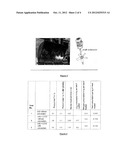 |
 |  |
 |
| New patent applications in this class: | |
| Date | Title |
|---|---|
| 2019-05-16 | Cryogenic cooling systems and methods of controlling product temperatures during delivery |
| 2016-05-26 | Control method for a hybrid refrigeration system |
| 2016-05-26 | Eutectic device for a transport refrigeration system and methods for cooling and installing the eutectic device |
| 2016-04-28 | Cooling apparatus and method |
| 2015-12-24 | Cryogenic poultry chilling system and method |
| New patent applications from these inventors: | |
| Date | Title |
|---|---|
| 2016-02-25 | Method and facility for supplying at least one machining station with subcooled cryogenic liquid |
| 2013-04-11 | Method of precooking the surface of food products with a view to marking them or hardening them |
| 2011-09-15 | Method for shaping a food product by cryoextrusion employing predictive temperature regulation |
| Top Inventors for class "Refrigeration" | |
| Rank | Inventor's name |
|---|---|
| 1 | Michael F. Taras |
| 2 | Alexander Lifson |
| 3 | Koji Yamashita |
| 4 | Hiroyuki Morimoto |
| 5 | Patrick J. Boarman |