Patent application title: ARCHERY BOW STABILIZER
Inventors:
Kyle B. Stokes (Annville, PA, US)
IPC8 Class: AF41B520FI
USPC Class:
124 89
Class name: For archery projector bow handle or attachment thereto for stabilization thereof
Publication date: 2012-09-27
Patent application number: 20120240913
Abstract:
A stabilizer for an archery bow including an elongated member having a
first portion adapted to flex and oscillate, thereby absorbing bow shock
and/or vibration, and a second portion stiffened to maintain at least
part of the elongated member in a relatively stationary position, thereby
minimizing its movement as the bow is shot. The elongated member can be
hollow and tubular, and can be constructed from laminated carbon prepreg,
or other lightweight carbon, composite and/or polymeric material. The
first portion can include a fabric or other flexible material. The second
portion can include a more dense, heavier or other, different material so
that the second portion is more rigid, dense, heavy and/or stiff than the
first portion. The stabilizer can include an optional weight module
having multiple replaceable and selectively positionable weight elements.Claims:
1. An archery stabilizer adapted to attach to an archery bow, the archery
stabilizer comprising: an attachment element including a fastening
element configured to attach to an archery bow; an elongated member in
the form of a hollow tube, the hollow tube comprising carbon material,
the elongated member including a proximal end joined with the attachment
element so that the proximal end is adjacent the archery bow to which the
stabilizer is joined, the elongated member including a distal end located
a preselected distance from the proximal end, the elongated member
including a first portion and a second portion, the first portion being
of a first stiffness, the second portion being of a second stiffness less
than the first stiffness, the first stiffness of the first portion
enabling the first portion to flex and oscillate when the archery bow is
shot, thereby absorbing at least one of bow shock and vibration, the
second lesser stiffness enabling the second portion to maintain the
distal end in a relatively stationary position, thereby minimizing
movement of the distal end when the bow is shot; and at least one of an
end cap and a weight module joined with the distal end of the elongated
member, away from the archery bow.
2. The stabilizer of claim 1, wherein the first portion is of a first density, wherein the second portion of a second density, wherein the first density less than the second density so that the second portion weighs more per inch than the first portion weighs per inch and so that the second portion is heavier than the first portion.
3. The stabilizer of claim 1 wherein the attachment element includes a stud and an attachment body, the attachment body including at least one of a recess and a projection, the recess configured to receive the proximal end of the elongated member, the projection sized for insertion into a bore defined by the elongated member.
4. The stabilizer of claim 3 wherein the attachment body includes both a recess and a projection, with the projection located in the bore, and the proximal end located in the recess.
5. The stabilizer of claim 1 wherein the hollow tube is constructed from a pre-impregnated carbon composite mat.
6. The stabilizer of claim 1 comprising a stiffness layer joined with the second portion to enhance the stiffness of the hollow tube in the second portion.
7. The stabilizer of claim 1 wherein the weight module is joined with the distal end of the elongated member, the weight module including a recess that receives the distal end of the elongated member.
8. An archery stabilizer adapted to attach to an archery bow, the archery stabilizer comprising: an attachment element configured to join with an archery bow; a dual spine elongated member comprising carbon, the dual spine elongated member including at least two portions having different stiffness, the dual spine elongated member joined with the attachment element; and at least one of an end cap and a weight module joined with the elongated member, away from the archery bow.
9. The stabilizer of claim 8 wherein the dual spine elongated member includes a first portion having a first stiffness enabling the first portion to flex and oscillate when the archery bow is shot, thereby absorbing at least one of bow shock and vibration, and wherein the dual spine elongated member includes a second portion having a second stiffness lesser than the first stiffness enabling the second portion to maintain an end of the dual spine elongated member in a relatively stationary position, thereby minimizing movement of the end when the bow is shot.
10. The stabilizer of claim 8, wherein the at least two portions include a first portion and a second portion, wherein the first portion is of a first density, wherein the second portion of a second density, wherein the first density less than the second density so that the second portion weighs more per inch than the first portion weighs per inch and so that the second portion is generally heavier than the first portion.
11. The stabilizer of claim 10 wherein the dual spine elongated member includes a proximal end joined with the attachment element so that the proximal end is adjacent the archery bow to which the stabilizer is joined, wherein the elongated member includes a distal end located a preselected distance from the proximal end.
12. The stabilizer of claim 10 wherein the attachment element includes a threaded stud configured to join with a threaded hole defined by an archery bow,
13. The stabilizer of claim 10 wherein the dual spine elongated member is in the form of a hollow cylindrical tube constructed from a pre-impregnated carbon composite mat.
14. The stabilizer of claim 10 wherein the dual spin elongated member comprises a stiffness layer, the stiffness layer including at least one of laminated fabric, metal foil, metal screen, metal tubing, and a protective coating.
15. An archery stabilizer adapted to attach to an archery bow, the archery stabilizer comprising: an attachment element configured to join with an archery bow; an elongated member joined with the attachment element, the elongated member including a proximal end joined with the attachment element so that the proximal end is adjacent the archery bow to which the stabilizer is joined, the elongated member including a distal end located a preselected distance from the proximal end; and a weight module joined with distal end of the elongated member, away from the archery bow, the weight module including a longitudinal axis aligned generally with the elongated member, the weight module defining a plurality of holes opposite the elongate member, the weight module including at least one weight element selectively secured within at least one of said plurality of holes to impart a preselected weight distribution to the stabilizer.
16. The stabilizer of claim 15 wherein the plurality of holes are located at equal distances from and are radially spaced around the longitudinal axis.
17. The stabilizer of claim 15 wherein the plurality of holes are threaded, wherein the at least one weight element includes a corresponding thread so that the at least one weight element is threadably coupled to the weight module.
18. The stabilizer of claim 16 wherein the weight module includes a neck, wherein the neck defines a recess, wherein the elongated member is located in the recess.
19. The stabilizer of claim 15 wherein the elongated member is a dual spine hollow tube comprising carbon.
20. The stabilizer of claim 15 wherein the at least one weight element includes a drive feature, and wherein the weight module defines a hole coincident with the longitudinal axis.
Description:
BACKGROUND OF THE INVENTION
[0001] The present invention relates generally to archery, and more particularly, to a stabilizer for attachment to an archery bow for lateral stabilization, for torque reduction, and for absorbing and dampening bow vibration.
[0002] There are a variety of stabilizers designed to attach to an archery bow and reduce the tendency of the bow to be laterally and/or rotationally displaced as, and after, an arrow is shot from the bow. In addition, a number of stabilizers attempt to cushion bow shock and vibration, which are common effects when an arrow is shot from the bow.
[0003] Most conventional stabilizers are of a simple construction, including a long rod having first and second ends. The first end includes a threaded portion designed to be fastened to the bow. The second end usually includes a weighted body. While providing lateral stability to the bow, most stabilizers can actually amplify vibration and/or oscillation, which can be undesirable. To mitigate this, the weight or portions of the rod can include elastomeric materials that absorb the vibration. While this is satisfactory in some cases, it usually does not result in exceptional stabilization and vibration or shock reduction.
SUMMARY OF THE INVENTION
[0004] A stabilizer for an archery bow is provided including an elongated member having a first portion which is adapted to flex and oscillate, thereby absorbing bow shock and/or vibration, and a second portion which is stiffened to maintain at least part of the elongated member in a relatively stationary position, thereby minimizing its movement as the bow is shot.
[0005] In one embodiment, the elongated member includes a first end, which mounts adjacent an archery bow when the stabilizer is attached to the bow, and a second end, which is distal from the bow. The second portion can be stiffened to maintain a distal end of the elongated member in a relatively stationary position, thereby minimizing its movement as the bow is shot.
[0006] In another embodiment, the elongated member is a tubular member of a dual or multi spine carbon construction. The first portion is configured to be proximal the bow and the second portion is configured to be distal from the bow, with the first portion located between the second portion and the bow. Optionally, the first and second portions are reversed in spatial relationship to the bow and each other.
[0007] In yet another embodiment, the first portion can include a hollow tubular core constructed from laminated carbon prepreg, or other lightweight carbon or composite material. This tubular core can extend into and through the second portion. The tubular core in the first portion can be reinforced with a fabric or other flexible material. In the second portion, the tubular core can be reinforced with a more dense, heavier or other, different material so that the second portion is more rigid and/or stiff than the first portion. The different material can be of a different thickness or weight.
[0008] In still another embodiment, the second portion can be rigid or stiff, and configured to maintain the distal end of the stabilizer in a relatively stationary position to minimize movement and reduce lateral instability and/or torque when the archery bow is drawn, held and/or shot. The first portion adjacent the bow can be configured to be less rigid or stiff to enable the tube to flex and/or oscillate, and thereby absorb bow shock and vibration.
[0009] In even another embodiment, the first portion can be fused, fastened, molded or otherwise joined with the second portion. The first portion can be constructed from a first material that is generally more dense or stiff, and the second portion can be constructed from a different material that is less dense or less rigid than the first material.
[0010] In still yet another embodiment, where the first portion is less stiff than the second portion, the first portion can extend for about two-thirds the length of the elongated member, and the second portion can extend approximately one-third the length of the elongated member. Optionally, the relative length of the portions can vary. For example, the first portion can extend about three-quarters the length of the elongated member and the second portion can extend about a quarter of the length of the elongated member. As another example, the first and second portions can extend each about half the length of the elongated member. Other lengths of the respective portions are contemplated.
[0011] In a further embodiment, the stabilizer can include a weight module joined with the distal end of the elongated member, opposite the archery bow. The weight module can define multiple apertures into which weighted elements can be selectively positioned. Optionally, the apertures can be radially placed equal distances from one another about a central axis of the weight module.
[0012] In yet a further embodiment, each of the apertures of the weight module can be threaded. Each of the weights can be correspondingly threaded. The weight elements can include a grippable and/or drive feature so that they can be threaded into the respective apertures.
[0013] In still another embodiment, the weight elements can be selectively positioned in preselected ones of the apertures to provide desired performance characteristics and balance or stabilization features.
[0014] The stabilizer described herein provides a simple and efficient construction that stabilizes an archery bow and absorbs vibration and shock. For example, the stiffer or more rigid portion of the stabilizer maintains the distal end of the stabilizer in a stationary position to minimize lateral displacement and/or rotation of the archery bow when being held and/or shot. The proximal, less stiff or less rigid portion of the stabilizer flexes and/or oscillates, thereby absorbing bow shock and vibration when the bow is shot. Where included, the weight module provides and quick and easily adjusted construction that can redistribute the weight of the stabilizer to the archer's preference, which can greatly enhance shooting accuracy and the archer's confidence.
[0015] These and other features and advantages of the present invention will become apparent from the following description, accompanying drawings and appended claims.
[0016] Before the embodiments of the invention are explained in detail, it is to be understood that the invention is not limited to the details of operation or to the details of construction and the arrangement of the components set forth in the following description or illustrated in the drawings. The invention may be implemented in various other embodiments and of being practiced or being carried out in alternative ways not expressly disclosed herein. Also, it is to be understood that the phraseology and terminology used herein are for the purpose of description and should not be regarded as limiting. The use of "including" and "comprising" and variations thereof is meant to encompass the items listed thereafter and equivalents thereof as well as additional items and equivalents thereof. Further, enumeration may be used in the description of various embodiments. Unless otherwise expressly stated, the use of enumeration should not be construed as limiting the invention to any specific order or number of components. Nor should the use of enumeration be construed as excluding from the scope of the invention any additional steps or components that might be combined with or into the enumerated steps or components.
BRIEF DESCRIPTION OF THE DRAWINGS
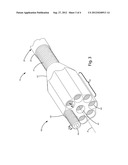
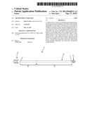
[0017] FIG. 1 is a perspective view of a current embodiment of the stabilizer.
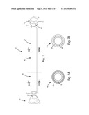
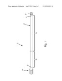
[0018] FIG. 2 is a side view of the stabilizer.
[0019] FIG. 2A is a section view of the stabilizer taken along lines 2A-2A of FIG. 2.
[0020] FIG. 2B is a section view of the stabilizer taken along lines 2B-2B of FIG. 2.
[0021] FIG. 3 is a close-up perspective of an optional weight module of the stabilizer.
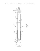
[0022] FIG. 4 is a side section view of an alternative embodiment of the stabilizer.
DETAILED DESCRIPTION OF THE CURRENT EMBODIMENT
[0023] A stabilizer of the current embodiment is illustrated in FIGS. 1-3 and generally designated 10. The stabilizer 10 can include an elongated member 20 to which an attachment member 50 is joined to secure the elongated member 20 to the bow at a proximal end 21 of the elongated member 20. Opposite the proximal end 21, a weight module 60 can be joined to the distal end 22 of the elongated member 20.
[0024] The elongated member 20 can include a first portion 30 and a second portion 40. The first portion 30 can be adjacent the proximal end 21, and generally near or adjacent an archery bow when the stabilizer is installed thereon. The second portion 40 can be distanced from the bow, with the attachment member 50 and first portion 30 between it and the bow. Alternatively, the first and second portions, with their respective stiffness and/or rigidity as described herein, can be reversed so the second portion is closer to the bow.
[0025] As shown in the embodiment of the figures, the first portion 30 can form approximately half, two-thirds or three-quarters of the length of the elongated member 20. The corresponding second portion 40 can form one-half, one-third, or one-quarter, respectively, of the total length of the elongated member 20. Of course, depending on the specific performance characteristics of the stabilizer and the archer's preference, the first and second portions can be of different relative proportions. For example, the first portion 30 optionally can be at least about 5%, 10%, 15%, 20%, 25%, 30%, 35%, 40%, 45%, 50%, 55%, 60%, 65%, 70%, 75%, 80%, 85%, 90%, or 95% the total length of the elongated member 20, with the second portion 40 forming the balance of the total length of the elongated member, or vice versa.
[0026] Optionally can be multiple first portions and multiple second portions having the respective stiffness and/or rigidity characteristics mentioned herein, mixed and matched with one another throughout the length of the elongated member 20. For example, there can be a first portion, a second portion and a third portion, with the second portion being located between and more rigid, stiff or dense than the first and third portions. The second portion can be at least about can be at least about 5%, 10%, 15%, 20%, 25%, 30%, 35%, 40%, 45%, 50%, 55%, 60%, 65%, 70%, 75%, 80%, 85%, 90%, or 95% the total length of the elongated member, with the first portion and third portion collectively forming the balance of the total length of the elongated member. Alternatively, the second portion can be less rigid, stiff or dense than the first and third portions.
[0027] The elongated member can be of a variety of lengths, so that the proximal end and the distal end are separated by a variety of preselected distances therebetween, depending on the application in which the stabilizer is used. For example, the elongated member can be of a length in a range of about 3 inches to about 12 inches for applications where the stabilizer is used in bow hunting applications. The elongated member can also be of a length in a 6 inches to about 24 inches in applications where the stabilizer is used in tournament or target shooting applications. Of course, the ranges of lengths can vary from those noted above depending on the preferences and shooting preferences of the archer.
[0028] Returning to FIGS. 1-3, the attachment member 50 can include an attachment body 52 to which a fastener, such as a stud 54, or some other fastener or fastener hole or other device capable of attaching the stabilizer to the bow, can be integrally defined, formed or attached. The attachment body 52 can define an aperture 56 into which the proximal end 21 of the elongated member 20 can be inserted. Alternatively, the body 52 can be of a dimension so that it can be inserted within a portion of the proximal end 21 (not shown). The proximal end 21 can be joined with a body 52 of the attachment element 50 by cementing, epoxying, gluing or otherwise fastening the proximal end to the body 52.
[0029] The elongated member 20 can be constructed so that it effectively has a "spine," which describes the overall stiffness of the elongated member. More particularly, the elongated member 20 can have a dual or multiple spines, where the stiffness of different portions of the elongated member differs along the length of the elongated member. For example, the first portion 30 can be less stiff, less rigid and/or can be of a weaker spine than the second portion 40, which can be more stiff, more rigid and/or can be of a stiffer spine than the first portion 30, or vice versa. The methodology for testing and evaluating the spine can be similar to that of the industry standard measurements used for evaluating arrow shaft stiffness or a modification thereof.
[0030] The different spines of the different portions of the elongated member 20 can be produced in a variety of manners. For example, referring to the cross sections in FIGS. 2A-2B, the elongated member can include a central core 38 that extends the length of the elongated member from the distal end 22 to the proximal end 21. The core 38 can be hollow and tubular. Of course, if desired, it could alternatively be solid. The core can be constructed from a laminated carbon prepreg or other lightweight carbon, and/or composite material. Of course, the core can be formed from fiberglass, a resin impregnated fabric, metal tubing (e.g., aluminum) or an aluminum alloy or a titanium, or from a laminated combination, or hybrid, of fiberglass and a composite material. Optionally, the core can be of a continuous constant inside and outside diameter. Further optionally, the core 38 can be tapered from one end to the other, thereby having a larger diameter at one end than the other. The taper can be continuous or stepped or can otherwise vary.
[0031] As shown in FIGS. 2A-2B, the stiffness or spine of the respective portions optionally can be varied by joining a first material 36 to the core 38 in the first portion 30, and a second material 46 to the core 38 in the second portion 40. The second material 46 can differ from the first material 36 in that it can be generally more dense or more stiff or otherwise provide more rigidity to the core 38 than the first material 36. As an example, the core 38 can be wrapped with a relatively heavy and/or dense fabric or other flexible material in the second portion 40. A less dense fabric or flexible material can be wrapped around the core 38 in the first portion 30 so that the first portion is less stiff or less rigid than the second portion 40. Alternatively, the respective first and second materials can be disposed within the core 38 (not shown) to affect rigidity, stiffness and the like.
[0032] Optionally, the second portion 40 can include a stiffness layer, constructed from metal screen, foil or thin metal tube in addition to the material 46, or in place of that material 46, to increase the rigidity and/or stiffness of the second portion 40 of the elongated member 20 over that of the first portion 30. Further optionally, the first material 36 used for the first portion 30 of the elongated member 20 can have a first density, or weight per standard length measurement, for example, grams per inch or per centimeter, provided with the material at a standard thickness. The second material 46 used for the second portion 40 can have a second density for a given width of the material at a standard thickness thereof. The first density can be less than the second density. Even further optionally, the second material 46 can simply be combined with a stiffness layer, such as a metal screen, foil or thin metal tubing to provide the perceived different densities and/or rigidities of the elongated member in the different first and second portions.
[0033] Optionally, the first portion 30 can be less dense or of a lesser weight per unit of length than the than the second portion 40, or vice versa. For example, the first portion 30 can about 10-30 grams per inch (gpi), whereas the second portion 40 can be about 30-60 gpi. Of course, these weights can be reversed, or can vary depending on the application. As a few examples, the first portion can be about 15 gpi and the second portion about 25 gpi, the first portion can be about 20 gpi and the second portion about 35 gpi, the first portion can be about 25 gpi and the second portion about 40 gpi, the first portion can be about 30 gpi and the second portion about 45 gpi, or the first portion can be about 30 gpi and the second portion about 50 gpi.
[0034] Although the different materials 36 and 46 are illustrated as being located on the exterior of the tubular core 38, those materials can alternatively be positioned on the interior of the core, that is, within the internal diameter of the core 38. Further, the materials 36 and 46 can be included on both the interior and exterior of the core in varying combinations. Additional materials to vary the spine or stiffness of the elongated member in the different portions can also be added on the interior and/or the exterior of the core 38.
[0035] Suitable materials and configurations for varying the density of different portions of the elongate member are disclosed in connection with arrow shafts in U.S. Pat. No. 7,608,022 to Eastman II et al, which is hereby incorporated by reference in its entirety.
[0036] While the elongated member 20 is shown in the form of a tubular member of a circular cross section, it can alternatively be non-tubular, that is, solid or at least partially solid, channel shaped, or of a variety of geometric cross sections, for example, elliptical, triangular, square, polygonal, rectangular and the like. Optionally, the elongated member can be of a substantially constant inside and outside diameter from the proximal end to the distal end, generally throughout its entire length. Of course, depending on the construction, the diameters can vary to provide certain performance characteristics if desired.
[0037] The distribution of different stiffness, densities, weights and/or the dual spine of the elongated member is believed to allow the first or weaker/less stiff portion of the elongated member to flex or oscillate, thereby absorbing bow shock and vibration, while still enabling the stiffer second portion of the elongated member to maintain the distal end of the elongated member and anything associated with it in a relatively stationary position thereby minimizing movement and lateral displacement of that end and therefore providing an increased stability to the archery bow when held by an archer. Generally, where implemented, it is believed that the forward or rearward of center stiffness, density, rigidity or weight distribution along the elongated member allows the elongated member, and thus the bow, to recover more quickly from oscillation and vibration from a shot, than a stabilizer with an elongated member of a constant stiffness, density, rigidity or weight distribution throughout it.
[0038] To the distal end 22 of the elongated member 20 a weight can be added. The weight can be a simple elastomeric plug weight (not shown), which is simply inserted into the end of the elongated member. Optionally, the distal end of the elongated member can simply be capped with an end cap, in the form of a lightweight plug that fits in or over the distal end, or a cap that fits over the distal end of the elongated member, to protect the distal end 22. Further optionally, the distal end can remain uncapped if desired.
[0039] In the current embodiment as shown in FIG. 3, however, a weight module 60 is joined with the distal end 22 of the elongated member 20. This weight module 60 can be joined with the elongated member 20 in a variety of manners. As illustrated in FIG. 3, the weight module 60 can include a neck 61 which can be inserted into the internal bore of the elongated member 20. The neck 61 can be joined with glue, epoxy, cement or other fasteners, like the attachment element 50 described above. As shown in FIG. 2, the neck alternatively can define a bore 23 be configured to fit over the distal end 21 of the elongated member 20. The fastening mechanism can be the same as that mentioned above with regard to the proximal end attaching to the attachment element if desired.
[0040] The weight module 60 can define multiple holes 64. These holes can be radially spaced about a central axis A of the module and can be equal distance from one another. Alternatively, the holes can be positioned in a grid-like pattern, or any other configuration as desired. The module optionally can define a centrally located hole 65 that is generally aligned with and coincident with the axis A.
[0041] Each of the respective holes defined by the module 60 can be configured to receive weight elements 66. In the embodiment illustrated, one mechanism for joining the weighted element 66 with the module is to include mated threads on the weight element 66 and within the hole 64. Optionally, the holes can be void of threads for a certain portion adjacent the exterior of the module. Likewise, the weighted element 66 can be void of threads for a preselected distance 68. With this configuration, the holes and weighted elements have a smooth surface and appear to have a clean, finished appearance when installed in the weight module. Of course, if desired, the threads can extend to the outermost portion of the weight module.
[0042] Each of the weight elements 66 can include a drive feature that mates with a common drive tool so that the respective weight elements can be threaded into the respective holes. Although not shown, if desired, the weight elements 66 can include a gnurled section so that the weights can be manually threaded into the respective holes.
[0043] In use, a user can preselect, by trial and error, the weight distribution and number of weight elements to include in the respective holes defined by the weight module. Various combinations of the holes can be filled with respective weight elements. In some of the embodiments, all of the holes of the weight module can be filled, while in others, only selected ones or one of the one or none can be filled, depending again on the archer's preference.
[0044] A first alternative embodiment of the stabilizer is shown in FIG. 4 and generally designated 110. This stabilizer is similar to the construction of the stabilizer of the embodiment described above with a few exceptions. For example, the stabilizer 110 can include an elongated member 120 having a first portion 130 and a second portion 140. The first portion 130 can be constructed from a first material 138, such as a pre-impregnated carbon composite mat, known as prepreg, having a first density or weight per standard linear measure, such as gpi. The second portion 140 can be constructed from a second material 148, such as prepreg, where the second material 148 can be more dense, or there simply can be more second material in the second portion, than the first material in the first portion, or vice versa.
[0045] Optionally, the second portion, whether or not constructed of a more dense, heavier or different material, can also or alternatively include another covering or stiffness layer 144, such as a laminated fabric, a sleeve, metal foil, metal screen, thin metal tubing, and/or protective coating of polymeric or other material. This covering or stiffness layer can provide added stiffness, density, weight and/or a different spine to the second portion, which differs from that of the first portion. For example, the stiffness, density, weight and/or spine of the second portion can be greater than that of the first portion, or vice versa depending on the desired function of the stabilizer. Further optionally, although shown as an external covering or stiffness layer 144, that layer can be located on the inner bore of the second portion or elongated member if desired. Even further optionally, although shown as generally uniform layers, the first and second portions can be constructed as laminated, multilayer components.
[0046] As also shown in FIG. 4, the stabilizer 110 can include an attachment element 150. The attachment element can include a stud 154 configured to secure the stabilizer to a bow. The element 150 also can include a projection or connector 152, which can generally connect the elongated member 120 to the attachment element 150. This connector 152 can be in the form of a projection or boss that can slide or otherwise fit inside an optional internal bore 120B of the elongated member 120. The projection can be friction fit within the elongated member, and/or optionally can be cemented, glued, or otherwise fastened to the elongated member to further secure these components to one another.
[0047] As further shown in FIG. 4, the stabilizer 110 can include a weight module or end cap 160. This weight module can include a projection or connector 162, which can generally connect the elongated member 120 to the weight module 150. This connector 162 can be in the form of a projection or boss that can slide or otherwise fit inside an optional internal bore 120B as well. This projection also can be friction fit within the elongated member, and/or optionally can be cemented, glued, or otherwise fastened to the elongated member to further secure these components to one another.
[0048] The above description is that of current embodiments. Various alterations and changes can be made without departing from the spirit and broader aspects of the invention as defined in the appended claims, which are to be interpreted in accordance with the principles of patent law including the doctrine of equivalents. This disclosure is presented for illustrative purposes and should not be interpreted as an exhaustive description of all embodiments of the invention or to limit the scope of the claims to the specific elements illustrated or described in connection with these embodiments. For example, and without limitation, any individual element(s) of the described invention may be replaced by alternative elements that provide substantially similar functionality or otherwise provide adequate operation. This includes, for example, presently known alternative elements, such as those that might be currently known to one skilled in the art, and alternative elements that may be developed in the future, such as those that one skilled in the art might, upon development, recognize as an alternative. Further, the disclosed embodiments include a plurality of features that are described in concert and that might cooperatively provide a collection of benefits. The present invention is not limited to only those embodiments that include all of these features or that provide all of the stated benefits, except to the extent otherwise expressly set forth in the issued claims. Any reference to claim elements in the singular, for example, using the articles "a," "an," "the" or "said," is not to be construed as limiting the element to the singular. Any reference to claim elements as "at least one of X, Y and Z" is meant to include any one of X, Y or Z individually, and any combination of X, Y and Z, for example, X, Y, Z; X, Y; X, Z; and Y, Z.
User Contributions:
Comment about this patent or add new information about this topic:
Images included with this patent application:
 |  |
 |  |
 |
| Similar patent applications: | |
| Date | Title |
|---|---|
| 2011-03-10 | Archery bow stabilizer |
| 2011-05-26 | Archery bow stabilizer |
| 2012-07-12 | Archery bow stabilizer |
| 2013-03-07 | Archery bow cable guard |
| 2010-06-03 | Archery bow axle |
| New patent applications in this class: | |
| Date | Title |
|---|---|
| 2019-05-16 | Archery bow with ballast stabilizer |
| 2016-05-05 | Apparatus for mounting a sidebar to an archery bow |
| 2016-03-10 | Stabilizer shock mount |
| 2016-03-03 | Positioning system and device for archery bow stabilizers |
| 2015-12-03 | Continuous articulating archery stabilizer |
| New patent applications from these inventors: | |
| Date | Title |
|---|---|
| 2014-07-17 | Archery bow stabilizer |
| 2010-04-29 | Cable guard and guide for archery bows |
| 2010-04-08 | Cable guard and guides for archery bows |
| Top Inventors for class "Mechanical guns and projectors" | |
| Rank | Inventor's name |
|---|---|
| 1 | Mathew A. Mcpherson |
| 2 | Richard L. Bednar |
| 3 | Michael J. Shaffer |
| 4 | Tetsuo Maeda |
| 5 | Jacob A. Hout |