Patent application title: BUMPER FOR A VEHICLE
Inventors:
Per Muskos (Lulea, SE)
IPC8 Class: AB60R1926FI
USPC Class:
293132
Class name: Vehicle fenders buffer or bumper type bumper having impact force absorbing means directly interposed between bumper and vehicle structure
Publication date: 2012-09-06
Patent application number: 20120223536
Abstract:
A bumper with integrated crumple is formed from a central beam (11) and
two outer beams (12,13), the ends of the central beam and adjacent ends
of the outer beams being curved and welded together to form the crash
boxes (14,15).Claims:
1. Bumper for a vehicle, comprising a bumper beam and two crash boxes
with closed profile, characterised in that the bumper beam comprises a
central beam (11) and two outer beams (12, 13), the ends of the central
beam and adjacent ends of the outer beams being curved and welded
together to form the crash boxes (14, 15).
2. Bumper according to claim 1, characterised in that the ends of the crash boxes are welded to a fastening plate (16).
3. Bumper according to claim 1, characterised in that the three beams (11, 12, 13) have a U-profile with its opening toward the vehicle and these profiles are inverted where they form the crash boxes (14, 15).
4. Bumper according to claim 2, characterised in that the three beams (11, 12, 13) have a U-profile with its opening toward the vehicle and these profiles are inverted where they form the crash boxes (14, 15).
Description:
TECHNICAL FIELD OF THE INVENTION
[0001] The invention deals with a bumper for a vehicle, comprising a bumper beam and two crash boxes with closed profile. The bumper beams are oriented transverse to the vehicle, while the crash boxes are oriented along the vehicle and are fastened to the vehicle.
PURPOSE AND BRIEF DESCRIPTION OF THE INVENTION
[0002] One purpose of the invention is to simplify and economise on the manufacture of a bumper of this kind. This is achieved in that the bumper beam comprises a central beam and two outer beams, the ends of the central beam and the adjacent ends of the outer beams being curved and welded together to form the crash boxes.
BRIEF DESCRIPTION OF THE DRAWINGS SHOWING A SAMPLE EMBODIMENT OF THE INVENTION
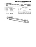
[0003] FIG. 1 is a top view of a bumper.
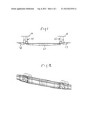
[0004] FIG. 2 is a perspective view of the same bumper.
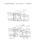
[0005] FIG. 3 shows a magnified view of part of the bumper in FIGS. 1 and 2.
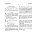
[0006] FIG. 4 is an exploded view of FIG. 3.
DETAILED DESCRIPTION OF THE ILLUSTRATED AND PREFERRED EXAMPLE OF THE INVENTION
[0007] The bumper shown in the figures consists of a central beam 11 and two outer beams 12,13 and the three beams are welded together and form integrated crash boxes 14,15 which have fastening plates 16,17 for attachment to supporting parts of the vehicle, often for attachment to corresponding fastening plates on the side rails of the vehicle. All three beams have a U-profile with the opening toward the vehicle. The ends of the beams facing each other are curved toward the vehicle and form in pairs crash boxes which are thus integrated parts of the beams.
[0008] FIGS. 3 and 4 show a magnified view of the crash box 15 and adjacent parts of the beams 11 and 13. The larger part of the central flange 18 of the central beam consists of a broad middle groove 19. As best seen in FIG. 4, the exploded view, the middle groove deepens toward the curved ends so that the central beam has an inverted U profile 20 there. The outer beam 13 has a corresponding appearance with a middle groove 21 and this beam also has an inverted U profile 22 at the curved ends. The two U-profiles 20 and 22 and their extensions in the form of the end edges 23, 24 of the original U-profiles are placed against each other and welded together. One edge of the inverted U-profile is preferably placed overlapping the other to provide a stronger joint, as shown in FIG. 3.
[0009] The two inverted U-profiles 20,22 thus form crash boxes 15 having a closed cross section and oriented in the lengthways direction of the vehicle, i.e., transverse to the bumper beam 11,12,13 and integrated with it. The fastening plate 17 is welded to the ends of the two inverted U-profiles 20,22.
[0010] Crash box 14 is formed in the same way.
User Contributions:
Comment about this patent or add new information about this topic:
Images included with this patent application:
 |  |
 |  |
| Similar patent applications: | |
| Date | Title |
|---|---|
| 2010-12-23 | Bumper beam for a vehicle |
| 2013-05-23 | Bumper system for a vehicle |
| 2013-08-08 | Laminate bumper for material handling vehicles |
| 2009-06-18 | Bumper beam for vehicles |
| 2009-10-29 | Bumper system for vehicle |
| New patent applications in this class: | |
| Date | Title |
|---|---|
| 2022-05-05 | Vehicle-mounted crash attenuator |
| 2016-07-14 | Bumper assemblies for vehicles |
| 2016-02-11 | Vehicle body front section structure |
| 2015-05-21 | Bumper support for a vehicle |
| 2015-04-30 | Vehicle front structure |
| New patent applications from these inventors: | |
| Date | Title |
|---|---|
| 2009-11-05 | Bumper beam |
| Top Inventors for class "Vehicle fenders" | |
| Rank | Inventor's name |
|---|---|
| 1 | Christian Handing |
| 2 | Theobald Hock |
| 3 | Dhanendra Kumar Nagwanshi |
| 4 | Kiyoichi Kita |
| 5 | Tamaki Obayashi |