Patent application title: COLLAPSIBLE THERMAL CONTAINER AND STAND
Inventors:
Shelby Ray Ainsworth (Jackson, MS, US)
IPC8 Class: AB65D8138FI
USPC Class:
22059225
Class name: Receptacle having means to facilitate maintaining contents above or below ambient temperature (e.g., compartment for holding a heat exchange medium) thermally insulated receptacle foam insulation
Publication date: 2012-08-23
Patent application number: 20120211501
Abstract:
A collapsible ice chest and stand is disclosed. The ice chest has body
which is defined by an outer sidewall, an inner sidewall, and an
insulator between the outer sidewall and the inner sidewall, a top sealed
to said body along the rim of the outer sidewall, a bottom connected at
the rim of the outer sidewall opposite the top, and a pair of loop
handles joined to the outer sidewall. The ice chest has pockets sized to
fit over the top of the upper connector pads of the stand, by which the
ice chest is supported and held in place by the stand. The stand has four
pairs of crossed legs, each pair of which is pivotally connected at their
approximate centers by a pivot pin. The ends of the pairs of crossed legs
are connected together using connector pads, which pads are pivotally
connected together and frictionally connected to the ends of the legs of
the stand. When the crossed legs are compressed together at the pivot
pin, the connector pads permit the cross legs to swing together into a
collapsed position, whereby the collapsible ice chest is compressed by
folds in the outer sidewalls, inner sidewalls, top, and bottom into a
collapsed and compressed position, making the ice chest and stand
collapsible and integrally foldable into a small shape that is easily
transported.Claims:
1. A collapsible thermal container and stand comprising: a frame
comprised of four pairs of crossed legs pivotally connected; the lower
ends of the crossed legs connected to lower pads; the lower pads acting
to support the thermal container on a surface; the upper ends of the
crossed legs connected to upper pads; the upper pads and lower pads are
substantially similar, each having a bottom surface and two extending
arms, the extending arms being pivotally connected to each other, and
each arm sized to receive a crossed leg of said frame; a thermal
container comprised of a top, an insulated sidewall, side pockets, and a
bottom; the top having a closure member that extends from a first point
on a rim of the top to a second point on the rim of the top, the closure
member being constructed and arranged to open the top as a closure member
is moved from the first point on the rim toward the second point on the
rim; the sidewall having a sidewall top portion and a sidewall bottom
portion, wherein said sidewall top portion is connected to the rim of the
top; wherein the sidewall comprises an inner layer and an outer shell,
wherein an insulating material is disposed between the inner layer and
the outer shell; side pockets connected to the sidewall at intervals
spaced to meet the upper pads of the upper ends of the crossed legs of
the frame; the bottom connected to the sidewall bottom, opposite the top.
2. The collapsible thermal container and stand as set forth in claim 1 wherein the sidewall further includes fabric strips applied externally sized to fit human hands.
3. The collapsible thermal container and stand as set forth in claim 1 wherein the sidewall further includes fabric strips applied externally sized to fit human shoulders.
4. The collapsible thermal container and stand as set forth in claim 1 wherein the insulating material is air.
5. The collapsible thermal container and stand as set forth in claim 1 wherein the insulating material is at least one of a fibrous or foam filler material.
6. A collapsible thermal container and stand comprising: a frame comprised of four pairs of crossed legs pivotally connected; the lower ends of the crossed legs pivotally connected to lower pads; the lower pads acting to support the thermal container on a surface; the upper ends of the crossed legs pivotally connected to upper pads; the upper pads and lower pads are substantially similar, each having a bottom surface and two extending arms, each arm sized to receive a crossed leg of said frame; a thermal container comprised of a top, an insulated sidewall, side pockets, and a bottom; the top having a hook and loop connector that extends from a first point on a rim of the top to a second point on the rim of the top, the hook and loop connector being constructed and arranged to open the top as the hook and loop connector member is moved from away from the top from the first point on the rim to the second point on the rim; the sidewall having a sidewall top portion and a sidewall bottom portion, wherein said sidewall top portion is connected to the rim of the top; wherein the sidewall comprises an inner layer and an outer shell, wherein an insulating material is disposed between the inner layer and the outer shell; the side pockets connected to the sidewall at intervals spaced to meet the upper pads of the upper ends of the crossed legs of the frame; the bottom connected to the sidewall bottom, opposite the top.
Description:
TECHNICAL FIELD OF THE INVENTION
[0001] This invention relates, in general, to portable thermal containers and outdoor furniture, and in particular to a thermal container and stand, which container utilizes collapsible materials, and which stand utilizes tubular criss-crossing members that permit the stand to be collapsed and folded integrally together with the thermal container into a small shape that is easily transported.
BACKGROUND OF THE INVENTION
[0002] Conventional ice chests are commonly used items, particularly for camping, picnics, ball games, and similar outdoor occasions. Typically box-shaped containers made with inner and outer walls of metal, plastic, or other rigid material, with insulating material between the walls, and having handles on each end and a lid, which is openable, pivoting on hinges placed along the upper lip of the container along one side, ice chests are typically not foldable or collapsible, and they occupy a substantial amount of space in transport. To avoid the discomfort and inconvenience of stooping over to retrieve items from ice chests, which are typically placed on the ground at picnics and similar events, it is necessary to elevate ice chests by placing them on a table or stand. Stands upon which ice chests are typically placed, such as tables, are not very portable, and in instances where the stand is portable, the stand is much larger than is needed for simply supporting the ice chest. It is necessary to transport both the ice chest and the stand in order to have their combined benefit; and currently available stands are typically too large to conveniently transport to events such as camping trips, horse-back trail rides, and the like.
[0003] It would thus be desirable to provide a thermal container and stand that are integrally constructed to be readily assembled and disassembled without tools for use, transport and storage. It would be further desirable to provide a thermal cooler that is collapsible for ease of storage and transport and also that had its own collapsible but sturdy stand which could be conveniently transported with the thermal cooler, and upon which the thermal cooler could be supported for the convenience of persons retrieving items out of it.
[0004] A number of prior art devices have produced separately, ice chests with integral legs, stands for rigid box-shaped ice chests, and collapsible cooler bags.
[0005] U.S. Pat. No. 7,815,069, issued Oct. 19, 2010, to Bellofatto et al. describes a collapsible insulated cooler bag.
[0006] U.S. Pat. No. 7,341,164, issued Mar. 11, 2008, to Barquist, et al. describes a typical rigid box-shaped ice chest having retractable legs.
[0007] U.S. Pat. No. 6,814,333, issued Nov. 9, 2004, to Freiburger describes a collapsible stand designed to support a typical rigid, box-shaped ice chest.
[0008] None of the prior inventions and patents, taken either singly or in combination, is seen to describe the instant invention as claimed. All of the prior art fails to address the need filled by the current invention.
SUMMARY OF THE INVENTION
[0009] A thermal container and stand is disclosed, which container and stand are collapsible and integrally foldable into a small shape that is easily transported. When unfolded, the stand elevates the thermal container to a desired height. The thermal container is constructed with a fabric outer shell and a moisture-resistant inner lining, with an insulator between the two linings. The insulator can consist of airspace or can include insulating filler material. The top lid of the container is fixed to the sidewalls by a zipper or other fastener system. The thermal container is further constructed with exterior pockets fitted to match the upper ends of the legs of the stand, said pockets having strength to support the weight of the thermal container when fully loaded. In an illustrative embodiment, the thermal container includes a pair of strap handles mounted to remote locations along the sidewalls of the container adjacent to its top. The stand is constructed of tubular criss-crossing members that permit expansion and collapsability such that the stand can, when expanded, support the weight of the thermal container, and when collapsed can be folded integrally with the collapsible thermal container.
BRIEF DESCRIPTION OF THE DRAWINGS
[0010] For a more complete understanding of the features and advantages of the present invention, reference is now made to the detailed description of the invention along with the accompanying figures in which corresponding numerals in different figures refer to corresponding parts and in which:
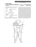
[0011] FIG. 1 is a perspective view of one embodiment of a collapsible thermal container and stand in an unfolded state;
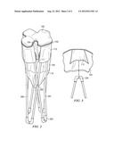
[0012] FIG. 2 is a perspective view of one embodiment of a collapsible thermal container and stand in a folded state;
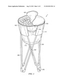
[0013] FIG. 3 is an enlarged sectional view of the collapsible thermal container and stand vertical member connection.
DETAILED DESCRIPTION OF THE INVENTION
[0014] FIG. 1 shows a perspective view of the collapsible thermal container and stand 1 according to an embodiment of this invention. The thermal container 100 is shown with its top 102 in a partially open position, partially sealed with an exemplary zipper 103. The top 102 covers a cylindrical body that is defined by an outer sidewall 104, and inner sidewall (not shown), with an insulator between the outer sidewall 104 and the inner sidewall. A thermal container bottom 110 is connected at the rim of the outer sidewall 104 opposite the top 102. A pair of loop handles 111 are joined to the outer sidewall 104 at two remote locations along the outer sidewall 104. These loop handles are formed from woven webs in this embodiment, but alternatively, other types of appropriate handle material can be employed. In one embodiment, the free ends of each of the loop handles 111 are joined to the sidewall by stitching, or another appropriate attachment mechanism.
[0015] As seen in FIG. 3, ice chest 100 has pockets 112 sized to fit over the top of the upper connector pads 204 of stand 200. Ice chest 100 is thereby supported and held in place by the stand 200 attached to thermal container 100 by pockets 112.
[0016] As seen in FIG. 2, thermal container 100 is collapsible in the horizontal plane. In order to collapse the thermal container when preparing for transport or storage, a user may press the side pockets 112 or other part of the thermal container in the horizontal direction to generate the compressed profile as shown in FIG. 2.
[0017] The size and shape of a collapsible thermal container in accordance with this invention is highly variable. As shown in FIG. 1, it can be dimensioned to hold a plurality of conventional drink cans. In one embodiment, the diameter of the thermal container is approximately 18 inches. However, other diameters, heights and shapes are expressly contemplated within the scope of this invention.
[0018] As shown in FIGS. 1-3, stand 200 has a frame comprised of four pair of crossed legs 201, which in this embodiment is made from tubular members. Each pair of crossed legs is pivotally connected at their approximate centers by a pivot pin 202. Each lower end of each leg of each pair of crossed legs is connected to the lower end of a one leg of an adjoining pair of crossed legs using lower connector pads 203. Each upper end of each leg of each pair of crossed legs is connected to the upper end of one leg of an adjoining pair of crossed legs using upper connector pads 204. Eight connector pads are provided, one at each lower corner and one at each upper corner of the stand at the end point of the pairs of crossed legs. Each lower connector pad 203 is pivotally connected in one plane to the lower end of one leg of one pair of the crossed legs and pivotally connected in the same plane to the lower end of a second crossed leg of another pair of the crossed legs. The lower ends of each pair of crossed legs is thereby connected to the lower connector pads 203. Each upper connector pad 204 is pivotally connected in one plane to the upper end of one leg of one pair of the crossed legs and pivotally connected in the same plane to the upper end of a second crossed leg of another pair of the crossed legs. The upper ends of each pair of crossed legs is thereby connected to the upper connector pads 204.
[0019] The connector pads 203 are identical. As shown in FIG. 3, each pad comprises a bottom surface, a connector pin, and two extending arms. Each extending arm is sized to snugly receive the end of one tubular member of said pair of crossed legs. The extending arms of the connector pads 203 and 204 are sized to allow a pivotal connection to the crossed legs and to permit the crossed legs to swing, thereby allowing the frame to fold and unfold. When the crossed legs are compressed together at the pivot pin and the connector pads permit the cross legs to swing together in a collapsed position, the collapsible thermal container is compressed by folds in the outer sidewalls, inner sidewalls, top, and bottom
[0020] In all embodiments, the collapsible thermal container and stand folds into a compact space and can be inserted into an appropriately sized bag for transport.
User Contributions:
Comment about this patent or add new information about this topic:
| People who visited this patent also read: | |
| Patent application number | Title |
|---|---|
| 20120210862 | BLAST-RESISTANT WINDOW |
| 20120210861 | SYSTEM FOR PROVIDING PROTECTION AGAINST AN EXPLOSIVE THREAT |
| 20120210860 | Pipe-shaped product with ballistic protection |
| 20120210859 | BREECH GUIDES FOR USE WITH BREECH ASSEMBLIES AND FIREARMS INCLUDING SUCH BREECH GUIDES |
| 20120210858 | FUZE INTERNAL OSCILLATOR CALIBRATION SYSTEM, METHOD, AND APPARATUS |
Images included with this patent application:
 |  |
 |
| Similar patent applications: | |
| Date | Title |
|---|---|
| 2013-02-21 | Collapsible semi-bulk container |
| 2012-10-04 | Collapsible locking container |
| 2010-11-04 | Convertible container and plate |
| 2011-04-14 | Convertible container and plate |
| 2012-07-26 | Collapsible containers |
| New patent applications in this class: | |
| Date | Title |
|---|---|
| 2016-05-12 | Thermally insulated vip sandwich shipper |
| 2016-03-31 | High efficiency bolt-on thermal insulating panel and thermally insulated shipping container employing such a thermal insulating panel |
| 2015-12-31 | Low temperature liquid tank |
| 2015-11-26 | Intermodal container and method of constructing same |
| 2015-04-30 | Lid structure for cooler |
| New patent applications from these inventors: | |
| Date | Title |
|---|---|
| 2011-07-21 | Collapsible garbage container |
| Top Inventors for class "Receptacles" | |
| Rank | Inventor's name |
|---|---|
| 1 | Daniel Lee Bizzell |
| 2 | Frank Yang |
| 3 | Terry Vovan |
| 4 | William P. Apps |
| 5 | Lowell L. Wood, Jr. |