Patent application title: REFRACTIVE, VARIABLE MAGNIFICATION OPTICAL SYSTEM
Inventors:
Setsu Sato (Saitama, JP)
IPC8 Class: AG02B1514FI
USPC Class:
359684
Class name: With variable magnification (e.g., zoom type) with mechanical compensation other than first group moves for focusing (internal focus type)
Publication date: 2012-07-12
Patent application number: 20120176685
Abstract:
A refractive, variable magnification optical system comprising,
sequentially from a side nearest an object, a first lens group having a
positive refractive power; a second lens group having a negative
refractive power; a third lens group having a positive refractive power;
and a fourth lens group having a positive refractive power. The first
lens group includes sequentially from the side nearest the object, a
negative meniscus lens having a convex surface facing toward the object,
a prism that refracts an optical path, a plano-convex lens, and a
biconvex lens, a light transmitting surface of the prism and the
plano-convex lens being cemented. The third lens group 3 includes the
aperture stop ST. The fourth lens group includes a meniscus lens that has
a concave surface facing toward an image plane and is disposed nearest
the image plane, among the lenses of the fourth lens group.Claims:
1. A refractive, variable magnification optical system comprising,
sequentially from a side nearest an object, a first lens group having a
positive refractive power; a second lens group having a negative
refractive power; a third lens group having a positive refractive power;
and a fourth lens group having a positive refractive power, wherein the
first lens group includes sequentially from the side nearest the object,
a negative meniscus lens having a convex surface facing toward the
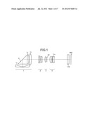
object, a prism that refracts an optical path, a plano-convex lens, and a
biconvex lens, a light transmitting surface of the prism and the
plano-convex lens being cemented, the fourth lens group includes a
meniscus lens that has a concave surface facing toward an image plane and
is disposed nearest the image plane, among the lenses of the fourth lens
group, the second lens group moves along an optical axis, from the side
nearest the object toward the image plane to zoom from a wide angle edge
to a telephoto edge, and the fourth lens group moves along the optical
axis to perform focusing.
2. The refractive, variable magnification optical system according to claim 1, wherein the following conditional expressions are satisfied: NdG03>NdG04 conditional expression (1) NdG04.ltoreq.1.65 conditional expression (2) νdG03<νdG04 conditional expression (3) νdG04.gtoreq.70 conditional expression (4) where, NdG03 is the refractive index at d-line of the plano-convex lens in the first lens group, NdG04 is the refractive index at the d-line of the biconvex lens in the first lens group, νdG03 is the Abbe number for the d-line of plano-convex lens in the first lens group, and νdG04 is the Abbe number for the d-line of the biconvex lens in the first lens group.
3. The refractive, variable magnification optical system according to claim 1, wherein the following conditional expressions are satisfied: -0.6>G01R02/fG01>-0.9 conditional expression (5) -1.1>G11R01/fG01>-1.7 conditional expression (6) where, G01R02 is the radius of curvature of the surface on the image plane side of the lens disposed nearest the object, among the lenses of the first lens group; fG01 is the focal length of the lens disposed nearest the object, among the lenses of the first lens group; and G11R01 is the radius of curvature of the surface on the object side of the lens disposed nearest the image plane, among the lenses of the fourth lens group.
4. The refractive, variable magnification optical system according to claim 1, wherein the fourth lens group includes a cemented lens having a meniscus shape.
5. The refractive, variable magnification optical system according to claim 1, wherein the following conditional expressions are satisfied: -0.09<FT/FAT<0.09 conditional expression (7) 2.0<F1/FW≦3.0 conditional expression (8) FW/Fe=0 conditional expression (9) where, FT is the focal length of the optical system, at the telephoto edge; FAT is the combined focal length of the first lens group to the third lens group, at the telephoto edge; F1 is the focal length of the first lens group; FW is the focal length of the optical system, at the wide angle edge; and Fe is the focal length of the lens disposed nearest the image plane, among the lenses of the fourth lens group.
6. The refractive, variable magnification optical system according to claim 1, wherein each lens of the first lens group, the third lens group, and the fourth lens group are made of a glass material.
7. The refractive, variable magnification optical system according to claim 1, wherein a lens nearest the object, among the lenses of the second lens group is made of a resin material.
Description:
BACKGROUND OF THE INVENTION
[0001] 1. Field of the Invention
[0002] The present invention relates to a compact refractive optical system having high optical performance and suitable for compact imaging apparatuses.
[0003] 2. Description of the Related Art
[0004] Accompanying demand for smaller imaging apparatuses, smaller imaging lenses mounted to the imaging apparatuses are also demanded. In response to this demand, a refractive optical system has been proposed that disposes in the optical path, a prism that refracts the optical path, thereby enabling a reduction in a dimension of depth (thickness) of the optical system. Consequently, by employing this refractive optical system, the thickness of the imaging device is also reduced. However, in recent years, in addition to the demand for even thinner digital cameras equipped with a refractive optical system, wider angles of view and higher resolution are also demanded. Further, with the correction of chromatic difference of magnification and distortion becoming possible via software applications, optical systems that assume the correction of aberration via software applications are also demanded. Consequently, optical systems capable of meeting such demands have also emerged (for example, refer to Japanese Patent Laid-Open Publication No. 2008-250135).
[0005] Although the optical system recited in Japanese Patent Laid-Open Publication No. 2008-250135 is compact, since numerous resin lenses are used, the optical system is easily affected by temperature changes such as those caused by the heat emitted by components such as an image sensor. For example, if the surrounding temperature increases, displacement of the image plane may occur consequent to thermal expansion of the lens.
[0006] In general, resin lenses are difficult to cut. For example, when a resin lens is formed "rectangularly" by an injection molding process, creating the shape of a proper lens surface is difficult.
[0007] Furthermore, the prism and the lens disposed near the image side of the prism are separate in the optical system recited in Japanese Patent Laid-Open Publication No. 2008-250135. Consequently, light reflected at a lower aspect of the prism may enter the optical path on the image side, resulting in ghosting.
SUMMARY OF THE INVENTION
[0008] It is an object of the present invention to at least solve the above problems in the conventional technologies.
[0009] A refractive, variable magnification optical system according to one aspect of the invention includes, sequentially from a side nearest an object, a first lens group having a positive refractive power; a second lens group having a negative refractive power; a third lens group having a positive refractive power; and a fourth lens group having a positive refractive power.
The first lens group includes sequentially from the side nearest the object, a negative meniscus lens having a convex surface facing toward the object, a prism that refracts an optical path, a plano-convex lens, and a biconvex lens, a light transmitting surface of the prism and the plano-convex lens being cemented. The third lens group 3 includes the aperture stop ST. The fourth lens group includes a meniscus lens that has a concave surface facing toward an image plane and is disposed nearest the image plane, among the lenses of the fourth lens group.
[0010] The other objects, features, and advantages of the present invention are specifically set forth in or will become apparent from the following detailed description of the invention when read in conjunction with the accompanying drawings.
BRIEF DESCRIPTION OF THE DRAWINGS
[0011] FIG. 1 is a diagram of the refractive, variable magnification optical system according to an embodiment of the present invention;
[0012] FIG. 2 is a cross sectional view (along the optical axis) of the refractive, variable magnification optical system according to a first example;
[0013] FIG. 3 is a diagram of aberration occurring at the wide angle edge of the refractive, variable magnification optical system according to the first example;
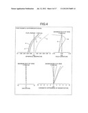
[0014] FIG. 4 is a diagram of aberration occurring at the intermediate edge of the refractive, variable magnification optical system according to the first example;
[0015] FIG. 5 is a diagram of aberration occurring at the telephoto edge of the refractive, variable magnification optical system according to the first example;
[0016] FIG. 6 is a cross sectional view (along the optical axis) of the refractive, variable magnification optical system according to a second example;
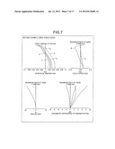
[0017] FIG. 7 is a diagram of aberration occurring at the wide angle edge of the refractive, variable magnification optical system according to the second example;
[0018] FIG. 8 is a diagram of aberration occurring at the intermediate edge of the refractive, variable magnification optical system according to the second example;
[0019] FIG. 9 is a diagram of aberration occurring at the telephoto edge of the refractive, variable magnification optical system according to the second example;
[0020] FIG. 10 is a cross sectional view (along the optical axis) of the refractive, variable magnification optical system according to a third example;
[0021] FIG. 11 is a diagram of aberration occurring at the wide angle edge of the refractive, variable magnification optical system according to the third example;
[0022] FIG. 12 is a diagram of aberration occurring at the intermediate edge of the refractive, variable magnification optical system according to the third example;
[0023] FIG. 13 is a diagram of aberration occurring at the telephoto edge of the refractive, variable magnification optical system according to the third example;
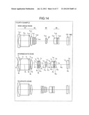
[0024] FIG. 14 is a cross sectional view (along the optical axis) of the refractive, variable magnification optical system according to a fourth example;
[0025] FIG. 15 is a diagram of aberration occurring at the wide angle edge of the refractive, variable magnification optical system according to the fourth example;
[0026] FIG. 16 is a diagram of aberration occurring at the intermediate edge of the refractive, variable magnification optical system according to the fourth example; and
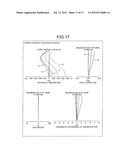
[0027] FIG. 17 is a diagram of aberration occurring at the telephoto edge of the refractive, variable magnification optical system according to the fourth example.
DETAILED DESCRIPTION OF THE PREFERRED EMBODIMENTS
[0028] Referring to the accompanying drawings, exemplary embodiments according to the present invention are explained in detail below.
[0029] Referring to the accompanying drawings, exemplary embodiments of a refractive, variable magnification optical system according to the present invention are explained in detail below.
[0030] FIG. 1 is a diagram of the refractive, variable magnification optical system according to an embodiment of the present invention. The refractive, variable magnification optical system includes sequentially from a side nearest the object (not depicted), a first lens group 1 having a positive refractive power, a second lens group 2 having a negative refractive power, a third lens group 3 having a positive refractive power, and a fourth lens group 4 having a positive refractive power. Further, a cover glass CG is disposed between the fourth lens group 4 and an image plane IMG. The refractive, variable magnification optical system zooms from the wide angle edge to the telephoto edge by moving the second lens group 2 along the optical axis, from the object side toward the image plane IMG side; and performs focusing by moving the fourth lens 4 along the optical axis. The first lens group 1 and the third lens group 3 are fixed.
[0031] The first lens group 1 includes sequentially from the object side, negative meniscus lens L1 having a convex surface facing toward the object, a prism P1 that refracts the optical path, a plano-convex lens L2, and a biconvex lens L3. A light transmitting surface of the prism P1 and the plano-convex lens L2 are cemented. The third lens group 3 is configured to include an aperture stop ST. Although FIG. 1 depicts an example where the aperture stop ST is disposed on the image side of a lens making up the third lens group 3, provided the aperture stop ST is near the lens, the aperture stop ST may be disposed on the object side of the lens. A meniscus lens L10 having a concave surface on the image plane side is disposed nearest the image plane IMG, among the lenses of the fourth lens group 4.
[0032] By disposing the negative meniscus lens L1 (which has a convex surface on the object side) nearest the object among the lenses of the first lens group 1, the occurrence of various types of aberration, such as distortion, can be suppressed. The prism P1, the plano-convex lens L2, and the biconvex lens L3 are disposed subsequent to the meniscus lens L1, and by cementing the light transmitting surface of the prism P1 and the plano-convex lens L2, a shortening of a dimension of depth (thickness) of the optical system is enabled and the occurrence of ghosting consequent to light reflected at a lower aspect of the prism P1 can be suppressed. Further, by disposing the meniscus lens L10 (which has a concave surface on the image plane IMG side) nearest the image plane IMG, among the lenses of the fourth lens group 4, coma that is in an opposite direction to that of the coma caused by the meniscus lens L1 is created by the meniscus lens L10, enabling cancellation of the coma caused by the meniscus lens L1.
[0033] An object of the present invention is to provide a refractive, variable magnification optical system that is resistant to temperature changes, is thin and compact, and offers high optical performance at wide angles. To further assure achievement of the object, in addition to the characteristics above, the following conditions are further set with respect to the present invention.
[0034] The refractive, variable magnification optical system according to the present embodiment preferably satisfies the following conditional expressions, where NdG03 is the refractive index at the d-line of the plano-convex lens L2 in the first lens group 1, NdG04 is the refractive index at the d-line of the biconvex lens L3 in the first lens group 1, νdG03 is the Abbe number for the d-line of the plano-convex lens L2 in the first lens group 1, and νdG04 is the Abbe number for the d-line of the biconvex lens L3 in the first lens group 1.
NdG03>NdG04 (1)
NdG04≦1.65 (2)
νdG03<νdG04 (3)
νdG04≧70 (4)
[0035] Satisfaction of conditional expression (1) to (4) corrects, in a balanced manner, longitudinal chromatic aberration occurring at the telephoto edge of the refractive, variable magnification optical system and chromatic difference of magnification occurring at the wide angle edge, enabling improvement of the imaging performance of the optical system.
[0036] The refractive, variable magnification optical system according to the embodiment preferably satisfies the following conditional expressions, where G01R02 is the radius of curvature of the surface on the image plane IMG side of the lens (meniscus lens 1) disposed nearest the object, among the lenses of the first lens group 1; fG01 is the focal length of the lens (meniscus lens 1) disposed nearest the object, among the lenses of the first lens group 1; and G11R01 is the radius of curvature of the surface on the object side of the lens (meniscus lens L10) disposed nearest the image plane IMG among the lenses of the fourth lens group 4.
-0.6>G01R02/fG01>-0.9 (5)
-1.1>G11R01/fG01>-1.7 (6)
[0037] Satisfaction of conditional expression (5) and (6) accurately corrects coma of the intermediate image height occurring at the telephoto edge of the refractive, variable magnification optical system, and enables radial distortion occurring at the wide angle edge to be prevented. If the refractive, variable magnification optical system is outside either one of the ranges prescribed by conditional expressions (5) and (6), the correction of coma of the intermediate image height occurring at the telephoto edge becomes difficult, or radial distortion at the wide angle occurs. In particular, an occurrence of radial distortion invites a drop in the modulation transfer function (MTF).
[0038] Further, in the refractive, variable magnification optical system, a meniscus-shaped cemented lens is may be disposed on the object side of the meniscus lens L10 in the fourth lens group 4. By such a configuration, correction of the coma occurring at the meniscus lens L1 can be performed by the cemented lens in place of the meniscus lens L10. In this manner, correction of the coma at the meniscus lens L1 can be assumed by the cemented lens, whereby the axial shift tolerance of the meniscus lens L10 can be less strict, facilitating optical system design.
[0039] The refractive, variable magnification optical system according to the embodiment preferably satisfies the conditional expressions below, where FT is the focal length of the entire optical system, at the telephoto edge; FAT is the combined focal length of the first lens group 1 to the third lens group 3, at the telephoto edge; F1 is the focal length of the first lens group 1; FW is the focal length of the entire optical system, at the wide angle edge; and Fe is the focal length of the lens (meniscus lens L10) disposed nearest the image plane IMG, among the lenses of the fourth lens group 4.
-0.09<FT/FAT<0.09 (7)
2.0<F1/FW≦3.0 (8)
FW/Fe=0 (9)
[0040] Conditional expression (7) prescribes a condition for preventing deterioration of optical performance during focusing. Satisfaction of conditional expression (7) enables effective correction of various types of aberration that occur during focusing. Outside the range prescribed by conditional expression (7), aberration that occurs during focusing becomes prominent and is thus, not desirable.
[0041] Conditional expression (8) expresses a condition for reducing the overall length of the optical system and for correcting, in a balanced manner, longitudinal chromatic aberration occurring at the telephoto edge and chromatic difference of magnification occurring at the wide angle edge. Satisfaction of conditional expression (8) enables the refractive, variable magnification optical system to correct, in a balanced manner, longitudinal chromatic aberration occurring at the telephoto edge and chromatic difference of magnification occurring at the wide angle edge and further enables the overall length of the optical system to be reduced. Below the lower limit of conditional expression (8), the overall length of the optical system cannot be reduced and is thus, not desirable. On the other hand, above the upper limit of conditional expression (8), longitudinal chromatic aberration occurring at the telephoto edge and chromatic difference of magnification occurring at the wide angle edge become prominent and is thus, not desirable.
[0042] Conditional expression (9) expresses a condition for making the tolerance of the surface intervals of lens (meniscus lens L10) disposed nearest the image plane IMG, among the lenses of the fourth lens group 4, less strict. By satisfying conditional expression (9), the paraxial refractive power of the meniscus lens L10 becomes 0, thereby enabling the surface interval tolerance of the meniscus lens L10 to be less strict and thus, facilitating optical system design. When Fe=0, then FW=∞. Satisfaction of conditional expressions (7) to (9) facilitates design and enables a compact refractive, variable magnification optical system having high optical performance to be provided.
[0043] In the refractive, variable magnification optical system according to the embodiment, the lenses of the first lens group 1, the third lens group 3, and the fourth lens group 4 may be made of a glass material. Further, the first lens group 1 includes a large diameter lens to enable a greater wide-angle view. The first lens group 1 further includes the prism P1, whereby the optical path is refracted, facilitating contact of the outer peripheral portions of the meniscus lens L1 and the biconvex lens L3, and attempts to prevent this contact may be detrimental to reducing the dimension of depth (thickness) of the optical system. Thus, to prevent such disadvantages, a D-cut of the lens is necessary, the use of a lens formed by a glass material, which is easy to form the D-cut, is preferable. Forming each of the lenses of the first lens group 1 of a glass material facilitates the D-cut of the meniscus lens L1 and the biconvex lens L3. By implementing a D-cut of meniscus lens L1 and biconvex lens L3, the outer peripheral portions of the meniscus lens L1 and the biconvex lens L3, which are disposed on the refracted optical path, can be prevented from interfering with one another, fostering a reduction in the thickness of the optical system. On the other hand, since the third lens group 3 and the fourth lens group 4 are relatively close to the image sensor, which is a source of heat, the third lens group 3 and the fourth lens group 4 are configured by lenses made of a glass material, which is resistant to temperature changes, thereby enabling displacement of the image plane consequent to thermal expansion of the lenses to be prevented. Of course, all of the lens groups may be configured by lenses made of a glass material.
[0044] In the refractive, variable magnification optical system, the lens disposed nearest the object, among the lenses of the second lens group 2 may be made of a resin material. The lens disposed nearest the object, among the lenses of the second lens group 2 need not be subject to the D-cut for enabling a shape having a smaller effective diameter and since the lenses are disposed away from the heat generating image sensor, the lenses are not susceptible to temperature changes. Therefore, by forming the lens of a resin material, the manufacturing cost can be reduced. A further advantage is that when an aspheric surface has to be formed on a lens, a resin lens facilitates formation of an aspheric surface.
[0045] As described, the refractive, variable magnification optical system according to the embodiment has the characteristics described above, thereby forming a thin and compact refractive, variable magnification optical system having high optical performance at a wide-angle view. In particular, by satisfying the conditional expressions above, imaging performance can be further improved. Further, making each of the lenses configuring the first lens group 1 of a glass material facilitates further reduction of thickness of the optical system. By additionally making each of the lenses configuring the third lens group 3 and the fourth lens group 4, which are susceptible to the effects of heat, of a glass material, displacement of the image plane consequent to thermal expansion of the lenses can be prevented.
[0046] Hereinafter, examples of the refractive, variable magnification optical system according to the present invention will be described in detail with reference to the accompanying drawings. The present invention is not limited by the following examples.
[0047] FIG. 2 is a cross sectional view (along the optical axis) of the refractive, variable magnification optical system according to a first example. The refractive, variable magnification optical system includes sequentially from a side nearest the object (not depicted), a first lens group 11 having a positive refractive power, a second lens group 12 having a negative refractive power, a third lens group 13 having a positive refractive power, and a fourth lens group 14 having a positive refractive power. Further, the cover glass CG is disposed between the fourth lens group 14 and the image plane IMG. The cover glass CG is disposed as needed and when not necessary, may be omitted. Further, at the image plane IMG, the optical receiving surface of the image sensor, such as a CCD, CMOS, etc. is disposed.
[0048] The first lens group 11 includes sequentially from the object side, a negative meniscus lens L111 having a convex surface facing toward the object, a prism P11 that refracts the optical path, a plano-convex lens L112, and a biconvex lens L113. The light transmitting surface of the prism P11 and the plano-convex lens L112 are cemented. The meniscus lens L111, the plano-convex lens L112, and the biconvex lens L113 are made of a glass material and have a D-cut. Further, the surface of the object side of the meniscus lens L111 and of the biconvex lens L113 are aspheric, respectively.
[0049] The second lens group 12 includes sequentially from the object side, a negative lens L121, a negative lens L122, and a positive lens L123. These lenses are each made of a glass material. The negative lens L122 and the positive lens L123 are cemented. Further, the surface of the object side of the negative lens L121 is aspheric.
[0050] The third lens group 13 includes sequentially from the object side, a positive lens L131 and the aperture stop ST of a prescribed diameter. The positive lens L131 is made of a glass material. Further, the surface of the object side of the positive lens L131 is aspheric.
[0051] The fourth lens group 14 includes a positive lens L141, a negative lens L142, and a meniscus lens L143 having a concave surface facing toward the image plane IMG. These lenses are each made of a glass material. The positive lens L141 and the negative lens L142 are cemented and collectively have a meniscus shape. Further, the surface of the object side of the meniscus lens L143 is aspheric.
[0052] The refractive, variable magnification optical system zooms from the wide angle edge to the telephoto edge by moving the second lens group 12 along the optical axis, from the object side toward the image plane IMG side; and performs focusing by moving the fourth lens group 14 along the optical axis. The first lens group 11 and the third lens group 13 are fixed.
[0053] Various values related to the refractive, variable magnification optical system according to the first example are indicated below.
Focal length=5.2 (FW: wide angle edge) to 8.98 (intermediate edge) to 16.16 (FT: telephoto edge) F-number=3.64 (wide angle edge) to 4.00 (intermediate edge) to 4.24 (telephoto edge) Angle of view (2ω)=72.2° (wide angle edge) to 46.2° (intermediate edge) to 25.64° (telephoto edge)
(Values Related to Conditional Expressions (1) to (4))
[0054] Refractive index at d-line of plano-convex lens L112 (NdG03)=1.75 Refractive index at d-line of biconvex lens L113 (NdG04)=1.50
(∴NdG03>NdG04, NdG04≦1.55)
[0055] Abbe number for d-line of plano-convex lens L112 (νdG03)=52.32 Abbe number for d-line of biconvex lens L113 (νdG04)=81.61 (∴νdG03<νdG04, νdG04≧70)
(Values Related to Conditional Expressions (5) and (6))
[0056] Radius of curvature of image plane IMG side of meniscus lens L111 (G01R02)=9.04 Focal length of meniscus lens L111 (fG01)=-11.13 Radius of curvature of object side of meniscus lens L143 (G11R01)=17.72 G01R02/fG01=-0.81 G11R01/fG01=-1.59
(Values Related to Conditional Expressions (7) to (9))
[0057] Combined focal length of first lens group 11 to third lens 13 group, at telephoto edge (FAT)=198.8 Focal length of first lens group 11 (F1)=13.02 Focal length of meniscus lens L143 (Fe)=1×1069
FT/FAT=0.081
F1/FW=3
FW/Fe=0
[0058] r1=86.60 (aspheric surface)
[0059] d1=0.50 nd1=1.90 νd1=31.01
r2=9.04
[0060] d2=1.91
r3=∞ (prism surface)
[0061] d3=7.30 nd2=1.90 νd2=31.32
r4=∞
[0062] d4=1.27 nd3=1.75 νd3=52.32
r5=-16.08
[0063] d5=0.10
r6=13.73 (aspheric surface)
[0064] d6=1.86 nd4=1.50 νd4=81.61
r7=-21.75
[0065] d7=0.5 (wide angle edge) to 3.936 (intermediate edge) to 7.317 (telephoto edge)
r8=-14.71 (aspheric surface)
[0066] d8=0.50 nd5=1.52 νd5=64.07
r9=13.45
[0067] d9=0.76
r10=-13.01
[0068] d10=0.50 nd6=1.84 νd6=42.98
r11=7.55
[0069] d11=0.84 nd7=1.92 νd7=18.90
r12=30.58
[0070] d12=7.317 (wide angle edge) to 3.855 (intermediate edge) to 0.5 (telephoto edge)
r13=7.48 (aspheric surface)
[0071] d13=0.90 nd8=1.50 νd8=81.56
r14=-50.61
[0072] d14=0.70
r15=∞ (aperture stop)
[0073] d15=5.293 (wide angle edge) to 3.152 (intermediate edge) to 1.975 (telephoto edge)
r16=6.93
[0074] d16=1.46 nd9=1.74 νd9=44.79
r17=-29.87
[0075] d17=0.50 nd10=1.95 νd10=17.98
r18=17.90
[0076] d18=0.10
r19=17.72 (aspheric surface)
[0077] d19=1.23 nd11=1.52 νd11=64.07
r20=17.72
[0078] d20=7 (wide angle edge) to 9.141 (intermediate edge) to 10.318 (telephoto edge)
r21=∞
[0079] d21=1.40 nd12=1.52 νd12=64.14
r22=∞ Constant of the cone (ε) and aspheric coefficients (A, B, C, D, E, F, G, H, I)
[0080] (First Plane)
ε=23.366,
A=0, B=0,
C=2.062111×10⁻⁶, D=1.074871×10⁻⁶,
E=2.102009×10⁻⁸, F=1.275181×10⁻⁹,
G=-3.936452×10⁻¹¹, H=0,
I=0
[0081] (Sixth Plane)
δ=0.703,
A=0, B=-1.784580×10⁻⁵,
C=-1.687408×10⁻⁴, D=-6.085992×10⁻⁶,
E=-1.244994×10⁻⁷, F=-1.863924×10⁻⁹,
G=2.560434×10⁻¹⁰, H=-9.172798×10⁻¹²,
I=0
[0082] (Eighth Plane)
ε=-46.267,
A=0, B=0,
C=5.594144×10⁻⁴, D=-6.314570×10⁻⁵,
E=-2.321334×10⁻⁸, F=6.996445×10⁻⁸,
G=2.360671×10⁻⁸, H=0,
I=0
[0083] (Thirteenth Plane)
ε=1.457,
A=0, B=0,
C=-1.035791×10⁻⁴, D=2.808004×10⁻⁶,
E=4.999901×10⁻⁶, F=2.229841×10⁻⁶,
G=-8.607045×10⁻⁸, H=0,
I=0
[0084] (Nineteenth Plane)
ε=23.397,
A=0, B=0,
C=2.233456×10⁻³, D=1.116136×10⁻⁵,
E=-3.810640×10⁻⁸, F=5.491464×10⁻⁸,
G=-3.588824×10⁻⁸, H=0,
I=0
[0085] FIG. 3 is a diagram of aberration occurring at the wide angle edge of the refractive, variable magnification optical system according to the first example. FIG. 4 is a diagram of aberration occurring at the intermediate edge of the refractive, variable magnification optical system according to the first example. FIG. 5 is a diagram of aberration occurring at the telephoto edge of the refractive, variable magnification optical system according to the first example. In the diagrams, d indicates chromatic aberration corresponding to the d-line (λ=588 nm), g indicates chromatic aberration corresponding to the g-line (λ=436 nm), F indicates chromatic aberration corresponding to the F-line (λ=486 nm), C indicates chromatic aberration corresponding to the C-line (λ=656 nm), and e indicates chromatic aberration corresponding to the e-line (λ=546 nm). Reference numerals S and M in a field of curvature diagram indicate aberration for the sagittal plane and the meridonal plane, respectively.
[0086] FIG. 6 is a cross sectional view (along the optical axis) of the refractive, variable magnification optical system according to a second example. The refractive, variable magnification optical system includes sequentially from a side nearest the object (not depicted), a first lens group 21 having a positive refractive power, a second lens group 22 having a negative refractive power, a third lens group 23 having a positive refractive power, and a fourth lens group 24 having a positive refractive power Further, the cover glass CG is disposed between the fourth lens group 24 and the image plane IMG. The cover glass CG is disposed as needed and when not necessary, may be omitted. Further, at the image plane IMG, the optical receiving surface of the image sensor, such as a CCD, CMOS, etc. is disposed.
[0087] The first lens group 21 includes sequentially from the object side, a negative meniscus lens L211 having a convex surface facing toward the object, a prism P21 that refracts the optical path, a plano-convex lens L212, and a biconvex lens L213. The light transmitting surface of the prism P21 and the plano-convex lens L212 are cemented. The meniscus lens L211, the plano-convex lens L212, and the biconvex lens L213 are made of a glass material and have a D-cut. Further, the surface of the object side of the meniscus lens L211 and of the biconvex lens L213 are aspheric, respectively.
[0088] The second lens group 22 includes sequentially from the object side, a negative lens L221, a negative lens L222, and a positive lens L223. These lenses are each made of a glass material. The negative lens L222 and the positive lens L223 are cemented. Further, the surface of the object side of the negative lens L221 is aspheric.
[0089] The third lens group 23 includes sequentially from the object side, a positive lens L231 and the aperture stop ST of a prescribed diameter. The positive lens L231 is made of a glass material. Further, the surface of the object side of the positive lens L231 is aspheric.
[0090] The fourth lens group 24 includes a positive lens L241, a negative lens L242, and a meniscus lens L243 having a concave surface facing toward the image plane IMG. These lenses are each made of a glass material. The positive lens L241 and the negative lens L242 are cemented and collectively have a meniscus shape. Further, the surface of the object side of the meniscus lens L243 is aspheric.
[0091] The refractive, variable magnification optical system zooms from the wide angle edge to the telephoto edge by moving the second lens group 22 along the optical axis, from the object side toward the image plane IMG side; and performs focusing by moving the fourth lens group 24 along the optical axis. The first lens group 21 and the third lens group 23 are fixed.
[0092] Various values related to the refractive, variable magnification optical system according to the second example are indicated below.
Focal length=5.08 (FW: wide angle edge) to 9.66 (intermediate edge) to 18.57 (FT: telephoto edge) F-number=3.62 (wide angle edge) to 4.09 (intermediate edge) to 4.398 (telephoto edge) Angle of view (2ω)=73.5° (wide angle edge) to 42.88° (intermediate edge) to 23.10° (telephoto edge)
(Values Related to Conditional Expressions (1) to (4))
[0093] Refractive index at d-line of plano-convex lens L212 (NdG03)=1.75 Refractive index at d-line of biconvex lens L213 (NdG04)=1.50
(∴NdG03>NdG04, NdG04≦1.55)
[0094] Abbe number for d-line of plano-convex lens L212 (νdG03)=52.32 Abbe number for d-line of biconvex lens L213 (νdG04)=81.61 (∴νdG03<νdG04, νdG04≧70)
(Values Related to Conditional Expressions (5) and (6))
[0095] Radius of curvature of image plane IMG side of meniscus lens L211 (G01R02)=9.42 Focal length of meniscus lens L211 (fG01)=-11.84 Radius of curvature of object side of meniscus lens L243 (G11R01)=14.48 G01R02/fG01=-0.80 G11R01/fG01=-1.22
(Values Related to Conditional Expressions (7) to (9))
[0096] Combined focal length of first lens group 21 to third lens group 23, at telephoto edge (FAT)=-930.5 Focal length of first lens group 21 (F1)=13.447 Focal length of meniscus lens L243 (Fe)=1×1056
FT/FAT=-0.020
F1/FW=3
FW/Fe=0
[0097] r1=77.43 (aspheric surface)
[0098] d1=0.50 nd1=1.90 νd1=31.01
r2=9.42
[0099] d2=2.11
r3=∞ (prism surface)
[0100] d3=7.30 nd2=1.90 νd2=31.32
r4=∞
[0101] d4=1.32 nd3=1.75 νd3=52.32
r5=-16.91
[0102] d5=0.1
r6=14.09 (aspheric surface)
[0103] d6=1.79 nd4=1.50 νd4=81.61
r7=-22.64
[0104] d7=0.5 (wide angle edge) to 4.528 (intermediate edge) to 8.184 (telephoto edge)
r8=-14.42 (aspheric surface)
[0105] d8=0.50 nd5=1.52 νd5=64.07
r9=13.55
[0106] d9=0.81
r10=-12.92
[0107] d10=0.50 nd6=1.84 νd6=42.98
r11=8.09
[0108] d11=1.10 nd7=1.92 νd7=18.90
r12=31.29
[0109] d12=8.184 (wide angle edge) to 4.17 (intermediate edge) to 0.5 (telephoto edge)
r13=8.31 (aspheric surface)
[0110] d13=0.91 nd8=1.50 νd8=81.56
r14=-55.24
[0111] d14=0.70
r15=∞ (aperture stop)
[0112] d18=5.776 (wide angle edge) to 3.207 (intermediate edge) to 1.923 (telephoto edge)
r16=7.25
[0113] d16=2.70 nd9=1.74 νd9=44.79
r17=-22.37
[0114] d17=0.50 nd10=1.95 νd10=17.98
r18=19.70
[0115] d18=0.10
r19=14.48 (aspheric surface)
[0116] d19=1.23 nd11=1.52 νd11=64.07
r20=14.48
[0117] d20=7.35 (wide angle edge) to 9.19 (intermediate edge) to 11.27 (telephoto edge)
r21=∞
[0118] d21=1.50 nd12=1.52 νd12=64.14
r22=∞ Constant of the cone (δ) and aspheric coefficients (A, B, C, D, E, F, G, H, I)
[0119] (First Plane)
ε=49.286,
A=0, B=0,
C=5.13831×10⁻⁶, D=6.59077×10⁻⁷,
E=4.07767×10⁻⁹, F=8.99232×10⁻¹⁰,
G=1.75806×10⁻¹¹, H=0,
I=0
[0120] (Sixth Plane)
ε=0.863,
A=0, B=0,
C=-1.723238×10⁻⁴, D=2.940574×10⁻⁶,
E=8.824989×10⁻⁸, F=3.626982×10⁻⁹,
G=3.961153×10⁻¹⁰, H=0,
I=0
[0121] (Eighth Plane)
ε=-44.618,
A=0, B=0,
C=6.211540×10⁻⁴, D=4.358065×10⁻⁵,
E=-3.974179×10⁻⁷, F=1.512230×10⁻⁷,
G=-3.702931×10⁻⁹, H=0,
I=0
[0122] (Thirteenth Plane)
ε=3.019,
A=0, B=0,
C=-2.254315×10⁻⁴, D=2.930539×10⁻⁵,
E=5.091106×10⁻⁶, F=1.398557×10⁻⁶,
G=8.629026×10⁻⁸, H=0,
I=0
[0123] (Nineteenth Plane)
ε=20.610,
A=0, B=0,
C=1.776220×10⁻³, D=-1.214843×10⁻⁴,
E=5.125124×10⁻⁶, F=1.909264×10⁻⁶,
G=2.648721×10⁻⁷, H=0,
I=0
[0124] FIG. 7 is a diagram of aberration occurring at the wide angle edge of the refractive, variable magnification optical system according to the second example. FIG. 8 is a diagram of aberration occurring at the intermediate edge of the refractive, variable magnification optical system according to the second example. FIG. 9 is a diagram of aberration occurring at the telephoto edge of the refractive, variable magnification optical system according to the second example. In the diagrams, d indicates chromatic aberration corresponding to the d-line (λ=588 nm), g indicates chromatic aberration corresponding to the g-line (λ=436 nm), F indicates chromatic aberration corresponding to the F-line (λ=486 nm), C indicates chromatic aberration corresponding to the C-line (λ=656 nm), and e indicates chromatic aberration corresponding to the e-line (λ=546 nm). Reference numerals S and M in a field of curvature diagram indicate aberration for the sagittal plane and the meridonal plane, respectively.
[0125] FIG. 10 is a cross sectional view (along the optical axis) of the refractive, variable magnification optical system according to a third example. The refractive, variable magnification optical system includes sequentially from a side nearest the object (not depicted), a first lens group 31 having a positive refractive power, a second lens group 32 having a negative refractive power, a third lens group 33 having a positive refractive power, and a fourth lens group 34 having a positive refractive power. Further, the cover glass CG is disposed between the fourth lens group 34 and the image plane IMG. The cover glass CG is disposed as needed and when not necessary, may be omitted. Further, at the image plane IMG, the optical receiving surface of the image sensor, such as a CCD, CMOS, etc. is disposed.
[0126] The first lens group 31 includes sequentially from the object side, a negative meniscus lens L311 having a convex surface facing toward the object, a prism P31 that refracts the optical path, a plano-convex lens L312, and a biconvex lens L313. The light transmitting surface of the prism P31 and the plano-convex lens L312 are cemented. The meniscus lens L311, the plano-convex lens L312, and the biconvex lens L313 are made of a glass material and have a D-cut. Further, the surface of the object side of the meniscus lens L311 and of the biconvex lens L313 are aspheric, respectively.
[0127] The second lens group 32 includes sequentially from the object side, a negative lens L321, a negative lens L322, and a positive lens L323. These lenses are each made of a glass material. The negative lens L322 and the positive lens L323 are cemented. Further, the surface of the object side of the negative lens L321 is aspheric.
[0128] The third lens group 33 includes sequentially from the object side, a positive lens L331 and the aperture stop ST of a prescribed diameter. The positive lens L331 is made of a glass material. Further, the surface of the object side of the positive lens L331 is aspheric.
[0129] The fourth lens group 34 includes a positive lens L341, a negative lens L342, and a meniscus lens L343 having a concave surface facing toward the image plane IMG. These lenses are each made of a glass material. The positive lens L341 and the negative lens L342 are cemented and collectively have a meniscus shape. Further, the surface of the object side of the meniscus lens L343 is aspheric.
[0130] The refractive, variable magnification optical system zooms from the wide angle edge to the telephoto edge by moving the second lens group 32 along the optical axis, from the object side toward the image plane IMG side; and performs focusing by moving the fourth lens group 34 along the optical axis. The first lens group 31 and the third lens group 33 are fixed.
[0131] Various values related to the refractive, variable magnification optical system according to the third example are indicated below.
Focal length=5.03 (FW: wide angle edge) to 8.87 (intermediate edge) to 16.14 (FT: telephoto edge) F-number=3.62 (wide angle edge) to 3.96 (intermediate edge) to 4.16 (telephoto edge) Angle of view (2ω)=76.37° (wide angle edge) to 46.4° (intermediate edge) to 25.54° (telephoto edge)
(Values Related to Conditional Expressions (1) to (4))
[0132] Refractive index at d-line of plano-convex lens L312 (NdG03)=1.75 Refractive index at d-line of biconvex lens L313 (NdG04)=1.50
(∴NdG03>NdG04, NdG04≦1.55)
[0133] Abbe number for d-line of plano-convex lens L312 (νdG03)=52.32 Abbe number for d-line of biconvex lens L313 (νdG04)=81.61 (∴νdG03<νdG04, νdG04≧70)
(Values Related to Conditional Expressions (5) and (6))
[0134] Radius of curvature of image plane IMG side of meniscus lens L311 (G01R02)=8.956 Focal length of meniscus lens L311 (fG01)=-11.14 Radius of curvature of object side of meniscus lens L343 (G11R01)=16.737 G01R02/fG01=-0.80 G11R01/fG01=-1.50
(Values Related to Conditional Expressions (7) to (9))
[0135] Combined focal length of first lens group 31 to third lens group 33, at telephoto edge (FAT)=309.3 Focal length of first lens group 31 (F1)=12.92 Focal length of meniscus lens L343 (Fe)=1×1056
FT/FAT=0.052
F1/FW=3
FW/Fe=0
[0136] r1=79.307 (aspheric surface)
[0137] d1=0.50 nd1=1.90 νd1=31.01
r2=8.956
[0138] d2=2.01
r3=∞ (prism surface)
[0139] d3=7.20 nd2=1.90 νd2=31.32
r4=∞
[0140] d4=1.17 nd3=1.75 νd3=52.32
r5=-16.105
[0141] d5=0.10
r6=13.566 (aspheric surface)
[0142] d6=1.72 nd4=1.50 νd4=81.61
r7=-21.767
[0143] d7=0.5 (wide angle edge) to 4.061 (intermediate edge) to 7.486 (telephoto edge)
r8=-14.933 (aspheric surface)
[0144] d8=0.50 nd5=1.52 νd5=64.07
r9=13.651
[0145] d9=0.76
r10=-12.761
[0146] d10=0.50 nd6=1.84 νd6=42.98
r11=7.843
[0147] d11=0.96 nd7=1.92 νd7=18.90
r12=30.112
[0148] d12=7.486 (wide angle edge) to 3.924 (intermediate edge) to 0.5 (telephoto edge)
r13=7.712 (aspheric surface)
[0149] d13=0.90 nd8=1.50 νd8=81.56
r14=-53.504
[0150] d14=0.70
r15=∞ (aperture stop)
[0151] d15=5.244 (wide angle edge) to 3.169 (intermediate edge) to 2.153 (telephoto edge)
r16=6.835
[0152] d16=1.95 nd9=1.73 νd9=54.68
r17=-23.633
[0153] d17=0.50 nd10=1.92 νd10=20.88
r18=18.632
[0154] d18=0.10
r19=16.737 (aspheric surface)
[0155] d19=1.15 nd11=1.52 νd11=64.07
r20=16.737
[0156] d20=7.0 (wide angle edge) to 9.029 (intermediate edge) to 10.066 (telephoto edge)
r21=∞
[0157] d21=1.60 nd12=1.52 νd12=64.14
r22=∞ Constant of the cone (ε) and aspheric coefficients (A, B, C, D, E, F, G, H, I)
[0158] (First Plane)
ε=48.833,
A=0, B=0,
C=4.763680×10⁻⁷, D=1.030896×10⁻⁶,
E=3.576936×10⁻⁸, F=1.568245×10⁻⁹,
G=-4.598832×10⁻¹¹, H=0,
I=0
[0159] (Sixth Plane)
ε=0.709,
A=0, B=-2.217521,
C=-1.666536×10⁻⁴, D=-6.056760,
E=-1.254824, F=-1.876774,
G=2.520833×10⁻¹, H=-9.278857×10⁻¹,
I=0
[0160] (Eighth Plane)
ε=-50.024,
A=0, B=0,
C=5.579515×10⁻⁴, D=-5.687555×10⁻⁵,
E=1.036087×10⁻⁷, F=1.145889×10⁻⁷,
G=6.271237×10⁻⁹, H=0,
I=0
[0161] (Thirteenth Plane)
ε=0.957,
A=0, B=0,
C=-7.524246×10⁻⁶, D=1.639468×10⁻⁵,
E=5.324911×10⁻⁶, F=1.755133×10⁻⁶,
G=-2.774733×10⁻⁸, H=0,
I=0
[0162] (Nineteenth Plane)
ε=20.468,
A=0, B=0,
C=2.158511×10⁻³, D=3.962780×10⁻⁷,
E=-3.029426×10⁻⁶, F=1.478558×10⁻⁷,
G=-6.775195×10⁻⁸, H=0,
I=0
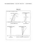
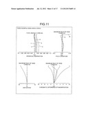
[0163] FIG. 11 is a diagram of aberration occurring at the wide angle edge of the refractive, variable magnification optical system according to the third example. FIG. 12 is a diagram of aberration occurring at the intermediate edge of the refractive, variable magnification optical system according to the third example. FIG. 13 is a diagram of aberration occurring at the telephoto edge of the refractive, variable magnification optical system according to the third example. In the diagrams, d indicates chromatic aberration corresponding to the d-line (λ=588 nm), g indicates chromatic aberration corresponding to the g-line (λ=436 nm), F indicates chromatic aberration corresponding to the F-line (λ=486 nm), C indicates chromatic aberration corresponding to the C-line (λ=656 nm), and e indicates chromatic aberration corresponding to the e-line (λ=546 nm). Reference numerals S and M in a field of curvature diagram indicate aberration for the sagittal plane and the meridonal plane, respectively.
[0164] FIG. 14 is a cross sectional view (along the optical axis) of the refractive, variable magnification optical system according to a fourth example. The refractive, variable magnification optical system includes sequentially from a side nearest the object (not depicted), a first lens group 41 having a positive refractive power, a second lens group 42 having a negative refractive power, a third lens group 43 having a positive refractive power, and a fourth lens group 44 having a positive refractive power. Further, the cover glass CG is disposed between the fourth lens group 44 and the image plane IMG. The cover glass CG is disposed as needed and when not necessary, may be omitted. Further, at the image plane IMG, the optical receiving surface of the image sensor, such as a CCD, CMOS, etc. is disposed.
[0165] The first lens group 41 includes sequentially from the object side, a negative meniscus lens L411 having a convex surface facing toward the object, a prism P41 that refracts the optical path, a plano-convex lens L412, and a biconvex lens L413. The light transmitting surface of the prism P41 and the plano-convex lens L412 are cemented. The meniscus lens L411, the plano-convex lens L412, and the biconvex lens L413 are made of a glass material and have a D-cut. Further, the surface of the object side of the meniscus lens L411 and of the biconvex lens L413 are aspheric, respectively.
[0166] The second lens group 42 includes sequentially from the object side, a negative lens L421, a negative lens L422, and a positive lens L423. The negative lens L421 is made of a resin material. The surface of the object side of the negative lens L421 is aspheric. Further, the negative lens L422 and the positive lens L423 are made of a glass material and are cemented.
[0167] The third lens group 43 includes sequentially from the object side, a positive lens L431 and the aperture stop ST of a prescribed diameter. The positive lens L431 is made of a glass material. Further, the surface of the object side of the positive lens L431 is aspheric.
[0168] The fourth lens group 44 includes a positive lens L441, a negative lens L442, and a meniscus lens L443 having a concave surface facing toward the image plane IMG. These lenses are each made of a glass material. The positive lens L441 and the negative lens L442 are cemented and collectively have a meniscus shape. Further, the object the surface of meniscus lens L443 is aspheric.
[0169] The refractive, variable magnification optical system zooms from the wide angle edge to the telephoto edge by moving the second lens group 42 along the optical axis, from the object side toward the image plane IMG side; and performs focusing by moving the fourth lens group 44 along the optical axis. The first lens group 41 and the third lens group 43 are fixed.
[0170] Various values related to the refractive, variable magnification optical system according to the fourth example are indicated below.
Focal length=5.17 (FW: wide angle edge) to 9.24 (intermediate edge) to 17.86 (FT: telephoto edge) F-number=3.615 (wide angle edge) to 4.00 (intermediate edge) to 4.34 (telephoto edge) Angle of view (2ω)=72.6° (wide angle edge) to 44.66° (intermediate edge) to 24.0° (telephoto edge)
(Values Related to Conditional Expressions (1) to (4))
[0171] Refractive index at d-line of plano-convex lens L412 (NdG03)=1.75 Refractive index at d-line of biconvex lens L413 (NdG04)=1.50
(∴NdG03>NdG04, NdG04≦1.55)
[0172] Abbe number for d-line of plano-convex lens L412 (νdG03)=52.32 Abbe number for d-line of biconvex lens L413 (νdG04)=81.56 (∴νdG03<νdG04, νdG04≧70)
(Values Related to Conditional Expressions (5) and (6))
[0173] Radius of curvature of image plane IMG side of meniscus lens L411 (G01R02)=9.38034 Focal length of meniscus lens L411 (fG01)=-11.66 Radius of curvature of object side of meniscus lens L443 (G11R01)=16.89632 G01R02/fG01=-0.80 G11R01/fG01=-1.45
(Values Related to Conditional Expressions (7) to (9))
[0174] Combined focal length of first lens group 41 to third lens group 43, telephoto edge (FAT)=-218.1 Focal length of first lens group 41 (F1)=13.602 Focal length of meniscus lens L443 (Fe)=1.00×1056
FT/FAT=-0.012
F1/FW=3
FW/Fe=0
[0175] r1=83.41575 (aspheric surface)
[0176] d1=0.50 nd1=1.903 νd1=31.01
r2=9.38034
[0177] d2=2.11
r3=∞ (prism surface)
[0178] d3=7.30 nd2=1.904 νd2=31.32
r4=∞
[0179] d4=1.34 nd3=1.755 νd3=52.32
r5=-16.905
[0180] d5=0.10
r6=14.02305 (aspheric surface)
[0181] d6=1.78 nd4=1.497 νd4=81.56
r7=-23.09975
[0182] d7=0.5 (wide angle edge) to 4.22 (intermediate edge) to 7.95 (telephoto edge)
r8=-14.99747 (aspheric surface)
[0183] d8=0.50 nd5=1.531 νd5=56.04
r9=14.27307
[0184] d9=0.81
r10=-13.37338
[0185] d10=0.50 nd6=1.835 νd6=42.71
r11=8.17 95
[0186] d11=1.04 nd7=1.923 νd7=18.90
r12=31.29
[0187] d12=7.950 (wide angle edge) to 4.236 (intermediate edge) to 0.5 (telephoto edge)
r13=8.376189 (aspheric surface)
[0188] d13=0.95 nd8=1.497 νd8=81.56
r14=-47.99517
[0189] d14=0.7
r15=∞ (aperture stop)
[0190] d15=5.616 (wide angle edge) to 3.376 (intermediate edge) to 2.091 (telephoto edge)
r16=7.1925
[0191] d16=2.39 nd9=1.729 νd9=54.68
r17=-23.94
[0192] d17=0.50 nd10=1.923 νd10=20.88
r18=19.5027
[0193] d18=0.10
r19=16.89632 (aspheric surface)
[0194] d19=1.21 nd11=1.516 νd11=64.07
r20=16.89632
[0195] d20=7.35 (wide angle edge) to 9.135 (intermediate edge) to 10.875 (telephoto edge)
r21=∞
[0196] d21=1.50 nd12=1.516 νd12=64.14
r22=∞ Constant of the cone (ε) and aspheric coefficients (A, B, C, D, E, F, G, H, I)
[0197] (First Plane)
ε=23.034,
A=0, B=0,
C=1.00×10⁻⁷, D=4.66×10⁻⁸,
E=7.83×10⁻⁹, F=9.06×10⁻¹⁰,
G=6.01×10⁻¹², H=0,
I=0
[0198] (Sixth Plane)
ε=1.030,
A=0, B=0,
C=0.000165869, D=9.85×10⁻⁷,
E=1.10×10⁻⁷, F=7.10×10⁻¹⁰,
G=2.05×10⁻¹¹, H=0,
I=0
[0199] (Eighth Plane)
ε=-48.400,
A=0, B=0,
C=0.00058999, D=3.87×10⁻⁵,
E=3.67×10⁻⁹, F=8.61×10⁻⁹,
G=6.28×10⁻¹⁰, H=0,
I=0
[0200] (Thirteenth Plane)
ε=2.805,
A=0, B=0,
C=-0.000133992, D=9.71×10⁻⁸,
E=8.22×10⁻⁷, F=1.25×10⁻⁷
G=5.22×10⁻⁹, H=0,
I=0
[0201] (Nineteenth Plane)
ε=20.512,
A=0, B=0,
C=0.001854902, D=6.70×10⁻⁶,
E=2.17×10⁻⁸, F=9.05×10⁻⁹,
G=3.37×10⁻⁹, H=0,
I=0
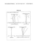
[0202] FIG. 15 is a diagram of aberration occurring at the wide angle edge of the refractive, variable magnification optical system according to the fourth example. FIG. 16 is a diagram of aberration occurring at the intermediate edge of the refractive, variable magnification optical system according to the fourth example. FIG. 17 is a diagram of aberration occurring at the telephoto edge of the refractive, variable magnification optical system according to the fourth example. In the diagrams, d indicates chromatic aberration corresponding to the d-line (λ=588 nm), g indicates chromatic aberration corresponding to the g-line (λ=436 nm), F indicates chromatic aberration corresponding to the F-line (λ=486 nm), C indicates chromatic aberration corresponding to the C-line (λ=656 nm), and e indicates chromatic aberration corresponding to the e-line (λ=546 nm). Reference numerals S and M in a field of curvature diagram indicate aberration for the sagittal plane and the meridonal plane, respectively.
[0203] Among the values for each of the examples above, r1, r2, . . . indicate radii of curvature for each lens, diaphragm surface, etc.; d1, d2, . . . indicate the thickness of the lenses, diaphragm, etc. or the distance between surfaces thereof; nd1, nd2, . . . indicate the refraction index of each lens with respect to the d-line; and νd1, νd2, . . . indicate the Abbe number with respect to the d-line of each lens.
[0204] Each aspheric surface shape above is expressed by equation [1], where the orientation of optical axis is parallel to the x axis, y is a height from the optical axis, and the traveling direction of light is assumed positive.
X = y 2 / R 1 + 1 - ( y 2 / R 2 ) + Ay 2 + By 3 + Cy 4 + Dy 6 + Ey 8 + Fy 10 + Gy 12 + Hy 14 + Iy 16 [ 1 ] ##EQU00001##
[0205] Where, R is the paraxial radius of curvature, ε is the constant of the cone, A, B, C, D, E, F, G, H, and I are aspheric coefficients of the second plane, the third plane, the fourth plane, the sixth plane, the eighth plane, the tenth plane, the twelfth plane, the fourteenth plane, and the sixteen plane, respectively.
[0206] As described, since the refractive, variable magnification optical system according to each example has the characteristics described, each is a refractive, variable magnification optical system that is thin, compact and has high optical performance at a wide-angle view.
[0207] In other words, by disposing the negative meniscus lens (that has a convex surface facing toward the object) nearest the object, among the lenses of the first lens group, the occurrence of various types of aberration including distortion can be suppressed. Further, by disposing the prism (which refracts the optical path), the plano-convex lens, and the biconvex lens subsequent to the meniscus lens, and by cementing the light transmitting surface of the prism and the plano-convex lens to configure the first lens group, the dimension of depth (thickness) of the optical system can be reduced and ghosting consequent to reflected light at a lower aspect of the prism can be suppressed. Further, by disposing the meniscus lens (that has a concave surface facing toward the image) nearest the image, among the lenses of the fourth lens group, coma of the meniscus lens (which is in the opposite direction of the coma of the meniscus lens of the first lens group) can be used to cancel out the coma of the meniscus lens of the first lens group.
[0208] In particular, by satisfying each of the conditional expressions above, the refractive, variable magnification optical system can further improve imaging performance. Forming each of the lenses in the first lens group of a glass material facilitates further reduction of the dimension of depth (thickness) of the optical system. Further, forming each of the lenses of the third and the fourth lens groups, which are susceptible to the effects of heat, of a glass material, displacement of the image plane consequent to thermal expansion of the lenses can be prevented. Lenses that are not disposed at positions susceptible to the effects of heat may be made of a resin material. By including resin lenses, manufacturing cost can be reduced.
[0209] As necessary, the refractive, variable magnification optical system is includes lenses having an aspheric surface, enabling various types of aberration to be corrected by fewer lenses as well as reductions in the size, weight, and manufacturing cost of the optical system.
[0210] As described, the refractive, variable magnification optical system according to the present invention is applicable to compact imaging apparatuses such as portable information terminals and is particularly, suitable when high optical performance is demanded.
[0211] According to the present invention, a refractive, variable magnification optical system that is not susceptible to temperature changes, is thin and compact, and has high optical performance at wide-angle views, can be provided.
[0212] Although the invention has been described with respect to a specific embodiment for a complete and clear disclosure, the appended claims are not to be thus limited but are to be construed as embodying all modifications and alternative constructions that may occur to one skilled in the art which fairly fall within the basic teaching herein set forth.
[0213] The present document incorporates by reference the entire contents of Japanese priority document, 2011-001927 filed in Japan on Jan. 7, 2011.
User Contributions:
Comment about this patent or add new information about this topic:
Images included with this patent application:
 |  |
 |  |
 |  |
 |  |
 |  |
 |  |
 |  |
 |  |
 |  |
 |  |
 |  |
| Similar patent applications: | |
| Date | Title |
|---|---|
| 2012-05-17 | Diffractive optical element and image pickup optical system |
| 2010-05-06 | Variable magnification optics with spray cooling |
| 2012-03-15 | Large-field unit-magnification catadioptric projection system |
| 2009-09-10 | Reflex, magnifying optical system |
| 2011-10-06 | Direct derivative feedforward vibration compensation system |
| New patent applications in this class: | |
| Date | Title |
|---|---|
| 2018-01-25 | Zoom lens and image pickup apparatus having the same |
| 2016-07-14 | Zoom lens system, imaging device and camera |
| 2016-07-14 | Zoom lens and camera device incorporating the same |
| 2016-07-14 | Zoom lens barrel and optical apparatus using the same |
| 2016-06-23 | Lens system, interchangeable lens apparatus, and camera system |
| New patent applications from these inventors: | |
| Date | Title |
|---|---|
| 2011-07-07 | Imaging lens, camera module, and imaging apparatus |
| Top Inventors for class "Optical: systems and elements" | |
| Rank | Inventor's name |
|---|---|
| 1 | Tsung Han Tsai |
| 2 | Hsin Hsuan Huang |
| 3 | Michio Cho |
| 4 | Niall R. Lynam |
| 5 | Tsung-Han Tsai |