Patent application title: ENCLOSURE OF ELECTRONIC DEVICE
Inventors:
Xian-Xiu Tang (Shenzhen City, CN)
Zhen-Xing Ye (Shenzhen City, CN)
Assignees:
HON HAI PRECISION INDUSTRY CO., LTD.
HONG FU JIN PRECISION INDUSTRY (ShenZhen) CO., LTD.
IPC8 Class: AH05K720FI
USPC Class:
174547
Class name: Boxes and housings with electrical device cooled
Publication date: 2012-05-24
Patent application number: 20120125681
Abstract:
An enclosure of an electronic device includes a chassis, a sliding plate
slidably disposed on the chassis, and a pivot member. A number of vent
holes and a location hole are defined in the chassis. A number of teeth
are formed on a sidewall bounding the location hole. A through slot is
defined in the sliding plate. A toothed rack is formed on a sidewall
bounding the through slot. The pivot member extends through the through
slot and the location hole. The pivot member includes a toothed portion
engaging with the toothed rack and the teeth, and a smooth neck. When the
toothed portion disengages from the teeth, the neck is pivotably received
in the location hole, the pivot member is pivoted to drive the sliding
member to slide relative to the chassis by the toothed portion rolling on
the toothed rack, thereby exposing or covering the vent holes.Claims:
1. An enclosure of an electronic device, the enclosure comprising: a
chassis defining a plurality of first vent holes and a location hole, a
plurality of teeth formed on a sidewall bounding the location hole; a
sliding plate slidably disposed on the chassis, the sliding plate
defining a through slot, a toothed rack extending from a sidewall
bounding the through slot, the toothed rack extending along a sliding
direction of the sliding plate; and a pivot member extending through the
through slot and the location hole, the pivot member comprising a toothed
portion engaging with the toothed rack and the teeth of the location
hole, and a smooth neck extending from the toothed portion; wherein when
the toothed portion disengages from the teeth, the neck is pivotally
received in the location hole, the pivot member is pivoted to drive the
sliding member to slide relative to the chassis by the toothed portion
rolling on the toothed rack, thereby exposing or covering the plurality
of first vent holes.
2. The enclosure of claim 1, wherein the pivot member further comprises a head and a block respectively resisting against the sliding member and the chassis; the head is attached to the toothed portion opposite to the neck, and the block is detachably mounted to the neck.
3. The enclosure of claim 2, wherein the block is ring-shaped and fits about the neck, a diameter of the neck is less than an outer diameter of the toothed portion, and less than a diameter of the block.
4. The enclosure of claim 1, wherein two parallel rows of clips protrude from the chassis and respectively slidably clamp opposite sides of the sliding member.
5. The enclosure of claim 1, wherein a plurality of second vent holes is defined in the sliding member, corresponding to the plurality of first vent holes of the chassis.
6. An enclosure of an electronic device, the enclosure comprising: a chassis defining a plurality of first vent holes; a sliding plate slidably disposed on the chassis, the sliding plate defining a through slot, a toothed rack extending from a sidewall bounding the through slot, the toothed rack extending along a sliding direction of the sliding plate; and a pivot member comprising a toothed portion extending through the through slot and meshing with the toothed rack, and a neck extending from the toothed portion to pivotably engage with the chassis; wherein when the pivot member is pivoted, with the toothed portion meshing with the toothed rack, the sliding plate is driven to slide, thereby covering, uncovering, or partially covering the plurality of first vent holes of the chassis.
7. The enclosure of claim 6, wherein the sliding plate defines a plurality of second vent holes, corresponding to the plurality of first vent holes of the chassis.
Description:
BACKGROUND
[0001] 1. Technical Field
[0002] The present disclosure relates to an enclosure of an electronic device.
[0003] 2. Description of Related Art
[0004] Often, there are several heat-generating components enclosed by an enclosure of an electronic device. Nowadays, there is a desire for adjusting airflow flowing into the enclosure according to how much heat is being generated by the heat-generating components.
BRIEF DESCRIPTION OF THE DRAWINGS
[0005] Many aspects of the embodiments can be better understood with reference to the following drawings. The components in the drawings are not necessarily drawn to scale, the emphasis instead being placed upon clearly illustrating the principles of the embodiments. Moreover, in the drawings, like reference numerals designate corresponding parts throughout the several views.
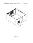
[0006] FIG. 1 is an assembled, isometric view of an exemplary embodiment of an enclosure of an electronic device, the enclosure includes a chassis, a sliding plate, and a pivot member.
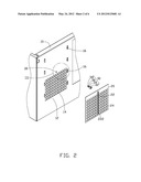
[0007] FIG. 2 is an exploded, isometric view of the enclosure of FIG. 1, showing only partial structure of the chassis.
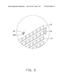
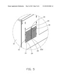
[0008] FIG. 3 is an enlarged, isometric view of an encircled portion III of FIG. 2.
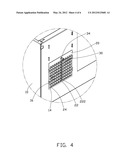
[0009] FIG. 4 is an enlarged, isometric view of an encircled portion IV of FIG. 1.
[0010] FIG. 5 shows a first use state of FIG. 4.
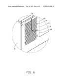
[0011] FIG. 6 shows a second use state of FIG. 4.
DETAILED DESCRIPTION
[0012] The present disclosure, including the accompanying drawings, is illustrated by way of examples and not by way of limitation. It should be noted that references to "an" or "one" embodiment in this disclosure are not necessarily to the same embodiment, and such references mean at least one.
[0013] Referring to FIG. 1, an enclosure in accordance with an exemplary embodiment includes a chassis 10, a sliding plate 20, and a pivot member 30.
[0014] Referring to FIGS. 2 and 3, the chassis 10 includes a rectangular vent region 12. A plurality of arrayed vent holes 14 is defined in the vent region 12. Two parallel rows of clips 16 protrude from the chassis 10, respectively at opposite sides of the vent region 12. A circular location hole 18 is defined in the chassis 10 between the rows of clips 16. A plurality of teeth 182 is formed on a sidewall bounding the location hole 18.
[0015] The sliding plate 20 is slidably mounted between the rows of clips 16. A longitudinal through slot 22 is defined in a center of the sliding plate 20. A plurality of arrayed vent holes 24 is defined in the sliding plate 20, corresponding to the vent holes 14 of the chassis 10. A longitudinal toothed rack 222 extends from a long sidewall bounding the through slot 22.
[0016] The pivot member 30 includes a head 32, a toothed portion 34 extending from the head 32, a smooth neck 36 extending from the toothed portion 34 away from the head 32, and a ring-shaped block 38 detachably mounted to the neck 36. A diameter of the neck 36 is less than an outer diameter of the toothed portion 34, and less than a diameter of the block 38, thereby allowing the neck 36 to extend through the location hole 18 of the chassis 10 and allowing the toothed portion 34 to engage with the teeth 182.
[0017] Referring to FIGS. 1 to 4, in assembly, the sliding plate 20 is slidably disposed on the chassis 10, with the rows of clips 16 of the chassis 10 respectively clamping opposite sides of the sliding plate 20. The toothed rack 222 extends along a sliding direction of the sliding plate 20. When the through slot 22 of the sliding plate 20 is in alignment with the location hole 18 of the chassis 10, the pivot member 30, without the block 38, extends through the through slot 22 and the location hole 18, with the toothed portion 34 engaging with the toothed rack 222 and the teeth 182. The block 38 fixedly fits about the neck 36. Thus, the pivot member 30 is mounted to the chassis 10, with the head 32 and the block 38 respectively resisting against the sliding plate 20 and the chassis 10.
[0018] Referring to FIGS. 5 and 6, to adjust airflow flowing into the chassis 10, the pivot member 30 is drawn outward. The toothed portion 34 disengages from the teeth 182 and escapes from the location hole 18, while the neck 36 extends into the location hole 18. The pivot member 30 is pivoted by operating the head 32, the toothed portion 34 rolls on the toothed rack 222, thereby driving the sliding plate 20 to slide relative to the chassis 10 along the rows of clips 16. The vent holes 24 of the sliding plate 20 can be set in alignment with or in partial alignment with the vent holes 14 of the chassis 10, thereby adjusting airflow flowing into the chassis 10. The pivot member 30 is moved inward to allow the toothed portion 34 to engage with the teeth 182 again, thereby the sliding plate 20 is held in place.
[0019] In other embodiments, the sliding plate 20 does not define any vent hole 24.
[0020] When the sliding plate 20 slides relative to the chassis 10, the sliding plate 20 exposes or covers the vent holes 14 of the chassis 10, thereby adjusting airflow flowing into the chassis 10.
[0021] It is to be understood, however, that even though numerous characteristics and advantages have been set forth in the foregoing description of embodiments, together with details of the structures and functions of the embodiments, the present disclosure is illustrative only and changes may be made in detail, especially in matters of shape, size, and arrangement of parts within the principles of the present disclosure to the full extent indicated by the broad general meaning of the terms in which the appended claims are expressed.
User Contributions:
Comment about this patent or add new information about this topic:
Images included with this patent application:
 |  |
 |  |
 |  |
 |
| Similar patent applications: | |
| Date | Title |
|---|---|
| 2013-10-17 | Soldering device, soldering method, and substrate and electronic component produced by the soldering device or the soldering method |
| 2012-01-19 | Shell of electronic device |
| 2013-09-19 | Case for electronic device |
| 2013-10-17 | Cable positioning mechanism and electronic device using the same |
| 2011-11-24 | Casing of electronic device |
| New patent applications in this class: | |
| Date | Title |
|---|---|
| 2022-05-05 | Electrical component housing with cooling channels |
| 2016-12-29 | Current carrying systems and methods of assembling the same |
| 2016-03-24 | Electrical housing having cooling and sound-absorbing means |
| 2015-11-05 | Conduction cooled module |
| 2015-10-29 | Plug module holder |
| New patent applications from these inventors: | |
| Date | Title |
|---|---|
| 2014-03-20 | Computer enclosure and fan mounting apparatus |
| 2013-12-05 | Water tank for water-cooling heat dissipation system |
| 2013-09-26 | Server cabinet |
| 2013-09-12 | Server cabinet |
| 2013-06-27 | Cabinet with cooling system |
| Top Inventors for class "Electricity: conductors and insulators" | |
| Rank | Inventor's name |
|---|---|
| 1 | Douglas B. Gundel |
| 2 | Shou-Kuo Hsu |
| 3 | Michimasa Takahashi |
| 4 | Hideyuki Kikuchi |
| 5 | Tsung-Yuan Chen |