Patent application title: DEDUSTING APPARATUS AND CONTAINER DATA CENTER INCLUDING THE SAME
Inventors:
Yao-Ting Chang (Tu-Cheng, TW)
Yao-Ting Chang (Tu-Cheng, TW)
Assignees:
HON HAI PRECISION INDUSTRY CO., LTD.
IPC8 Class: AB65D8500FI
USPC Class:
206320
Class name: Special receptacle or package for a household appliance
Publication date: 2012-05-10
Patent application number: 20120111749
Abstract:
A dedusting apparatus is for a container data center. The container data
center includes a mobile container and a number of servers mounted inside
the container. The dedusting apparatus includes a sensor, an air shower,
a timer, and a controller. The sensor is mounted at an entrance of the
container to output a first sensed signal when a user enters the
container through the entrance. The timer starts timing according to the
first sensed signal. When the timer reaches a preset time, the timer
outputs a time signal. The controller activates the air shower according
to the first sensed signal and deactivates the air shower according to
the time signal.Claims:
1. A dedusting apparatus mounted in a container data center, the
container data center comprising a mobile container and a plurality of
servers accommodated in the container, the dedusting apparatus
comprising: a sensor mounted at an entrance of the container, wherein
when a user enters the container through the entrance, the sensor outputs
a first sensed signal; an air shower mounted at the entrance of the
container; a timer to start to time according to the first sensed signal,
wherein when the timer reaches a preset time, the timer outputs a time
signal; and a controller to activate the air shower according to the
first sensed signal and deactivate the air shower according to the time
signal.
2. The dedusting apparatus of claim 1, wherein the sensor is a gas pressure sensor.
3. The dedusting apparatus of claim 1, wherein the sensor is an infrared sensor.
4. The dedusting apparatus of claim 1, wherein the sensor is a microwave sensor.
5. A container data center comprising: a mobile container; a plurality of servers accommodated in the container; and a dedusting apparatus comprising: a sensor mounted at an entrance of the container, wherein when a user enters the container through the entrance, the sensor outputs a first sensed signal; an air shower mounted at the entrance of the container; a timer to start to time according to the first sensed signal, wherein when the timer reaches a preset time, the timer outputs a time signal; and a controller to activate the air shower according to the first sensed signal and deactivate the air shower according to the time signal.
6. The container data center of claim 5, wherein the sensor is a gas pressure sensor.
7. The container data center of claim 5, wherein the sensor is an infrared sensor.
8. The container data center of claim 5, wherein the sensor is a microwave sensor.
9. A dedusting apparatus mounted in a container data center, the container data center comprising a mobile container and a plurality of servers accommodated in the container, the dedusting apparatus comprising: a sensor mounted at an entrance of the container, wherein when a user enters the container through the entrance, the sensor outputs a first sensed signal, when the user leaves the container through the entrance, the sensor outputs a second sensed signal; an air shower mounted at the entrance of the container; and a controller to activate the air shower according to the first sensed signal and deactivate the air shower according to the second sensed signal.
10. The dedusting apparatus of claim 9, wherein the sensor is a gas pressure sensor.
11. The dedusting apparatus of claim 9, wherein the sensor is an infrared sensor.
12. The dedusting apparatus of claim 9, wherein the sensor is a microwave sensor.
Description:
BACKGROUND
[0001] 1. Technical Field
[0002] The present disclosure relates to a dedusting apparatus and a container data center including the dedusting apparatus.
[0003] 2. Description of Related Art
[0004] Container data centers are located outdoors. As a result, dust may easily get into the container data centers.
BRIEF DESCRIPTION OF THE DRAWINGS
[0005] Many aspects of the present embodiments can be better understood with reference to the following drawing. The components in the drawing are not necessarily drawn to scale, the emphasis instead being placed upon clearly illustrating the principles of the present embodiments. Moreover, in the drawing, all the views are schematic, and like reference numerals designate corresponding parts throughout.
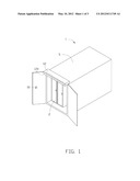
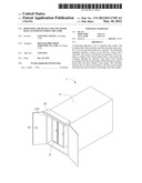
[0006] FIG. 1 is a schematic diagram of an exemplary embodiment of a container data center.
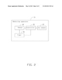
[0007] FIG. 2 is a block diagram of an exemplary embodiment of a dedusting apparatus of the container data center of FIG. 1.
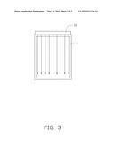
[0008] FIG. 3 is a schematic diagram of the dedusting apparatus of FIG. 2.
DETAILED DESCRIPTION
[0009] The disclosure, including the accompanying drawings, is illustrated by way of examples and not by way of limitation. It should be noted that references to "an" or "one" embodiment in this disclosure are not necessarily to the same embodiment, and such references mean at least one.
[0010] Referring to FIGS. 1 and 2, an exemplary embodiment of a container data center 1 includes a mobile container 5, a plurality of servers 2 accommodated in the container 5, and a dedusting apparatus 3 mounted in the container 5.
[0011] The dedusting apparatus 3 includes a sensor 10, an air shower 12, a controller 15, and a timer 16.
[0012] The sensor 10 and the air shower 12 are mounted at an entrance of the container 5. When a user enters the container 5, the sensor 10 outputs a sensed signal to the controller 15 and the timer 16. The controller 15 activates the air shower 12 to clear dust attached on clothes or hairs of the user. The timer 16 starts to time according to the sensed signal.
[0013] In this embodiment, the sensor 10 is a gas pressure sensor. When the user enters the container 5, atmospheric pressure at the entrance of the container 5 changes. As a result, the gas pressure sensor outputs the sensed signal to the controller 15 and the timer 16. In other embodiments, other sensors may replace the gas pressure sensor, such as an infrared sensor or a microwave sensor.
[0014] When the timer 16 reaches a preset time, such as ten seconds, the timer 16 stops timing and outputs a time signal to the controller 15. The controller 15 deactivates the air shower 12.
[0015] Referring to FIG. 1 again, the air shower 12 includes a plurality of air outlets 120 connected to an air can through pipes (not shown). When the controller 15 receives the sensed signal from the sensor 10, the controller 15 connects the air outlets 120 with the air can. As a result, air flow from the air shower 12 clears dust attached on clothes or hairs of the user, as shown in FIG. 3.
[0016] When the user leaves the container 5, the sensor 10 outputs the sensed signal to the controller 15 and the timer 16 again. The controller 15 activates the air shower 12. The timer 16 starts to time. When the timer 16 reaches the preset time, the timer 16 stops timing and outputs the time signal to the controller 15. The controller 15 deactivates the air shower 12.
[0017] In other embodiments, the timer 16 can be omitted. In other words, when the user enters the container 5, the sensor 10 outputs a first sensed signal to the controller 15. The controller 15 activates the air shower 12. Before the user leaves the container 5, the air shower 12 is functional at all times, avoiding cold air in the container 5 from leaking out. When the user leaves the container 5, the sensor 10 outputs a second sensed signal to the controller 15. The controller 15 deactivates the air shower 12.
[0018] The foregoing description of the exemplary embodiments of the disclosure has been presented only for the purposes of illustration and description and is not intended to be exhaustive or to limit the disclosure to the precise forms disclosed. Many modifications and variations are possible in light of the above everything. The embodiments were chosen and described in order to explain the principles of the disclosure and their practical application so as to enable others of ordinary skill in the art to utilize the disclosure and various embodiments and with various modifications as are suited to the particular use contemplated. Alternative embodiments will become apparent to those of ordinary skills in the art to which the present disclosure pertains without departing from its spirit and scope. Accordingly, the scope of the present disclosure is defined by the appended claims rather than the foregoing description and the exemplary embodiments described therein.
User Contributions:
Comment about this patent or add new information about this topic:
Images included with this patent application:
 |  |
 |  |
| Similar patent applications: | |
| Date | Title |
|---|---|
| 2012-12-20 | Storage container system including universal lids |
| 2012-10-04 | Tablet bay and bag incorporating the same |
| 2012-12-20 | Polymeric reagents comprising a terminal vinylic group and conjugates formed therefrom |
| 2010-11-11 | Apparatus for shielding h-field signals |
| 2011-05-26 | Device housing and method for making the same |
| New patent applications in this class: | |
| Date | Title |
|---|---|
| 2016-06-16 | Protective cases |
| 2016-05-19 | Encasement |
| 2016-01-21 | Packing box for electric home appliance |
| 2015-11-26 | Tub insert system for top loading washer |
| 2015-10-29 | Case for remote control units |
| New patent applications from these inventors: | |
| Date | Title |
|---|---|
| 2014-03-06 | Electronic device with heat dissipation assembly |
| 2013-10-03 | Fan |
| 2013-09-26 | Container with cooling system |
| 2013-09-19 | Container with cooling system |
| 2013-09-12 | Container module with cooling system |
| Top Inventors for class "Special receptacle or package" | |
| Rank | Inventor's name |
|---|---|
| 1 | Donald E. Weder |
| 2 | Brett R. Glass |
| 3 | Daniel Lee Bizzell |
| 4 | Andrea Biondi |
| 5 | Nicole E. Glass |