Patent application title: METHOD AND APPARATUS FOR AN ELECTRICALLY COOLED PITCHER
Inventors:
John O. Dellamorte, Jr. (Sandwich, MA, US)
James T. Dellamorte (Sandwich, MA, US)
IPC8 Class: AF25B2102FI
USPC Class:
62 362
Class name: Thermoelectric; e.g., peltier effect interior of enclosure cooled; e.g., refrigerator portable, having transporting feature; e.g., handle
Publication date: 2012-04-19
Patent application number: 20120090333
Abstract:
Embodiments of the present invention relate to an apparatus that includes
a thermoelectric cooling unit coupled to a power supply and a removable
container configured for holding and dispensing a liquid. The
thermoelectric cooling unit includes a heat sink and a thermoelectric
cooling plate. The thermoelectric cooling plate includes first and second
surfaces spaced apart from each other. The first surface expends thermal
energy from the second surface to the heat sink. The container holds and
dispenses a liquid. The container includes a thermally conductive portion
that is removably positioned on the thermoelectric cooling unit by having
frictional contact with the second surface of the thermoelectric cooling
plate. The frictional contact is sufficient to result in transfer of
thermal energy from the conductive portion of the container on to the
second surface of the thermoelectric cooling plate and effectively cool
the liquid in the container.Claims:
1. An apparatus comprising: a thermoelectric cooling unit coupled to a
power supply, the thermoelectric cooling unit including a heat sink and a
thermoelectric cooling plate, the thermoelectric cooling plate having
first and second surfaces spaced apart from each other, the first surface
arranged to expend thermal energy from the second surface to the heat
sink; and a removable container configured for holding and dispensing a
liquid, the container including a thermally conductive portion removably
positioned on the thermoelectric cooling unit by having frictional
contact with the second surface of the thermoelectric cooling plate, the
frictional contact being sufficient to result in transfer of thermal
energy from the conductive portion of the container on to the second
surface of the thermoelectric cooling plate and effectively cool the
liquid in the container.
2. The apparatus of claim 1 wherein the liquid is filtered water.
3. The apparatus of claim 1 wherein the container is a water pitcher.
4. The apparatus of claim 1 wherein volume of the container is at least two times larger than volume of a typical drinking cup.
5. The apparatus of claim 1 wherein the transfer of thermal energy from the conductive portion of the container on to the second surface of the thermoelectric cooling plate is arranged to cool the liquid over a period of time.
6. The apparatus of claim 1 further including a controller unit, the controller unit detecting whether the container is no longer in contact with the thermoelectric cooling unit and reducing power to the thermoelectric cooling unit in an event the container is no longer in contact with the thermoelectric cooling unit.
7. The apparatus of claim 6 wherein the controller is arranged to reduce the power to the thermoelectric cooling unit after a predetermined period of time has lapsed.
8. The apparatus of claim 1 wherein the conductive portion is on a base of the container.
9. The apparatus of claim 1 wherein the conductive portion is on a side or top of the container.
10. The apparatus of claim 1 wherein the container is insulated to preserve temperature of the liquid.
11. An apparatus comprising: a water purification filter coupled to a water source, the water purification filter producing filtered water suitable for drinking; a thermoelectric cooling unit coupled to a power supply, the thermoelectric cooling unit including a heat sink and a thermoelectric cooling plate, the thermoelectric cooling plate having first and second surfaces spaced apart from each other, the first surface arranged to expend thermal energy from the second surface to the heat sink; and a container configured for holding and dispensing the filtered water; the container being in fluid communication with the filtered water produced by the water purification filter and including a thermally conductive portion removably positioned on the thermoelectric cooling unit by having frictional contact with the second surface of the thermoelectric cooling plate, the frictional contact being sufficient to result in transfer of thermal energy from the conductive portion of the container on to the second surface of the thermoelectric cooling plate and effectively cool the filtered water in the container.
12. An apparatus comprising: a thermoelectric cooling unit coupled to a power supply, the thermoelectric cooling unit including a heat sink and a thermoelectric cooling plate, the thermoelectric cooling plate having first and second surfaces spaced apart from each other, the first surface arranged to expend thermal energy from the second surface to the heat sink; a water purification filter coupled to a water source and the power supply, the water purification filter using power supplied by the power supply to produce filtered water suitable for drinking; a container configured for holding and dispensing the filtered water; the container being in fluid communication with the filtered water and including a thermally conductive portion removably positioned on the thermoelectric cooling unit by having frictional contact with the second surface of the thermoelectric cooling plate, the frictional contact being sufficient to result in transfer of thermal energy from the conductive portion of the container on to the second surface of the thermoelectric cooling plate and effectively cool the filtered water in the container.
13. A method for cooling a fluid comprising: removably coupling a container configured for holding and dispensing the liquid to a thermoelectric cooling unit, the container having a conductive portion, the thermoelectric cooling unit including a heat sink and a thermoelectric cooling plate, the thermoelectric cooling plate having first and second surfaces spaced apart from each other, the first surface arranged to expend thermal energy from the second surface to the heat sink; and cooling the fluid as a function of being transfer of thermal energy from the conductive portion of the container on to the second surface of the thermoelectric cooling plate.
14. The method of claim 13 wherein the liquid is filtered water.
15. The method of claim 13 wherein the container is a water pitcher.
16. The method of claim 13 wherein volume of the container is at least two times larger than volume of a typical drinking cup.
17. The method of claim 13 further including cooling the liquid over a period of time as a function of the transfer of thermal energy from the conductive portion of the container on to the second surface of the thermoelectric cooling plate.
18. The method of claim 13 further including detecting whether the container is no longer in contact with the thermoelectric cooling unit and reducing power to the thermoelectric cooling unit in an event the container is no longer in contact with the thermoelectric cooling unit.
19. The method of claim 18 further including reducing the power to the thermoelectric cooling unit after a predetermined period of time has lapsed.
20. The method of claim 18 further including reducing the power to the thermoelectric cooling unit after a predetermined temperature has been achieved.
21. The method of claim 13 wherein the conductive portion is on a base of the container.
22. The method of claim 13 wherein the conductive portion is on a side of the container.
23. The method of claim 13 further including insulating the container to preserve temperature of the liquid.
Description:
RELATED APPLICATION
[0001] This application claims the benefit of U.S. Provisional Application No. 61/347,727, filed on May 24, 2010. The entire teachings of the above application are incorporated herein by reference.
BACKGROUND
[0002] Thermoelectric cooling relates to employing a heat flux between junctions of materials to transfer heat from one side of a device to another side of the device using electrical energy. Thermoelectric cooling units often have low efficiency when compared against traditional cooling devices (e.g., electric refrigerators).
SUMMARY
[0003] A method and corresponding apparatus in an example embodiment of the present invention relates to a thermoelectric cooling unit and a container for holding and dispensing a liquid. The thermoelectric cooling unit is coupled to a power supply and includes a heat sink and a thermoelectric cooling module (plate). The thermoelectric cooling module includes first and second surfaces that are spaced apart from each other. The first surface of the cooling plate module is arranged to expend thermal energy from the second surface of the cooling plate to the heat sink. The container includes a thermally conductive portion that is removably positioned on the thermoelectric cooling unit. The container has frictional contact with the second surface of the thermoelectric cooling plate. The frictional contact is sufficient to result in transfer of thermal energy from the conductive portion of the container on to the second surface of the thermoelectric cooling plate and effectively cool the liquid in the container.
[0004] The liquid may be filtered water.
[0005] Another example embodiment of the present invention relates to a method and a corresponding apparatus that includes a water purification filter, a thermoelectric cooling unit, and a container for holding and dispensing water. The water purification filter is coupled to a water source to produce filtered water suitable for drinking. The thermoelectric cooling unit is coupled to a power supply and includes a heat sink and a thermoelectric cooling plate. The thermoelectric cooling plate includes first and second surfaces that are spaced apart from each other. The first surface of the thermoelectric cooling plate is arranged to expend thermal energy from the second surface to the heat sink. The container is configured for holding and dispensing the filtered water and is in fluid communication with the filtered water produced by the water purification filter. The container includes a thermally conductive portion that is removably positioned on the thermoelectric cooling unit by having frictional contact with the second surface of the thermoelectric cooling plate. The frictional contact is sufficient to result in transfer of thermal energy from the conductive portion of the container on to the second surface of the thermoelectric cooling plate and effectively cool the filtered water in the container.
[0006] Yet another example embodiment of the present invention relates to a method and corresponding apparatus that includes a thermoelectric cooling unit, a water purification filter, and a container configured for holding and dispensing the filtered water. The thermoelectric cooling unit is coupled to a power supply. The thermoelectric cooling unit includes a heat sink and a thermoelectric cooling plate. The thermoelectric cooling plate includes first and second surfaces that are spaced apart from each other. The first surface is arranged to expend thermal energy from the second surface to the heat sink. The water purification filter is coupled to a water source and the power supply. The water purification filter uses power supplied by the power supply to produce filtered water suitable for drinking. The container is configured for holding and dispensing the filtered water. The container is in fluid communication with the filtered water and includes a thermally conductive portion removably positioned on the thermoelectric cooling unit by having frictional contact with the second surface of the thermoelectric cooling plate. The frictional contact is sufficient to result in transfer of thermal energy from the conductive portion of the container on to the second surface of the thermoelectric cooling plate and effectively cool the filtered water in the container.
[0007] The container may be a water pitcher, for example. The volume of the container may be at least two times larger than volume of a typical drinking cup.
[0008] The transfer of thermal energy from the conductive portion of the container on to the second surface of the thermoelectric cooling plate may cool the liquid over a period of time.
[0009] The example embodiments may further include a controller unit that detects whether the container is no longer in contact with the thermoelectric cooling unit and reduces power to the thermoelectric cooling unit in an event the container is no longer in contact with the thermoelectric cooling unit. The controller may be arranged to reduce the power to the thermoelectric cooling unit after a predetermined period of time has lapsed or a predetermined temperature of the container or its contents is achieved.
[0010] The conductive portion may be on a base or a side of the container. The container may be insulated to preserve temperature of the liquid.
BRIEF DESCRIPTION OF THE DRAWINGS
[0011] The foregoing will be apparent from the following more particular description of example embodiments of the invention, as illustrated in the accompanying drawings in which like reference characters refer to the same parts throughout the different views. The drawings are not necessarily to scale, emphasis instead being placed upon illustrating embodiments of the present invention.
[0012] FIG. 1 is a schematic view of an example embodiment of the present invention.
[0013] FIG. 2 is a high-level illustration of a top view of an example embodiment of the present invention.
[0014] FIG. 3 is a block diagram of a control device that may be employed with example embodiments of the present invention.
[0015] FIG. 4 is a schematic view of another example embodiment of the present invention.
[0016] FIG. 5A is an example embodiment of the present invention that includes a water purification filter.
[0017] FIG. 5B is an example embodiment of the present invention that includes a water purification filter included in a liquid container.
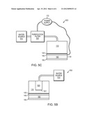
[0018] FIG. 5c is an example embodiment of the present invention that includes a water purification filter coupled with a power source.
DETAILED DESCRIPTION
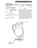
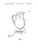
[0019] FIG. 1 is a schematic illustration of an example embodiment 100 of the present invention. A thermoelectric cooling device may be used to electrically cool a pitcher to keep a beverage (or pitcher contents) cool without needing to sacrifice refrigerator space. The term "pitcher" is used herein to refer to any container that can be used for holding and/or dispending a liquid. The example embodiment 100 includes a pitcher 110 that has a conductive portion 120. The conductive portion 120 may be on the sides, top, base, or any other portion of the pitcher 110. For example, in the embodiment 100 shown in FIG. 1, the conductive portion 120 is in the base of the pitcher. The conductive base 120 (i.e., conductive portion 120) is removably positioned on a thermoelectric cooling unit 130.
[0020] In certain embodiments, the thermoelectric cooling unit 130 may be included in a docking or a mounting station 135 on which the pitcher is removably mounted. The thermoelectric cooling unit 130 includes a first surface 140 and a second surface 150. The first 140 and second 150 surfaces may be positioned at a predetermined spacing from one another. The first surface 150 is configured to expend thermal energy from the second surface 140 to a heat sink 160 included in the thermoelectric cooling unit 130. Therefore, the second surface 140 is, temperature wise, cooler than the first surface 150. This cool surface 140 of the thermoelectric cooling unit 130 is the surface upon which the conductive base 120 of the pitcher 110 is removably mounted.
[0021] The thermoelectric cooling unit 130 and the mounting/docking station 135 may include a power supply 170 that provides electric power to the thermoelectric cooling unit 130 and the heat sink 160. In certain embodiments, the mounting/docking station 135 may contain the power supply for the thermoelectric cooling unit 130. This allows the device to be powered from a standard AC outlet.
[0022] In certain embodiments contact between the pitcher 110 and the docking station 135 may be due to frictional contact. Accordingly, one may remove the pitcher from the docking station 135 easily. The frictional contact allows for the thermal energy from the thermoelectric cooling unit 130 to be transmitted efficiently to the conductive base 120 of the pitcher 110. In certain embodiments, the conductive base 120 of the pitcher 110 may include fins (not shown) that partially extend into the liquid (or other pitcher contents) to facilitate efficient cooling transmission of a liquid 180 in the pitcher.
[0023] The liquid 180 in the pitcher 110 may be water, lemonade, soda, or any other form of drinking beverage. The pitcher 110 maintains the liquid 180 at a temperature colder than room temperature without requiring refrigeration space. The thermoelectric cooling device 130 and the pitcher 110 may be positioned outside of a refrigeration unit (e.g., on a kitchen counter) to maintain the liquid 180 at a cooled temperature at all times without using refrigeration space. In some embodiments, the thermoelectric cooling device 130 and the pitcher 110 may be mountable from the top to dock under surfaces, for example, under a kitchen counter.
[0024] The pitcher 110 may have insulating properties to assist in preserving the cool temperature of the liquid 180 container inside. Insulating the pitcher 110 also helps with increasing the efficiency of the cooling process.
[0025] In certain embodiments, the pitcher 110 capacity is multiple servings. For example, greater than two servings. In certain embodiments, the volume of the pitcher 110 is at least two times greater than the volume of a typical drinking cup.
[0026] Given that the pitcher 110 is maintained on the docking station 135 using frictional contact, the pitcher 110 can be easily removed from the docking station 135. Since the pitcher does not include any wiring, the pitcher can be easily cleaned using traditional cleaning techniques. For example, the pitcher 110 may be cleaned using soap and water or in a dishwasher.
[0027] The thermoelectric cooling unit 135 operates based on the peltier effect. The peltier effect relates to effects of an electrical current flowing at a junction of two conductor plates. When an electrical current flows through a circuit, the heat evolved at a conductive plate is absorbed at another conductive plate, resulting in transfer of heat between the conductive plates. Since peltier effect-based coolers are energy efficient, the thermoelectric cooling unit 135 consumes low energy and can be used over long periods of time to cool and maintain the liquid 180 at low temperatures.
[0028] FIG. 2 is a high-level illustration of a top 201 view of an example embodiment 200 of the present invention. As shown in the top view 201, a container wall 205 may include an insulating portion 206 used in preserving the cool temperature of the liquid 180 inside the container. The outside of the container 110 is naturally surrounded by air 209.
[0029] The example embodiment 200 utilizes convection of air 209 and liquid 180 by employing one or more chimneys 210, 220 in the air 209 and liquid 180 sides of the container wall 205. In certain embodiments, the chimneys are formed using rectangular tubes of a conductive material. For example, in some embodiments, rectangular aluminum tubes may be used to implement the chimneys. In operation, as heat is transferred from the air side 209 of the container wall 205, 206, the chimneys 220 heat up. This heat is transferred from chimneys 220 to the surrounding air 209. Since cool air is denser than warm air, the warm air moves out of the chimneys 220 and is replaced by cool air. In certain embodiments, a powered fan (not shown) may be used to facilitate air cooling.
[0030] A thermoelectric cooling unit 130 is positioned between the chimneys 220. The thermoelectric cooling unit 130, as explained with relation to FIG. 1, includes a second surface 140, a first surface 150, and a heat sink 160. The second surface 140 is positioned against the container wall 206 and the first surface 150 is positioned under the chimneys 220. The second surface 140 has a cooler temperature than the first surface 150. The heat sink 160 is positioned under the second surface 140 such that the cool air from the chimneys 220 is drawn into the heat sink 160.
[0031] In the liquid side 180 of the container, the chimney 210 is maintained under the second surface 140 of the thermoelectric cooling unit 130 and as such has cooler temperature than the outside temperature. As the liquid 180 cools in the inside chimney 210, it drops to the bottom of the container (given that cold liquid is denser than warm liquid) and warm liquid from the top of the chimney 210 is drawn into the chimney 210 for cooling.
[0032] In some embodiments, the thermoelectric cooling unit 130 may be positioned between the chimneys 220 and a flat plate (not shown) located on the container wall 205, 206. In certain embodiments, a conductive ointment may be used to facilitate heat transfer. In certain embodiments, the chimneys 220 and the flat plate are connected to ensure that an area for heat transfer to the liquid 180 is provided. The connection between the flat plate and the container wall 205 may be separable metal-to-metal contact. In certain embodiments, the flat plat may be made to cover a large portion of the container wall 205 and provide for a large area of metal-to-metal contact. By making the metal-to-metal contact area larger, the efficiency of the cooling process may be increased.
[0033] FIG. 3 is an example of a control device 300 that may be employed with example embodiments of the present invention. The control device 300 includes a microcontroller 310 that receives an input signal 309 from a thermistor 350. The thermistor 350 measures the temperature of the liquid 180 (FIG. 1) inside the container 110 (FIG. 1) and transmits a signal regarding same to the microprocessor 310. The microcontroller 310 employs the input signal 309 to deliver required amounts of energy to the thermoelectric cooling unit. The signal 311 from the microcontroller 310 may be a high current pulse modulated signal . The microprocessor 310 may employ the duty cycle of the signal 309 to determine the required energy for the thermoelectric cooling unit. The microprocessor 310 also controls the thermoelectric cooling unit 340 to cool and maintain a constant temperature of the liquid 180 (FIG. 1) inside the container 110 (FIG. 1). The microprocessor 310 also determines if the pitcher 110 is separated from its mounting/docking station 135 and delivers a signal 311 to a switch 330 to shut down or reduce the energy delivered to the thermoelectric cooler 340. The microprocessor 310 may signal the switch 330 to shut down or reduce energy delivered to the thermoelectric cooler 340 after a predetermined period of time has passed or a predetermined temperature of the pitcher 110/pitcher contents 180 is achieved. Certain temperature sensing techniques may be employed to accomplish that and to cycle between higher and lower energy amounts as a function of threshold temperatures achieved and maintained.
[0034] The controller 300 may be coupled with a power supply 320 that supplies the controller 300 with required power.
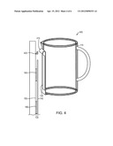
[0035] FIG. 4 is a high-level illustration of another example embodiment 400 of the present invention. In this embodiment 400, the pitcher 110 includes a conductive base located on a side of the pitcher 110. The example embodiment 400 employs a hook 410 to connect the pitcher to a pivot 420. In this embodiment 400, the thermoelectric cooling unit 130 is arranged such that once the pitcher is mounted on the pivot 420 using the hook 410, the cool plate (i.e., second plate) 140 of the thermoelectric cooling unit 130 is in contact with the pitcher. The heat sink 160 and the first plate 150 of the thermoelectric cooling unit 130 are coupled with the second plate 140 to allow for heat transfer between the conductive base 120 and the second plate 140.
[0036] The configuration shown in this example embodiment 400 may used to mount the pitcher 110 on vertical surface (e.g., on a wall, under a counter, etc.).
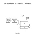
[0037] FIGS. 5A-5C illustrate example embodiments of the present invention that include a water purification filter 520. FIG. 5A demonstrates an example embodiment 500 that includes a purification filter 520 coupled to the container 110.
[0038] The example embodiment 500 includes a water purification filter 520 that is coupled to a water source 510. The water purification filter 520 may be a traditional water purification filter used in common household applications. The water purification filter 520 produces filtered water that is suitable for drinking.
[0039] A thermoelectric cooling unit 130 is coupled to a power supply 170. The thermoelectric cooling unit 130 includes a heat sink 160 and thermoelectric cooling plates 140, 150. The cooling plates 140, 150 are spaced apart from each other such that the second surface 140 is cooler in temperature than the first surface 150.
[0040] The example embodiment also includes a container 110 configured for holding and dispensing the filtered water. The container 110 is in fluid communication with the filtered water produced by the water purification filter 520. In certain embodiments, the water source 510 or the purification filter 520 are connected to the container 110 using a connector 530 such as a pipe or a hose.
[0041] The container 110 also includes a thermally conductive portion 120 that is removably positioned on the thermoelectric cooling unit 130 by having frictional contact with the second surface 140 of the thermoelectric cooling plate. The frictional contact results in transfer of thermal energy from the conductive portion 120 of the container 110 on to the cool surface 140 of the thermoelectric cooling plate and effectively cools the filtered water in the container 110.
[0042] FIG. 5B is an example embodiment 502 that includes a purification filter 520 included in the container 110. In such embodiments the purification filter 520 is positioned in the container 110 with unfiltered water entering the purification filter 520 and filtered water leaving the purification filter 520 (possibly through apertures 521) and filling the container 110.
[0043] FIG. 5c is an example embodiment 503 that includes a purification filter 520 coupled with a power supply 170. In such embodiments the water purification filter 520 may be coupled to the water source 510 and the power supply 170 (FIG. 5c). In these embodiments, the water purification filter 520 uses power supplied by the power supply 170 to produce filtered water suitable for drinking.
[0044] While this invention has been particularly shown and described with references to example embodiments thereof, it will be understood by those skilled in the art that various changes in form and details may be made therein without departing from the scope of the invention encompassed by the appended claims.
User Contributions:
Comment about this patent or add new information about this topic:
Images included with this patent application:
 |  |
 |  |
 |  |
 |
| Similar patent applications: | |
| Date | Title |
|---|---|
| 2012-11-01 | Electrostatically charged cryogen fog |
| 2014-04-03 | Electro-hydrodynamic cooling with enhanced heat transfer surfaces |
| 2010-06-24 | Portable electric cooler |
| 2012-12-27 | Apparatus and method for magnetically processing a specimen |
| New patent applications in this class: | |
| Date | Title |
|---|---|
| 2018-01-25 | Thermo-electric heat pump systems |
| 2016-02-25 | Thermo-electric heat pump systems |
| 2016-01-28 | Thermo-electric heat pump systems |
| 2015-10-29 | Thermoelectric medication cooler |
| 2015-03-05 | Mobile galley cart with heating, cooling and braking functionality |
| Top Inventors for class "Refrigeration" | |
| Rank | Inventor's name |
|---|---|
| 1 | Michael F. Taras |
| 2 | Alexander Lifson |
| 3 | Koji Yamashita |
| 4 | Hiroyuki Morimoto |
| 5 | Patrick J. Boarman |