Patent application title: CHAIR
Inventors:
Norman Silva (Miramar, FL, US)
IPC8 Class: AA47D100FI
USPC Class:
29718804
Class name: Chairs and seats with holder or receptacle for disparate article on or integral with backrest
Publication date: 2012-04-05
Patent application number: 20120080913
Abstract:
A multi-function chair having a base, a middle support, and a seat. The
middle support is disposed between the base and the seat. Short legs
extend upward from the front of the base and terminate at the seat. Long
legs extend upward from the rear of the base and terminate at an
elevation above the seat. A seatback made up of one or more panels is
disposed between the long legs. Storage compartments are framed
horizontally by the rear edges of the base, middle support, and seat and
vertically by the long legs. Additional compartments are framed
horizontally by two cross-members and vertically by the long legs may be
located at the rear of the seatback at an elevation above the seat. The
back walls of the compartments receive interchangeable fascias to change
the look and theme of the chair. Additional storage shelves are located
under the seat and may have dividers that can also receive
interchangeable fascias.Claims:
1. A multi-function chair comprising: a base, a middle support, and a
seat, wherein said middle support is disposed between said base and said
seat; a plurality of short legs each extending upward from a front
portion of the base and terminating substantially at said seat; a
plurality of long legs each extending upward from a rear portion of the
base and terminating at an elevation above said seat; a seatback; wherein
said seatback is disposed between said long legs; one or more primary
compartments wherein said primary compartments are delimited horizontally
by a rear edge of each of said base, middle support, and seat and
vertically by said long legs.
2. The multi-function chair of claim 1, further comprising a roof member at a top edge of said long legs.
3. The multi-function chair of claim 2, wherein said roof member is v-shaped.
4. The multi-function chair of claim 2, wherein said roof member is curved.
5. The multi-function chair of claim 1, further comprising a first cross member at a top edge of said long legs and a second cross member at an elevation below said first cross member wherein said cross members and said long legs delimit a plurality of secondary compartments.
6. The multi-function chair of claim 5, wherein said seatback comprises on or more panels wherein said panels comprise said back walls of said primary and secondary compartments.
7. The multi-function chair of claim 6, further comprising one or more fascias, wherein said fascias are removably secured to said panels.
8. The multi-function chair of claim 7, wherein said fascias are removably secured to said panels by hook and loop fasteners.
9. The multi-function chair of claim 7, wherein the fascias are removably secured to said panels by magnetic force.
10. The multi-function chair of claim 1, further comprising one or more dividers each disposed between said base and said middle support or said middle support and said seat.
11. The multi-function chair of claim 10, further comprising one or more fascias, wherein said fascias are removably secured to said dividers.
12. The multi-function chair of claim 11, wherein said fascias are removably secured to said dividers by hook and loop fasteners.
13. The multi-function chair of claim 11, wherein the fascias are removably secured to said dividers by magnetic force.
14. A multi-function chair comprising: a middle support, and a seat, wherein said middle support is disposed below said seat; a plurality of short legs each extending upward and terminating substantially at said seat; a plurality of long legs each extending upward and terminating at an elevation above said seat; a seatback; wherein said seatback is disposed between said long legs; a primary compartment wherein said primary compartment is delimited horizontally by a rear edge of each of said middle support and seat and vertically by said long legs; two secondary compartments a wherein said secondary compartments are delimited horizontally by a first cross member at a top edge of said long legs and a second cross member at an elevation below said first cross member and vertically by said long legs.
15. The multi-function chair of claim 14, wherein said seatback comprises on or more panels wherein said panels comprise the back walls of said primary and secondary compartments.
16. The multi-function chair of claim 15, further comprising one or more fascias, wherein said fascias are removably secured to said panels.
17. The multi-function chair of claim 16, wherein said fascias are removably secured to said panels by hook and loop fasteners.
18. The multi-function chair of claim 16, wherein said fascias are removably secured to said panels by magnetic force.
19. The multi-function chair of claim 14, further comprising a divider disposed between the middle support and the seat.
20. The multi-function chair of claim 19, further comprising one or more fascias, wherein said fascias are removably secured to said dividers by either hook and loop fasteners or magnetic force.
Description:
PRIORITY INFORMATION
[0001] This application claims the benefit of U.S. Design patent application No. 29/364,094, filed Jun. 18, 2010.
TECHNICAL FIELD
[0002] The present invention relates generally to furniture and more specifically to multi-purpose, multi-function furniture designed for children.
BACKGROUND OF THE INVENTION
[0003] Multi-purpose structures suitable for children have been relatively well-known in the art. The majority of these structures incorporate storage or support structures such as desks, chests, trunks, tables, and the like. None, however, provide for a compact, self-contained chair-like structure that incorporates storage and display compartments wherein the theme of the structure can be altered using selectively attachable fascias.
[0004] U.S. Pat. No. 992,337 to Butler describes a combined table and children's playhouse. The table comprises a rectangular body with side rails and end rails and legs. Centered across the body and secured to the rails is a diaphragm which provides rigidity and separates the body into upper and lower compartments. The rectangular table top is split and attached by a hinge such that it is elevated and separated, forming the roof of the house, when converted. The lower compartment houses the side walls for the house, when converted. The side walls may comprise a variety of ornamental and structural features such as windows, doors, and moldings. Butler, however, does not provide for a seating surface or other suitable structure nor does it provide for interchangeable fascias used to change the theme of the table.
[0005] U.S. Pat. No. 2,268,199 to Greer describes a convertible child's storage chest which is usable as a chest and a seat but also has storage space for toys that are used in association with structures into which the chest is convertible. For instance, in one embodiment, the chest may be converted into a doll house or playhouse-type structure by lifting and bending the hinged chest cover. Greer does not provide for interchangeable fascias, nor does it provide a compact chair or stool-like structure having suitable storage and display compartments.
[0006] U.S. Pat. No. 3,592,506 to Breslow describes a combination toy/article of furniture that may be used as a chair, table, activity desk, or as a toy. The device comprises a pair of side panels connected by a pair of wall panels and a pivotably mounted panel which may be placed in any of several positions to make either of its two panels available for use by the user, or to serve as a closure for a storage compartment or a drawer. In some embodiments, the pivoting panel may have, on one surface, a blackboard or other writing surface. Breslow does not provide for interchangeable fascias so as to change the "theme" of the structure, nor does it provide for a structure having suitable storage and display compartments.
[0007] U.S. Pat. No. 5,938,281 to Keils describes a seating structure for children. The seating structure appears as an open box or chest having a planar front portion, a planar back portion, two opposing side portions forming a square or rectangular box. Also described is a floor portion. The back portion may include a transversely positioned hinging mechanism so that an upper section of the back portion can fold down as a lid. Additionally, the inside of the formed box is capable of retaining a bench or other seating structure forming a "penalty-box" of sorts. Keils does not provide for interchangeable fascias to alter the "theme" of the structure, nor does it provide a compact chair or stool-like structure having suitable storage and display compartments.
[0008] U.S. Pat. Pub. No. 2005/0020180 to DiMambro describes a combined play house and storage cabinet including a housing that defines an enclosure with at least one partition that defines two compartments therein. At least one compartment is decorated with a printed depiction of a dwelling interior. The enclosure can have closure panels that serve as doors for the storage cabinet and also provide a printed depiction of a dwelling exterior. The device appears as a chest of drawers however the drawers are actually just a fascia for two outwardly opening doors. When opened, the interior of the storage chest has several shelves and dividers, forming several storage compartments which are decorated to appear as a multi-story doll-house or other interior dwelling. The exposed backside of the outwardly opening doors appears as an exterior of a home or other structure. The interior compartments may have additional decorative features such as windows and the like. DiMambro does not provide for a combination chair/playhouse that incorporates interchangeable fascias for altering the "theme" of the structure.
[0009] U.S. Pat. No. 7,014,524 to Farmer Brock describes an interchangeable panel, modular display system for use as a doll house or miniature display case. The device includes a modular frame with at least one wall section having grooves for slidably receiving a wall panel therein. The frame also includes an opening for inserting a wall panel into and removing a wall panel from the wall section. Each wall panel includes a flat, rigid support, a magnetically attractable layer, and a decorative cover layer. Magnetically attractable decorations can be removably attached at selected locations on the wall panel. For example, one embodiment of Farmer Brock may comprise a "diorama" having a floor surface, and three sidewalls which are magnetically charged. Magnetically-backed decorative elements such as small ornamental paintings and other items may be adhered to the walls by the magnetic attraction between the two. Farmer Brock does not provide for a combination chair/playhouse that incorporates interchangeable fascias for changing the look and feel of the structure, rather, it only provides for a magnetically charged rear-panel to which small decorative elements can be attached.
[0010] U.S. Pat. Pub. No. 2006/0189247 to Matheus describes a collectible object display and storage modular system that comprises individual assembled modules wherein the front is open for viewing. The individual unit modules may stand alone or may be easily assembled into an ever-expanding multi-module display and storage system. The modules may be decorated using a variety of decorative cover panels which may correspond to a given theme such as a fort, doll house, or garage scene. Matheus does not describe a structure that is suitable for support a seated or prone individual.
[0011] Accordingly, there is a need in the art for an integrated chair-storage structure that is capable of receiving interchangeable panels to change the look, feel, and theme of the structure as desired. Additionally, there is a need a for an integrated storage-chair structure that provides entertainment and educational value for children.
SUMMARY OF THE INVENTION
[0012] The present invention generally concerns children's educational and entertainment devices and, more specifically, concerns a "doll-house" or "play-house" combined with a chair or stool. In some embodiments, the chair of the present invention comprises a base, a middle support, and a seat, wherein the middle support is disposed between the base and the seat. A plurality of short legs each extend upward from a front portion of the base and terminate substantially at the seat, and a plurality of long legs each extend upward from a rear portion of the base and terminate at an elevation above the seat. Also included is a seatback wherein the seatback is disposed between the long legs, and one or more primary compartments wherein the primary compartments are delimited horizontally by a rear edge of each of the base, middle support, and seat and vertically by the long legs. Further, some embodiments of the present invention include a seatback made up of one or more panels disposed between the long legs. Additionally, storage compartments are framed horizontally by the rear edges of the base, middle support, and seat and vertically by the long legs. Additional compartments are framed horizontally by two cross-members and vertically by the long legs may be located at the rear of the seatback at an elevation above the seat. In some embodiments, the back walls of the compartments can receive interchangeable fascias to change the look and theme of the chair. Finally, in some embodiments, additional storage shelves may be located under the seat and may have dividers that also receive interchangeable fascias.
[0013] Therefore, it is the object of the present invention to provide a multi-purpose furniture structure for children that has educational and entertainment features. It is a further object of the invention to provide a multi-purpose furniture structure that is capable of removably receiving interchangeable panels for altering the look, feel, and theme of the structure as desired. Further, it is yet another object of the present invention to provide a furniture structure that has a multitude of storage compartments while maintaining a stable seating structure. These and other objects, features, and advantages of the present invention may be more clearly understood and appreciated from a review of ensuing detailed description of the preferred and alternate embodiments and by reference to the accompanying drawings and claims.
BRIEF DESCRIPTION OF THE DRAWINGS
[0014] FIG. 1 is a front aspect view of one embodiment of the present invention.
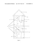
[0015] FIG. 2 is a rear view of one embodiment of the present invention.
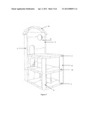
[0016] FIG. 3 is a left-side view of one embodiment of the present invention.
[0017] FIGS. 4a and 4b are expanded views of one embodiment of the present invention depicting selectively removable fascias.
[0018] FIG. 5 is a front aspect view of a second embodiment of the present invention.
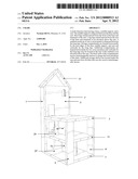
[0019] FIG. 6 is a front aspect view of a third embodiment of the present invention.
DETAILED DESCRIPTION OF THE INVENTION
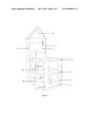
[0020] FIG. 1 is a front-quarter view of one embodiment of the multi-function chair of the present invention, in a "chair" configuration. Shown is base 1, a seat 3, and a seat-back 5. In some embodiments, the lower portion of the present invention comprises three levels, base 1, a middle support 11, and the seat 3 with middle support 11 disposed between base 1 and seat 3. Extending upward from base 1 are two long legs 7 and 7', at the rear corners of base 1, and two short legs 9 and 9', at the front corners of base 1. As shown, long legs 7 and 7' extend upward from base 1, extending beyond the seat 3 to delimit a frame for seat-back 5. The two short legs 9 and 9' terminate at or near seat 3 and provide the primary support thereof. In some embodiments, base 1 and middle support 11 may have cutouts at their respective corners such that the long legs 7 and 7' and short legs 9 and 9' are disposed in the cutouts, allowing for maximum strength and stability of the structure.
[0021] A roof member 13 may be mounted at the top of the structure, secured, for example, to the top edge of each long leg 7 and 7'. Roof member 13 may comprise variety of shapes, such as the "v-shaped" or the arched roof member 13 in FIG. 5. Additional roof structures may be integrated in seatback 5, such as that shown in FIG. 6.
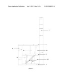
[0022] With reference to FIG. 2, in some embodiments of the present invention, the rear edges of base 1, middle support 11 and seat 3 in conjunction with long legs 7 and 7' delimit two compartments 15. Additional cross members 17 and 17' may be disposed between the two long legs 7 and 7' and at an elevation above the seat, delimiting additional compartments 15. For example, a first cross member 17' may be located at the top edge of the long legs 7 and 7' and the second cross member 17 may be disposed between seat 3 and the first cross member 17'.
[0023] Seat-back 5 is comprised of a plurality of thin seat-back panels 19 which are disposed and secured between long legs 7 and 7', delimiting the back walls of each compartment 15 on one side and the seat-back 5 on the other. As shown in FIG. 2, the panels 19 of each compartment 15 may include a variety of "cut-a-way" features such as apertures 21 depicting door openings or windows. Additional features such as staircases 23 and ladders may be disposed in each compartment 15 as desired.
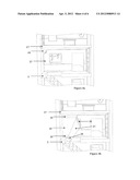
[0024] With reference to FIGS. 1 and 3, two storage shelves (where 29 and 29' point) located under seat 3 are formed by the arrangement of base 1, middle support 11, and seat 3. As shown, each of the shelves 29 and 29' may have a divider 31 disposed between the base 1 and middle support 11, and middle support 11 and seat 3, respectively. The dividers 31 maybe oriented substantially vertically (i.e. perpendicular to the orientation of the middle support 11, seat 3, or base 1), but need not be, depending on the preferred configuration. Storage shelves 29 and 29' may also contain a variety of other educational/entertainment elements such as staircases 33, ladders, miniature chairs, and tables. Optionally, the shelves 29 and 29' may simply be used for storage. Dividers 31 may comprise a variety of features such as apertures depicting door openings or windows.
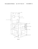
[0025] In some embodiments, base 1 may be omitted such that the two long legs 7 and 7' and two short legs 9 and 9' are the "four "legs" of the chair wherein the bottom of each are the feet of the chair. This configuration obviates the lower storage shelf 29' and its divider 31 as well as the bottom-most compartment 15. Additional configurations may omit middle support 11 or both base 1 and middle support 11. These configurations obviate the respective lower storage shelves 29 and 29' as well as the relevant compartments 15. For example, if only middle support 11 is omitted, then the bottom-most compartments 15 would then appear as a single large compartment.
[0026] As shown in FIGS. 4a and 4b, the rear-ward facing side of the panels 19 are capable of selectively and removably receiving interchangeable fascias 27. Fascias 27 may be made of a variety of materials such as paper, plastic, laminate, wood, or other like material; however fascias 27 may be flexible so that they are easily interchangeable. It is intended that the fascias 27 may have a variety of themed designs in order to add to the visual presentation of the present invention. For example, such themes could include, but are not limited to, castles, doll-houses, space-ships, dinosaurs, and the like. Additionally, fascias 27 may be comprised of a material that is capable of being written or drawn upon by permanent or erasable writing utensil such as an indelible or erasable marker, crayon, pen, pencil or the like. For example, such material may be a glossy, usually white material, i.e. a "whiteboard" or "dry-erase" board.
[0027] With reference to FIG. 4b, the fascias may be removably attached to panels 19 by a variety of fasteners 35 placed on either or both panels 19 and fascias 27 in corresponding locations. In one embodiment, fasteners 35 may comprise hook-and-loop fasteners. Accordingly, hook-and-loop strips, dots, or squares may be placed along the top and bottom perimeters of panels 19 wherein the corresponding hook-and-loop strips, dots or squares are placed on the top and bottom perimeters of fascias 27 In other embodiments, fasteners 35 may be a magnetically charged material such as metal or the such that the fascias 27 are selectively secured to the panels 19 by magnetic force. In yet other embodiments, double-sided tape or a like adhesive material may be used on either or both panels 19 and fascias 27 in corresponding locations. Further, in some embodiments, each divider 31 of storage shelves 29 and 29' may be capable of receiving fascias 27 having fasteners 35 on either side thereof.
[0028] In accordance with the foregoing, it should be understood that the relative size, shape, and dimensions of each component of the present invention need not be construed as limited. For example, as shown in FIG. 1, base 1, middle support 11, and seat 3 are shown as rectangular and substantially the same dimensions. However, other configurations may be readily apparent one skilled in the art, such as the rounded base 1, middle support 11, and seat 3 shown in FIG. 5. As shown in FIG. 1, long legs 7 and 7' and short legs 9 and 9' may have a rectangular cross-section, but any polygonal, cylindrical, or conical cross-section may be equally suitable, as shown in FIG. 5. Also, as shown in FIG. 1, short legs 9 and 9' are oriented such that the longer dimension of the rectangular cross-section of each are perpendicular to one another; however this configuration need be considered limiting as the orientation of the supports may vary as desired.
[0029] Further, as is understood in the art, each structural element and part thereof may be interconnected with each other through a variety of known means. For example, the structure may employ adhesives such as glues, epoxies, and the like, fasteners such as screws, nails, tacks, rivets, and the like, compression, press, and/or friction fitments, and combinations thereof. Accordingly, the method and means of assembling the structure of the present invention shall not be construed as limited by the description, claims, or drawings herein.
[0030] In the foregoing description, the present invention has been described with reference to specific exemplary embodiments thereof. It will be apparent to those skilled in the art that a person understanding this invention may conceive of changes or other embodiments or variations, which utilize the principles of this invention without departing from the broader spirit and scope of the invention. The specification and drawings are, therefore, to be regarded in an illustrative rather than a restrictive sense.
User Contributions:
Comment about this patent or add new information about this topic:
Images included with this patent application:
 |  |
 |  |
 |  |
 |
| New patent applications in this class: | |
| Date | Title |
|---|---|
| 2018-01-25 | Anti-ballistic chair |
| 2016-06-23 | Seat cover and vehicle seat |
| 2016-06-16 | Attachment apparatus to connect an electronic device holder to a seat structure |
| 2016-06-09 | Passenger seat with full seatback video display |
| 2016-06-02 | Vehicle seat |
| Top Inventors for class "Chairs and seats" | |
| Rank | Inventor's name |
|---|---|
| 1 | Johnathan Andrew Line |
| 2 | Larry P. Lapointe |
| 3 | Yukifumi Yamada |
| 4 | John W. Jaranson |
| 5 | Arjun Yetukuri |