Patent application title: Bottle with Multiple Openings
Inventors:
Jun Zhang (Guang Dong Province, CN)
Assignees:
ALLEN & THOMAS COSMETIC ACCESSORIES CO., LTD.
IPC8 Class: AA47G1924FI
USPC Class:
222565
Class name: Dispensing sifter, sprinkler or plural opening patterns
Publication date: 2012-03-29
Patent application number: 20120074179
Abstract:
A bottle includes a reservoir comprising a top main opening, a threaded
neck, and a shoulder adjacent the neck; a flexible, disc-shaped
dispensing device comprising a central bottom riser; grooves extending
from the riser, each groove having an outlet opening, top projecting
members each having one end of the outlet opening terminated thereon, and
a central recess with the projecting members therearound; an internally
threaded retaining ring secured to the neck to fasten the dispensing
device on the reservoir with the outlet openings being exposed; and a cap
comprising a bottom post inserted into the recess when the cap is secured
to the shoulder so as to flexibly deform both the recess and the riser to
seal the main opening.Claims:
1. A bottle comprising: a reservoir comprising an internal space, a top
main opening communicating with the space, an upper threaded neck, and a
stepped shoulder below and adjacent to the upper threaded neck; a
flexible, disc-shaped dispensing device comprising a central riser on the
bottom; a plurality of grooves extending from the central riser, each
groove having an outlet opening, a plurality of projecting members on the
top, each projecting member having one end of the outlet opening
terminated thereon, and a central recess with the projecting members
formed therearound, the central recess being under the central riser; a
retaining ring comprising internal threads adapted to threadedly secure
to the upper threaded neck to fasten the dispensing device disposed on
the top of the reservoir with the outlet openings being exposed; and a
cap comprising a bottom clamping edge and a post extending downward from
the center of the underside, the post being inserted into the central
recess when the clamping edge is secured to the stepped shoulder so as to
flexibly deform the central recess to press the central riser which
sealingly engages with the main opening.
2. The bottle of claim 1, wherein the number of the grooves is three, wherein one of the grooves is disposed around the central riser and the remaining two opposite grooves extend from the groove around the central riser, and wherein one of the two opposite grooves has a first branch and the other one of the two opposite grooves has a second branch with the outlet opening being disposed at end of either the first branch or the second branch.
3. The bottle of claim 1, wherein the dispensing device further comprises a recessed shoulder on the edge, the recessed shoulder being clamped by the retaining ring when the retaining ring and the dispensing device are secured together.
Description:
BACKGROUND OF THE INVENTION
[0001] 1. Field of Invention
[0002] The invention relates to bottles and more particularly to such a bottle having a dispensing device with a plurality of openings for uniformly dispensing liquid contained in the bottle, the dispensing device being releasably mounted on the bottle top.
[0003] 2. Description of Related Art
[0004] Typically, a bottle may have a single opening. However, the rate of discharging liquid contained in the bottle may be low. Alternatively, the bottle may have a plurality of openings. However, the rate of discharging liquid contained in the bottle may be too fast. Both disadvantages may bother a user. Moreover, the top of the bottle having the at least one opening provided therethrough is integrally formed with the bottle. Microorganisms may grow on the bottle top because it is not easy to clean it after use. This is not hygienic. Moreover, the bottle top is not leak proof. In often times, a user may have to clean the spilled liquid after opening the bottle cap. This may further bother the user. Thus, the need for improvement still exists.
SUMMARY OF THE INVENTION
[0005] It is therefore one object of the invention to provide a bottle comprising a reservoir comprising an internal space, a top main opening communicating with the space, an upper threaded neck, and a stepped shoulder below and adjacent to the neck; a flexible, disc-shaped dispensing device comprising a central riser on the bottom; a plurality of grooves extending from the riser, each groove having an outlet opening, a plurality of projecting members on the top, each projecting member having one end of the outlet opening terminated thereon, and a central recess with the projecting members formed therearound, the recess being under the riser; a retaining ring comprising internal threads adapted to threadedly secure to the neck to fasten the dispensing device disposed on the top of the reservoir with the outlet openings being exposed; and a cap comprising a bottom clamping edge and a post extending downward from the center of the underside, the post being inserted into the recess when the clamping edge is secured to the shoulder so as to flexibly deform the recess to press the riser which sealingly engages with the main opening.
[0006] The above and other objects, features and advantages of the invention will become apparent from the following detailed description taken with the accompanying drawings.
BRIEF DESCRIPTION OF THE DRAWINGS
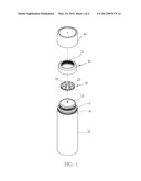
[0007] FIG. 1 is an exploded view of a bb according to the invention;
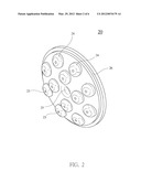
[0008] FIG. 2 is a perspective view of the dispensing device viewed from top;
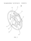
[0009] FIG. 3 is a perspective view of the dispensing device but viewed from bottom;
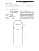
[0010] FIG. 4 is a perspective view of the assembled bb;
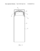
[0011] FIG. 5 is a longitudinal sectional view of the bottle; and
[0012] FIG. 6 is a view similar to FIG. 5 with the retaining ring removed and liquid contained in the bottle being discharged.
DETAILED DESCRIPTION OF THE INVENTION
[0013] Referring to FIGS. 1 and 6, a bb in accordance with the invention comprises the following components as discussed in detail below.
[0014] A reservoir 10 comprises an internal space 11 with liquid contained therein, a main opening 12 on a top center, the main opening 12 being in communication with the internal space 11, an upper threaded neck 13, and a stepped shoulder 14 below and adjacent to the upper threaded neck 13.
[0015] A dispensing device 20 is shaped as a disc and formed of elastomeric material. The dispensing device 20 comprises a central riser 21 on the bottom, and a plurality of grooves (three are shown) 22 extending from the central riser 21. One of the grooves 22 is formed around the central riser 21 and the remaining two opposite grooves 22 extend from the groove 22 around the central riser 21. Each of the opposite grooves 22 has an outlet opening 23 at an end. The outlet opening 23 communicates with the top of the dispensing device 20. The dispensing device 20 further comprises a plurality of projecting members 24 on the top, one end of the outlet opening 23 terminated on each projecting member 24, and a central recess 25 with the projecting members 24 formed therearound, the central recess 25 being arcuate in shape and directly under the central riser 21.
[0016] A retaining ring 30 comprises an internal threads 31 threadedly secured to the upper threaded neck 13 to fasten the edge of the dispensing device 20 when the dispensing device 20 is disposed on the top of the reservoir 10. Thus, most portion of the dispensing device 20 (i.e., the portion including the outlet openings 23) are exposed.
[0017] A cap 40 comprises a bottom clamping edge 41 and a post 42 extending downward from the center of the underside. The post 42 is lockingly inserted into the central recess 25 when the clamping edge 41 is secured to the stepped shoulder 14 by snapping (i.e., the cap 40 secured to the reservoir 10). The central recess 25 is flexibly deformed to press the central riser 21 to sealingly engage with the main opening 12. As a result, liquid contained in the space 11 is prevented from flowing out of the main opening 12.
[0018] One of the two opposite grooves 22 has a first branch 221 and the other one of the two opposite grooves 22 has a second branch 222. The outlet opening 23 is provided at end of the first branch 221 (or the second branch 222). A recessed shoulder 26 is formed on the annular edge of the dispensing device 20. The recessed shoulder 26 is clamped by the retaining ring 30 when the retaining ring 30 and the dispensing device 20 are secured together. It is envisaged by the invention that the dispensing device 20 can be detached for cleaning if such need arises.
[0019] Advantages and characteristics of the invention are described below. Liquid in the reservoir 10 is prevented from being discharged after securing the cap 40 to the reservoir 10. The grooves 22 each having an outlet opening 23 can uniformly flow the liquid out of the reservoir 10 when the reservoir 10 is upside down or inclined. The flexible projecting members 24 can be used as massaging members to rub the skin. The dispensing device 20 can be detached for cleaning after use.
[0020] In use, an individual may first remove the cap 40. Next, the individual may incline the reservoir 10 to cause liquid (e.g., lotion) therein to uniformly flow out of the outlet openings 23 via the main opening 12 and the grooves 22. Finally, the individual may rub the skin with the projecting members 24 which have the liquid applied thereon.
[0021] While the invention has been described in terms of preferred embodiments, those skilled in the art will recognize that the invention can be practiced with modifications within the spirit and scope of the appended claims.
User Contributions:
Comment about this patent or add new information about this topic:
Images included with this patent application:
 |  |
 |  |
 |  |
 |
| Similar patent applications: | |
| Date | Title |
|---|---|
| 2010-04-08 | Spray bottle with refill cartridge |
| 2010-04-15 | Spray bottle with refill cartridge |
| 2010-06-17 | Spray bottle with refill cartridge |
| 2012-01-12 | Bottle with integral supply tube |
| 2013-06-27 | Caulking gun with adjustable thrust mechanism |
| New patent applications in this class: | |
| Date | Title |
|---|---|
| 2016-04-07 | Powdered sugar scoop |
| 2014-08-07 | Full open disk dispensing closure |
| 2013-09-26 | Dispensing guide |
| 2013-09-12 | One-piece dispensing cap for a container |
| 2013-03-21 | Powder container |
| New patent applications from these inventors: | |
| Date | Title |
|---|---|
| 2010-11-11 | Pressable pen |
| Top Inventors for class "Dispensing" | |
| Rank | Inventor's name |
|---|---|
| 1 | Nick E. Ciavarella |
| 2 | John J. Mcnulty |
| 3 | Robert L. Quinlan |
| 4 | Andrew Jones |
| 5 | Heiner Ophardt |