Patent application title: DISMOUNTING DEVICE FOR BEARINGS
Inventors:
Michael Mueller (Bad Staffelsdein, DE)
Assignees:
MUELLER-KUEPS, L.P.
IPC8 Class: AB25B27073FI
USPC Class:
29261
Class name: Central screw, work-engagers around screw work-engager arms along or parallel to screw pivotal arms
Publication date: 2012-02-16
Patent application number: 20120036690
Abstract:
A bearing dismounting device includes a body, a rod, several clamping
arms, a tightening element, and an adjusting element. Each of the
clamping arms is pivotally installed around the body. The center of the
body has a through hole for the rod to mount therein. One end of the rod
has a positioning part, and its other end has an operating part. Each of
the clamping arms extends a buckling part. The central position on the
outer side of each of the clamping arms has an accommodating part. The
tightening element surrounds the accommodating parts of the clamping
arms. Both ends of the tightening element have an adjusting element,
respectively, for urging against the tightening element, thereby
positioning the clamping arms.Claims:
1. A bearing dismounting device, comprising: a body having at least three
pivotal connecting parts at equal spacing around it and a through hole at
its center; a rod going through the through hole of the body, whose both
ends are on opposite sides of the body with one end having a conic
positioning part and the other end having an operating part; at least
three clamping arms, one end of each of which is pivotally connected to
the pivotal connecting part of the body via a pivotal connecting element
and the other end has a buckling part toward the axial direction of the
through hole of the body and on the same side of the positioning part of
the rod, wherein an accommodating part is formed between the pivotal
connecting position of each of the clamping arm and the buckling part and
on the outer side of the clamping arm; and a tightening element
surrounding the accommodating parts of the three clamping arms, with an
adjusting element provided on opposite ends thereof for tightening and
positioning the three clamping arms.
2. The bearing dismounting device of claim 1, wherein the inner surface of the accommodating part is a circularly curved surface and the tightening element urges against the circularly curved surface.
3. The bearing dismounting device of claim 1, wherein the tightening element is a metal link, the adjusting element includes two blocks and a first screw bar, the two blocks connect to both ends of the tightening element, each of the blocks has a first screw hole, and the first screw bar goes into the first screw holes of the two blocks to adjust the tightness of the tightening element.
4. The bearing dismounting device of claim 3, wherein the other side of the tightening element opposite to the adjusting element has a fixing element with a concave part corresponding to the accommodating part of the clamping arm, a connecting section extends from above and below the concave part, each of the connecting sections has a second screw hole horizontally, each of the second screw holes is inserted with a second screw bar, and the second screw bar is also screw-connected to above and below the corresponding accommodating part.
Description:
BACKGROUND OF THE INVENTION
[0001] 1. Field of Invention
[0002] The invention relates to a dismounting device and, in particular, to a device that dismount a bearing from an axle.
[0003] 2. Related Art
[0004] Traditionally, one often uses a hammer to hit a bearing in order to dismount it from an axle. However, such a method may easily make the bearing oblique with respect to the axle, making it more difficult to dismount. Moreover, if the bearing is still in good condition and is only dismounted for other purposes, hitting the bearing is likely to cause damages thereon. Apparently, the conventional bearing dismounting method needs to be improved.
SUMMARY OF THE INVENTION
[0005] An objective of the invention is to provide a bearing dismounting device that uses three clamping arms to hold the bearing. The positioning part of a rod urges against the end of the axle where the bearing is mounted. By hitting the end of the axle, the bearing gradually parts from the axle. This mechanism can readily dismount the bearing without damaging it.
[0006] To achieve the above-mentioned objective, the disclosed bearing dismounting device includes: a body, a rod, at least three clamping arms, and a tightening element.
[0007] The body has at least three pivotal connecting parts around it corresponding to the clamping arms. The center of the body has a through hole. The rod goes through the through hole of the body. Both ends of the rod are on opposite sides of the body. One end of the rod has a conic positioning part, and the other end has an operating part. One end of each of the clamping arms is pivotally connected to the pivotal connecting part via a pivotal connecting element. The other end has a buckling part toward the axial direction of the through hole on the body and on the same side of the positioning part of the rod. An accommodating part is provided between the pivotal connecting position of each of the clamping arms and the buckling part and on the outer side of the clamping arm. The tightening element surrounds the accommodating parts of the three clamping arms. Both ends of the tightening element have an adjusting element, respectively, to urge against the tightening element, thereby positioning the three clamping arms.
BRIEF DESCRIPTION OF THE DRAWINGS
[0008] These and other features, aspects and advantages of the invention will become apparent by reference to the following description and accompanying drawings which are given by way of illustration only, and thus are not limitative of the invention, and wherein:
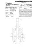
[0009] FIG. 1 is a three-dimensional exploded view of the invention;
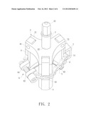
[0010] FIG. 2 is a three-dimensional assembly view of the invention;
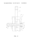
[0011] FIG. 3 is a side view of the invention;
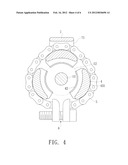
[0012] FIG. 4 is a bottom view when the tightening element of the invention holds the clamping arms tightly;
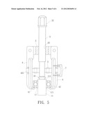
[0013] FIG. 5 is a schematic view showing the invention and the bearing before it is dismounted; and
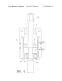
[0014] FIG. 6 is a schematic view showing the invention and the bearing after it is dismounted.
DETAILED DESCRIPTION OF THE INVENTION
[0015] The present invention will be apparent from the following detailed description, which proceeds with reference to the accompanying drawings, wherein the same references relate to the same elements.
[0016] Please refer to FIGS. 1 to 3 for an embodiment of the disclosed bearing dismounting device. It is used to dismount a bearing 12 mounted on an axle 11. The dismounting device includes: a body 2, a rod 3, at least three clamping arms 4, and a tightening element 5.
[0017] The body 2 has at least three pivotal connecting parts 21 separated at equal space for the clamping arms 4. For example, each neighboring two pivotal connecting parts are separated by 120 degrees. The center of the body 2 has a through hole 22.
[0018] The rod 3 goes through the through hole 22 of the body 2. Both ends of the rod 3 are on opposite sides of the body 2. One end of the rod 3 has a conic positioning part 31, and the other end has an operating part 32.
[0019] One end of each of the clamping arms 4 is pivotally connected to the pivotal connecting part 21 on the body 2 via a pivotal connecting element 41. The other end has a buckling part 42 toward the axial direction of the through hole 22 of the body 2 and on the same side of the positioning part 31 of the rod 3. An accommodating part 43 is provided between the pivotal connecting position of each of the clamping arms 4 and the buckling part 42 and on the outer side of the clamping arm 4.
[0020] The tightening element 5 surrounds the accommodating parts 43 of the three clamping arms 4. Both ends of the tightening element 5 have an adjusting element, respectively, to urge against the tightening element 5, thereby positioning the three clamping arms 4. In this embodiment, the inner surface of the accommodating part 43 is a circularly curved surface 431. The tightening element 5 urges against the circularly curved surface 431 of the accommodating part 43.
[0021] Besides, the tightening element is made of a metal, such as a chain. The adjusting element 6 includes two blocks 61 and a first screw bar 62. The two blocks 61 connect to both ends of the tightening element 5. Each of the blocks has a first screw hole 611. The first screw bar 62 goes into the first screw holes 611 of the two blocks 61. Turning the first screw bar 62 can adjust the tightness of the tightening element 5.
[0022] On the side of the tightening element 5 opposite to the adjusting element 6 is provided with a fixing element 7. The fixing element 7 has a concave part 71 corresponding to the accommodating part 43 of the clamping arm 4. A connecting section 72 is formed above and below the concave part 71, respectively. Each of the connecting sections 72 is formed with a second screw hole 721 horizontally. Each of the second screw holes 721 is inserted by a second screw bar 73. The second screw bar 73 is further screwed above and below the accommodating part 43. This limits the tightening element 5 above the clamping arm 4. Even when dismounting the adjusting element 6 and thus loosening the tightening element 5, the tightening element 5 would not fall from the clamping arm 4.
[0023] Please refer to FIGS. 4 to 6. To use the device, the user first slightly turns the clamping arms 4 open. Afterwards, the buckling part 42 of each of the clamping arms 4 urges inward against the surrounding of the surface 121 of the bearing 12 that is farther from the body 2. At the same time, the inner side of each of the clamping arms 4 gets close to the surrounding of the bearing 12. The first screw bar 62 of the adjusting element 6 is turned tight, so that there is an urging effect from the tightening element 5 toward the accommodating parts 43 of the clamping arms 4. This mechanism firmly restricts the three clamping arms 4 that are holding the bearing 12, preventing them from falling off in the subsequent dismounting task. Afterwards, the positioning part 31 of the rod 3 is made to urge against the end portion 111 of the axle 11 on which the beating 12 is mounted. One then uses a hitting tool, such as a hammer, to hit the operating part 32 of the rod 3. Under continuous hits, the rod 3 gradually departs from the bearing 12. Eventually, the bearing completely parts from the axle 11.
[0024] In summary, the invention uses the three clamping arms and the tightening element to firmly hold the bearing. By continuously hitting the rod, the axle is pushed to depart from the bearing gradually. Apparently, the invention has the feature that the bearing can be quickly and conveniently removed without being damaged in comparison with the prior art.
[0025] Although the invention has been described with reference to specific embodiments, this description is not meant to be construed in a limiting sense. Various modifications of the disclosed embodiments, as well as alternative embodiments, will be apparent to people skilled in the art. Therefore, it is contemplated that the appended claims will cover all modifications that fall within the true scope of the invention.
User Contributions:
Comment about this patent or add new information about this topic:
Images included with this patent application:
 |  |
 |  |
 |  |
 |
| Similar patent applications: | |
| Date | Title |
|---|---|
| 2009-05-14 | Crimping device for electrical crimping and sealed crimping |
| 2009-12-10 | Clamping device for flexible substrate and method for fabricating the same |
| 2009-12-10 | Clamping device for flexible substrate and method for fabricating the same |
| 2010-02-11 | Secondary positioning device for workpiece machining |
| 2010-12-23 | Variable positioning device for a crimping tool, and crimping tool |
| New patent applications in this class: | |
| Date | Title |
|---|---|
| 2016-06-02 | Puller |
| 2013-06-20 | Structure of the driving axis of a puller |
| 2012-03-22 | Pin extraction tool |
| New patent applications from these inventors: | |
| Date | Title |
|---|---|
| 2013-05-02 | Checking device for checking automotive suspension system |
| 2012-02-23 | Grinding workpiece |
| 2012-02-16 | Bearing mounting and dismounting tool |
| 2012-02-09 | Mounting and dismounting device for cylindrical bodies |
| 2008-12-25 | Tool for bearings |
| Top Inventors for class "Metal working" | |
| Rank | Inventor's name |
|---|---|
| 1 | Levi A. Campbell |
| 2 | Robert E. Simons |
| 3 | Branko Sarh |
| 4 | Richard C. Chu |
| 5 | Shou-Shan Fan |