Patent application title: ELECTRODE SYSTEM FOR TRANSDERMAL CONDUCTION OF ELECTRIC SIGNALS, AND A METHOD OF USE THEREOF
Inventors:
Albert Holzhacker (Sao Paulo - Sp, BR)
Assignees:
Timpel S.A.
IPC8 Class: AA61B504FI
USPC Class:
600391
Class name: Structure of body-contacting electrode or electrode inserted in body means for attaching electrode to body adhesive
Publication date: 2011-11-24
Patent application number: 20110288393
Abstract:
There is disclosed a system of electrodes used for transdermal conduction
of electric signals and a method of use thereof, the said system
comprising a plurality of electrode parts (17, 58, 58') connected by
means of electrical conductors (17', 68) to electric impedance tomography
apparatuses, as well as other devices, the said parts being secured to
the outer side (15a, 54a, 54'a) of a flexible and porous blade (15, 54c,
51') coated on both sides thereof by layers of electrically conductive
and adhesive materials, such electrically conductive materials being in
mutual contact through the pores (74) of the said blade, the inner face
of the latter being removably secured, by means of adhesion, to the skin
of the patient (65). The invention comprises means for positioning the
said electrode parts, as well as means for external protection thereof
and of their respective conductors.Claims:
1. A system of electrodes for transdermal conduction of electric signals
characterized by comprising a plurality of electrode parts mechanically
and electrically associated to the distal ends of cables intended to
carry electric signals to at least one equipment intended for application
of electrical stimuli or detection of electric signals, and a low-cost
portion comprising a flexible blade coated on both sides thereof with
layers of adhesive materials and electrically conductive materials, the
layers of electrically conductive materials of both sides being in mutual
electrical contact, the first side of the said flexible blade having
removably adhered thereto the said electrode parts that establish
electrical contact, by juxtaposition, with the electrically conductive
material that coats the said first side and the second side of the said
blade, being removably attached to the skin of the patient, the
electrical contact of the latter with the electrically conductive
material that coats the said second side being provided by means of
juxtaposition.
2. A system of electrodes, as claimed in claim 1, characterized in that the said layers that coat at least one of the sides of the said flexible blade are embodied as portions with defined dimensions and locations.
3. A system of electrodes, as claimed in claim 2, characterized in that at least one of the said layers of adhesive material forms portions that surround the said conductive portions.
4. A system of electrodes, as claimed in claim 2, characterized in that the said portions have dimensions that substantially correspond to the dimensions of the conductive parts of the electrode parts juxtaposed thereto.
5. A system of electrodes, according to claim 1, characterized in that the said adhesive materials and the said conductive materials consist in solid gels.
6. A system of electrodes, as claimed in claim 1, characterized in that the electrically conductive material of at least one of the said layers is simultaneously an adhesive material.
7. A system of electrodes, as claimed in claim 6, characterized in that the said simultaneously conductive and adhesive material consists in a solid gel.
8. A system of electrodes as claimed in claim 6, characterized in that the said low-cost portion comprises a strip comprising a central supporting element made of a flexible material coated on its first and second sides, respectively by means of a first and a second layers of a simultaneously conductive and adhesive material, which are placed in electrical contact through the openings of the said central supporting element made of flexible material.
9. A system of electrodes, as claimed in claim 8, characterized in that the said low-cost portion comprises a supporting band made of a flexible and electrically insulating material, having secured by adhesion to its inner side the said first layer of the said conductive and adhesive material.
10. A system of electrodes as claimed in claim 8, characterized in that the said first layer of conductive and adhesive material, secured by adhesion and in contact with the said inner side of the said band, is a part of the said strip which opposite side is coated with the said second layer.
11. A system of electrodes, as claimed in claim 10, characterized in that the said band is provided with cutouts with defined positions that allow access, from the outer side of the said band, to the areas of contact of the said first layer with the electrically conductive portions of the electrode parts fitted with small clearance within the said cutouts.
12. A system of electrodes as claimed in claim 1, characterized in that the electrical conduction cables associated with each electrode parts assembly are grouped in cable bundles.
13. A system of electrodes, as claimed in claim 8, characterized in that the said band is provided, along the longitudinal borders thereof, with foldable flaps, provided with cutouts for accommodating the said cable bundles.
14. A system of electrodes, according to claim 6, characterized in that the said low-cost portion comprises a band of flexible and electrically insulating material, coated on its inner side with a first layer of conductive and adhesive material and on its inner side with a second layer of conductive and adhesive material, the said first and second layers being in electrical contact through pores provided in the said band.
15. A system of electrodes, as claimed in claim 14, characterized in that at least one of the said layers of conductive and adhesive material consists of individual segments.
16. A system of electrodes, as claimed in claim 1, characterized by comprising means for positioning the said electrode parts.
17. A system of electrodes as claimed in claim 16, characterized in that the said positioning means are provided in the form of visual indication signals or insignia.
18. A system of electrodes as claimed in claim 16, characterized in that the said positioning means are provided by mechanical elements.
19. A system of electrodes as claimed in claim 18, characterized in that the said positioning elements comprise elements in high-relief juxtaposed to the said outer side of the said band.
20. A system of electrodes as claimed in claim 19, characterized in that the said positioning means comprise a slab of soft material extending along the region occupied by the electrodes, provided with openings that leave uncovered the areas of contact of the electrode parts.
21. A system of electrodes as claimed in claim 19, characterized in that the said positioning means comprise a segmented slab defining a plurality of positioning elements mutually spaced apart from one another both in the lengthwise direction and across the width of the said band.
22. A system of electrodes as claimed in claim 16, characterized in that the said positioning means comprise a template provided with means for retaining the said electrode parts.
23. A system of electrodes as claimed in claim 22, characterized in that the said template constitutes an auxiliary device.
24. A system of electrodes as claimed in claim 22, characterized in that the said template is comprised by the band without the said strip, having the borders of the cutouts provided with adhesive stripes, each electrode part having at least one of its dimensions equivalent to the sum of the dimension of the said cutout and the width of the said stripes.
25. A method of use of a system of electrodes for transdermal conduction of electric signals transmitted or detected by means of cables connected to electronic equipment items as claimed in claim 1, characterized by comprising the steps of: positioning the electrode parts at the locations and at the distances provided for the use of the said equipment items; placement of the conductive portions of the said electrode parts in electrical contact with a first layer of conductive material which coats a side of a flexible and porous blade which second side is coated with a layer of conductive and adhesive material for contact with the skin of the patient; superposition of the outer protection means of the electrode parts and respective cables.
26. A method, as claimed in claim 25, characterized in that the said positioning is effected with the aid of positioning means.
27. A method, as claimed in claim 26, characterized in that the said positioning means comprise openings in a band made of a flexible material.
28. A method, as claimed in claim 26, characterized in that the said positioning means comprise an external template.
29. A method, as claimed in claim 26, characterized in that the said positioning means comprise graphic signals or insignia printed on a blade of flexible and porous material.
30. A method, as claimed in claim 26, characterized in that the said positioning means comprise elements in high-relief.
31. A method, as claimed in claim 25, characterized in that the said placement of the conductive portions is preceded by the removal of a protective film.
32. A method, as claimed in claim 25, characterized in that the said placement of the conductive portions comprises the superposition of the said template over the electrode parts directly on the strip previously placed on the skin of the patient.
33. A method, as claimed in claim 25, characterized in that the said superposition of protective means is achieved by means of the folding of flaps provided in the said band.
34. A method, as claimed in claim 25, characterized in that the said superposition of protective means is achieved by means of the permanence of the said template after the same having been superimposed on the said strip.
Description:
FIELD OF THE INVENTION
[0001] The present invention relates to the electrodes used to apply transdermal electrical stimuli to patients and/or to detect electric signals from patients, such as sets of electrodes used in electrical impedance tomography, however without being limited to the latter.
DESCRIPTION OF THE PRIOR ART
[0002] The medical application of electrodes connected to specific equipment intended for electrical stimulation or detection of electric signals comprehends both the application of currents or voltages through the skin, examples thereof comprising transcutaneous nerve or muscle stimulation and functional electrical stimulation, such as the detection of electric signals exemplified by the electrocardiogram, the electroencephalogram, and the electromyiogram, as well as techniques whereby is applied an electric signal through the skin, simultaneously measuring the resulting signals, as occurs with electrical impedance tomography.
[0003] The electrical impedance tomography--generally known by the acronym EIT: Electrical Impedance Tomography--is an already known technique which consists in placing a plurality of electrodes in contact with the skin of the patient on a given region, and performing a series of steps comprising the injection of a current between the electrodes of a pair of electrodes, measuring the electrical potentials of the remaining electrodes, and repeating this step for all the electrodes of the entire set of electrodes. The measured values are sent to data processing equipment and are subjected to a treatment, which results in an image showing the electrical impedance within the region of interest.
[0004] Contrary to other techniques used to follow up the conditions of the patient, the EIT is suitable for continuously monitoring the condition of the patient, due to being non-invasive and due to not involving risks that might limit the number and frequency of monitoring actions, such as occurs, for example, with X-rays.
[0005] Since the distance between the points on the skin whereto the electrodes are attached may vary, either due to the effects of the patient's breathing (in the case of thoracic or abdominal monitoring) or even due to movements from the part of the patient, it is necessary that the electrode supporting element, normally configured as a strap, be capable of following these movements, in order to warrant permanent contact between the electrodes and the skin. Patent application No. BR PI0704408, of the same filing applicant of the instant application, illustrated in FIGS. 1 and 2 of the instant application, shows an electrode strap formed of a strip of fabric, both flexible and non-conductive, folded over itself in the longitudinal direction, resulting in a first section turned towards the patient and a second section oriented in the opposite direction, that is, externally to the patient. At spaced locations along the first section there is deposited a flexible conductive material, selectively in order to form a plurality of first circular or oblong regions 34, intended to contact the skin of the patient. Each of these zones has an extension 24 which extends towards the fold, surrounding the same and extending over the second section whereon it broadens forming a second zone 27, approximately coincident with the said first zone. This second zone serves to provide the electrical and mechanical connection to the points of contact 12 of a flexible, insulating and longitudinally non-deformable supporting strip 10, each point of contact being connected, by means of a flexible conductive track 39 embedded in the supporting strip, to a connector 42 which is provided with means of contact with the cabling that connects the said strap to the monitoring apparatus.
[0006] As may be observed in FIGS. 1 and 2, the structure in question is complex, which manufacture involves the performance of cutting/opening of windows 33 and the intermediary spaces 37 between the said first zones as well as between the said second zones in the fabric material, in addition to the selective placement of the conductive material, the installation of the supporting strip 10, etc.
[0007] Moreover, the absence of shielding means of the flexible tracks 39 might entail the detection of interfering signals, thereby compromising the accuracy of the results. One other disadvantage of the object of the cited application resides in the act of there being required the manual application of a conductive gel material on the zones 34 in order to improve the electrical contact with the skin of the patient.
[0008] There are presently known in the art several alternatives for the preparation of electrodes that dispense the manual application of such gels. In this regard, in U.S. Pat. No. 5,785,040, which title is Medical Electrode System, there is disclosed a system comprising a flexible, non-conductive backing material, having juxtaposed to the face turned towards the patient a plurality of patches made of a conductive material which face a flexible non-conductive blade. The latter is provided with openings or windows in the positions corresponding to the said pads, with dimensions slightly lesser than the same.
[0009] Through such windows each of these conductive patches contacts the upper side of a conductive gel plate, which lower face adheres to the skin of the patient. The conduction of electric signals is provided by flexible cables whose ends are permanently secured to the faces of the said conductive pads turned towards the said flexible backing material. Due to this last characteristic, the assembly cannot be washed, which fact compromises the reuse thereof. It is an expensive solution in light of its complex structure, and it application is limited.
[0010] In U.S. Pat. No. 6,788,979, which title is Electrical Stimulation Compress Kit there is disclosed a system whereby a flexible insulating strap, equipped with a Velcro® type closure means, is applied by tightening around a part of the body of a patient, exerting a compressive force thereon. At certain points, this strap is crossed through by metallic terminals of a fastener type which outer pin provides a point for attachment for the terminal of the cable that conducts the electric signals. The inner face of each terminal establishes an electrical contact with a conductive hook-loop fastener, which is removably attached to the strap by the adhesion of a first conductive gel layer. A second layer of conductive gel is in contact with the skin of the patient, the said layers being separated by a conductive web that may be made of metal or any other low resistivity material. This web becomes necessary due to the small size of the area of the terminal turned towards the patient, which fact might result in a concentration of the transcutaneous current. The conductive web provides a uniform distribution of the current throughout the entire surface of the pad, reducing the contact resistance with the skin and avoiding the occurrence of current concentration points. In addition to the disadvantage represented by the need to use the said pads, the described system has the disadvantage that the strap, in contact with the skin, is liable to become contaminated by sweat and other secretions; the washing or sterilization of this strap poses problems due to the presence of the metallic terminals and the Velcro® type adhesive means. The alternative consisting in the mere disposal of this strap constitutes a liability for the users of this system.
OBJECTS OF THE INVENTION
[0011] In view of what has been set forth above, one object of the present invention consists in the provision of a system of electrodes combining low cost and easy applicability to the patient.
[0012] One other object consists in the provision of a system of electrodes comprising low-cost elements, which disposal might not constitute an excessive burden to hinder the use thereof.
[0013] One further objective consists in the provision of a system that might dispense the use of conductive pads for uniform distribution of the current at the area of contact with the skin of the patient.
SUMMARIZED DESCRIPTION OF THE INVENTION
[0014] The objects set forth above, as well as others, are achieved by the invention by means of the provision of a system of electrodes formed of an assembly of electrode parts mechanically and electrically associated to the distal ends of the cables that conduct electric signals to an equipment provided for the application of electrical stimuli or for the detection of electric signals, such component parts being provided with an electrically conductive portion, and a low-cost portion comprising a support in the form of a flexible and porous blade, having applied to both faces thereof conductive portions formed by layers of electrically conductive materials, such layers being provided in electrical contact with one another, a first conductive portion, applied to the first side of the said blade placed in contact with the said electrode parts and a second conductive portion, applied to the second side of the said blade placed in contact with the skin of the patient, the removable attachment of the said electrode parts to the said low-cost portion being provided by a first layer of adhesive material juxtaposed to the said first side of the said blade, and the removable attachment of the said low-cost portion to the skin of the patient being provided by a second layer of adhesive material juxtaposed to the said second face of the said blade.
[0015] According to another characteristic of the invention, at least one of the said layers of adhesive material forms portions that surround the said conductive portions.
[0016] According to another characteristic of the invention, the electrically conductive material of at least one of the said layers is simultaneously an adhesive material and a conductive material.
[0017] According to another characteristic of the invention, the said blade is provided with means for positioning the said electrode parts.
[0018] According to another characteristic of the invention, the said positioning means are provided with visual indicators.
[0019] According to another characteristic of the invention, the said positioning means are provided by mechanical means.
[0020] According to another characteristic of the invention, the said positioning means are applied to the said first side of the said blade.
[0021] According to another characteristic of the invention, the said low-cost portion comprises a support which consists in a strap or strip of flexible fabric (textile) material, having affixed onto at least one of the faces thereof a flexible strip, which latter comprises a flexible and porous supporting blade coated on both faces thereof with layers of conductive and adhesive materials.
[0022] According to another characteristic of the invention, the said flexible strip, comprising the said layers of conductive and adhesive materials, is juxtaposed by means of adhesion of the said first layer of adhesive material to the inner face of a strap of electrically insulating fabric/textile material.
[0023] According to another characteristic of the invention, the said means for positioning the electrode parts are comprised by cutouts or openings in the said strap of fabric/textile material through which the said electrode parts are removably attached to the said first layer of adhesive material of the said strip.
[0024] According to another characteristic of the invention, the dimensions of the said cutouts are slightly larger than those of the conductive parts of the said electrode parts.
[0025] According to another characteristic of the invention, the said means used for positioning the electrode parts comprise protuberant elements provided in correspondence with the outer side of the said strap.
[0026] According to another characteristic of the invention, the said means used for positioning the electrode parts comprise a template.
[0027] According to another characteristic of the invention, the said simultaneously adhesive and conductive portions are constituted by at least one layer of solid gel.
[0028] According to another characteristic of the invention, the said flexible strip consists in a continuous strip.
[0029] According to another characteristic of the invention, the said flexible strip is interrupted between the said cutouts, the dimensions of the pieces of the said conductive strip being sufficient to occlude the said cutouts in the said strap.
[0030] According to another characteristic of the invention, the electrical contact between the said upper layers of conductive materials is provided by means of pores provided in the supporting blade of the said strip.
[0031] According to another characteristic of the invention, the said layers of electrically conductive materials and adhesive materials are applied directly over the said fabric/textile material strap.
[0032] According to another characteristic of the invention, the electrical contact between the said layers of conductive materials is provided by means of pores provided in the said fabric/textile material strap.
[0033] According to another characteristic of the invention, the materials of the said layers comprise a solid gel that is simultaneously conductive and adhesive.
[0034] According to another characteristic of the invention, at least one of the said solid gel layers is applied in a selective manner.
[0035] According to another characteristic of the invention, the said areas of mechanical fastening and electrical contact of the said electrode parts are provided by the said first solid conductive and adhesive gel layer applied selectively on the outer side of the said strap.
[0036] According to another characteristic of the invention, the said means for electrical contact and removable mechanical attachment to the skin of the patient are provided by the said second layer of solid conductive and adhesive gel applied selectively on the inner side of the said strap.
[0037] According to another characteristic of the invention, both layers of solid gel are selectively applied in the form of portions with defined dimensions and spacing distances, each of the portions on the outer side, forming the area of mechanical fastening and electrical contact of the electrode parts, in substantial alignment with the portion applied on the inner side of the said strap.
[0038] According to another characteristic of the invention, the said electrode parts are secured, in a semi-permanent manner, to the first layer by means of juxtaposition and slight pressure.
[0039] According to another characteristic of the invention, the said electrode parts comprise, individually, a conductive portion in the form of a conductive blade and a physical and electrical connection thereof with an electric signal conduction cable, the said conductive portion having a shape and size compatible with the said openings through which there is provided the contact of the said conductive portion with the said first conductive layer.
[0040] According to another characteristic of the invention, the said strap is provided with means for positioning the electrode parts.
[0041] According to another characteristic of the invention, the said positioning means comprise the said openings provided in the said strap.
[0042] According to another characteristic of the invention, the said positioning means are provided by a slab of low density flexible insulating material, such as rubber foam or synthetic resin, applied on the outer side of the said strap, provided with openings that are coincident with the said areas intended for mechanical fastening and electrical contact of the said electrode parts. According to another characteristic of the invention, the said slab is substantially continuous.
[0043] According to another characteristic of the invention, the said slab is segmented, being comprised of segments distanced from one another in the longitudinal and transversal directions of the said strap
[0044] According to another characteristic of the invention, the said strap is provided, along the longitudinal borders thereof, of flaps that are superimposed by folding on the region of the strap wherein are provided the said electrodes, providing a measure of protection thereto as well as to the cables associated therewith.
DESCRIPTION OF THE FIGURES
[0045] Further characteristics and advantages of the present invention will be better understood by means of the description of exemplary and non-limitative embodiments thereof, and of the figures to which such embodiments refer, wherein:
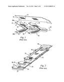
[0046] FIGS. 1 and 2 depict an electrode strap (belt) structured in accordance with the prior art, as described in patent application No. BR PI 0704408, filed by the same applicant of the instant application.
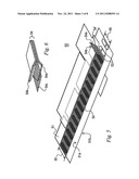
[0047] FIG. 3 shows a first embodiment of the inventive concept, using a flexible supporting strip, having applied on both sides thereof portions of conductive and adhesive materials.
[0048] FIG. 4 shows a second embodiment of the inventive concept, wherein the adhesive material is applied in the form of a continuous layer.
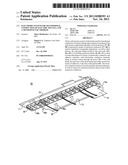
[0049] FIG. 5 shows, by means of a perspective view of the inner side, which remains in contact with the patient, a strap structured in accordance with the principles of the present invention.
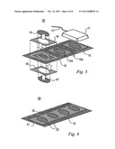
[0050] FIG. 6 shows, by means of a perspective view, a strip coated on both sides with materials that are simultaneously conductive and adhesive, which may be used together with the strap of the exemplary embodiment of the preceding figure.
[0051] FIG. 7 shows a perspective view of the outer face of the strap shown in FIG. 5, structured in accordance with the principles of the present invention.
[0052] FIG. 8 shows, by means of a perspective view, an electrode part used in connection with the present invention.
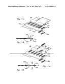
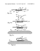
[0053] FIG. 9 shows, by means of cross-sectional schematic views, the various stages of the sequence of application of the strap to the patient.
[0054] FIG. 10 depicts the folding of the outer flaps of protection of the electrode parts and respective cables.
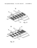
[0055] FIG. 11 depicts an additional embodiment of the invention.
[0056] FIG. 12 shows a variation of the additional embodiment depicted in the preceding figure.
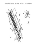
[0057] FIG. 13 shows an implementation of the mechanical positioning means of the electrode parts on the strap according to the present invention.
[0058] FIG. 14 illustrates an additional form of implementation of the means for positioning the electrode parts on the strap according to the present invention.
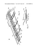
[0059] FIG. 15 illustrates another form of embodiment of the invention.
DETAILED DESCRIPTION OF THE INVENTION
[0060] FIG. 3 shows a first embodiment 30 of the invention, comprising a flexible strip 15, preferably made of fabric/textile material, coated with conductive parts with defined size and spacing 19 and 19', respectively applied on the first side 15a and on the second side 15b thereof, the electrical contact between the said conductive portions being provided by means of the material of the said strip, either by means of the porous texture thereof, or by means of pores opened by known means, such as by mechanical perforation (not illustrated in the figure). According to the principles of the invention the conductive materials of portions 19 and 19' comprise solid gels. As shown in the figure, the said portions 19 and 19' are substantially aligned with one another, that is, they occupy substantially coincident positions on the opposite sides of the said strip. Surrounding the said portions, there are provided regions 18 and 18' of adhesive material, respectively applied on the first and second sides of the said strip 15. This material, which may consist in a solid gel, provides the retention of the electrode parts 17 on the surface of the strip 15 and the contact of those parts with the conductive material 19, enabling the transmission to the latter of the electric signals that travel along the cables 17'. Due to the fact that the portions 19 e 19' are in mutual electrical contact, and the latter is in contact with the skin of the patient, the arrangement shown in FIG. 3 effectively provides the transmission of electric signals between the skin of the patient (not illustrated) and the connecting cable 17'. According to what is shown in the said figure, the dimensions of the contact area 16, formed by the conductive regions 19 and adhesive regions 18, correspond substantially to the dimensions of the lower part (not visible in the figure) of the electrode part 17, the said lower part comprising an electrically conductive area.
[0061] FIG. 4 illustrates a variation 40 of the arrangement shown in the preceding figure, differing therefrom in the fact that the adhesive gel layer 20 is applied in a continuous manner, this gel providing the means for removable retention of the electrode parts (not shown) and physical contact thereof with the conductive gel portions 21. The accurate positioning of the electrode parts may be aided by the provisions of positioning means, which latter in the said figure are the indicative signs 22 that are preferably printed on the surface of the strip 15.
[0062] Notwithstanding that FIGS. 3 and 4 exemplify strips wherein are employed conductive materials distinct from the adhesive materials, there may be used, in the invention, materials that simultaneously exhibit adhesive properties and conductive properties, such materials being known and available in the form of solid gel. Furthermore, the composition of the gel that is applied to the first side of the said strip 15 may be the same or different from that which is applied to the second side, since the latter is supposed to establish the contact with the skin of the patient, while the other is intended to contact the electrode parts.
[0063] A FIG. 5 illustrates a non-restrictive exemplary embodiment of the invention, whereto were added elements that complement the functionalities provided by the exemplary embodiments of FIGS. 3 and 4. This embodiment 50 comprises a strap of flexible non-conductive material 51, which inner surface 51a is intended to be placed in contact with the skin when applied to the patient, with the opposite side 51b being provided facing outwards to allow the installation of the electrode parts. As illustrated in FIG. 5, the strap 51 is provided with a plurality of cutouts with the shape of oblong openings spaced along a region that extends substantially along the center thereof.
[0064] According to the principles of the invention and as illustrated in FIG. 5, a strip 54 structured in accordance with the principles exemplified in the embodiments of FIGS. 3 and 4 is glued on the region occupied by the said openings, the width 55 thereof being sufficient to obstruct entirely the said openings. In practice, the said width 55 is slightly larger than the dimension 56 of the openings in the transversal direction of the strap, in order to ensure the full occlusion thereof. The said strip 54 is permanently bound to the inner side 51a of the strap 51, and it should be noted that the raising of one of the ends 54' thereof as illustrated in FIG. 5 constitutes a mere graphical resource intended to enhance the openings 52 and render the same more visible to the viewer hereof.
[0065] FIG. 6 illustrates the strip 54, by means of a view in perspective wherein the vertical dimension--the thickness--is considerably enlarged in order to evidence the elements that compose the same. As may be observed, the said strip comprises a central element or supporting blade 54c intercalated between a first layer of adhesive and conductive gel 54a and a second layer of adhesive and conductive gel 54b. The said central element 54c may be constituted by a screen which mesh size is substantially open, in order to allow, through the openings therethrough, the contact and mutual adhesion between the said first and second gel layers, that are electrically conductive, wherein there may be used a non-woven screen in a preferred embodiment of the invention. The characteristics of the said gel layers may be the same or may be mutually distinct, in light of their different functions. The gel of layer 54a, which stays adhered to the strap 51, should further allow the adhesion and removal of the electrode parts, as will be seen in the following. On the other hand, the layer 54b should allow the attachment and removal of the strap to/from the skin of the patient, and should thereby exhibit characteristics compatible therewith, without causing irritation or allergic reactions.
[0066] FIG. 7 shows the same strap, observed on its outer side, which side will stay exposed upon the application thereof to the patient. As may be seen in the figure, in this position the cutouts 52 allow selective access to the contact areas 57 of the conductive and adhesive gel layer 54a of the strip 54, such cutouts serving as means for positioning and spacing the electrode parts 58. For the assembly of the latter it will suffice to remove the protective film 49 and juxtapose, applying thereby a slight pressure, the said electrode parts against the said contact areas.
[0067] Still in accordance with FIG. 7, in a preferred embodiment of the invention, there are provided, parallel to the longitudinal axis of the said strap, flaps 69, 71, 73 and 74 intended to protect, by folding, the electrode parts and respective cables upon the assembly thereof on the strap. The said flaps may be provided with retention means upon the said folding, such as adhesive bands along the outer borders thereof or Velcro® type or equivalent closure means. However, these flaps may not be present in other embodiments.
[0068] According to the detail shown in FIG. 8, each electrode part comprises on the lower side thereof a conductive portion 59, which may comprise a metal plate--for example, made of copper, stainless steel, or an equivalent metal--or made of a conductive plastic material. Internally to the body of the part, preferably made of an insulating plastic, there is provided the union, preferably by welding 63, of the end of a cable 62 for carrying electric signals between the patient and the monitoring equipment, for example, an EIT apparatus. As illustrated in the figure, the dimensions of the opening 52 are provided to accommodate, with a minimal spacing gap, the portions 59 of the electrode parts 58.
[0069] FIG. 9 illustrates a preferred method of application of the strap to the patient, by means of a sequence of simplified sectional views corresponding to the cross-sectional plane 41 indicated in FIG. 7. The initial condition of the strap 50 is shown in FIG. 9-a, wherein there may be observed that the conductive and adhesive gel sides of the strip 54 are protected by disposable films: the film 64 protects the conductive and adhesive gel side 54b oriented towards the patient and the film 49 protects the conductive and adhesive gel side 54a oriented towards the strap 51 and accessible from the outside through the said openings 52 (not referenced in this figure).
[0070] The first step of the application method, illustrated in FIG. 9-b, consists in the removal of the film 49, represented by the arrow 67, thereby exposing the conductive and adhesive gel side 54a that forms the areas of contact with the said electrode parts (these areas of contact are referred with the numeral 57 in FIG. 7), in addition to becoming adhered to the inner side 51a of the said strap. To each of these exposed contact areas there is juxtaposed an electrode part 58, which adhesion is provided by the simple compression of the conductive side 59 against the surface of the said conductive and adhesive gel.
[0071] Subsequently, the electrode parts and their respective cables are protected by folding over the same the side flaps of the strap, if such flaps are present, as illustrated in FIG. 10. This figure illustrates the strap upon the first flap 69 having been folded to the position 69', becoming superimposed over the said electrode parts, there being noted that the cable assemblies 68, each of the same corresponding to a set of four electrode parts, extend to the outside through the cutouts 72'. After this first folding, the flap 71 is folded in the direction indicated by the arrow 71a, becoming superimposed over the already folded flap 69'. Subsequently, the cable assemblies 68 are deviated as indicated by arrows 68a, in order to be juxtaposed to the border 69b of the folded flap 69', and are brought together forming a set of cable assemblies which protuberates through the cutout present between the flaps 73 and 74. Finally, these last flaps are folded, as indicated by the arrows.
[0072] Subsequently, the assembly formed by the said strap carrying the said electrodes is applied to the patient. To that end, the protective film 64 of the conductive and adhesive gel layer 54b is removed, as indicated by the arrow 66 in FIG. 9-c. The assembly is then pressed against the skin of the patient, as illustrated in FIG. 9-d, whereby the retention thereof is provided by the conductive and adhesive gel 54b, which also intermediates the carrying of the electric signals. There is noted in this figure the protective flap 69' superimposed over the said electrode part. For better clarity of the figure, the remaining protective flaps have been omitted in the drawing.
[0073] As illustrated in FIG. 5, the strip 54 is provided in the form of a single piece, without interruptions between the adjacent openings 52. Notwithstanding the fact that the continuity of the strip provides a resistive path between the adjacent electrode parts in contact with the skin of the patient, the effect of such continuity is negligible, and does not substantially influence the electrical behavior of the assembly. Thus, for example, considering the typical values of 4 cm2 of contact area 57 for each electrode, a distance of 1.5 cm between the borders of adjacent electrodes, a thickness of 0.3 mm for the conductive gel layer and a gel resistivity ρ=1000 ohm-cm, there are obtained as a result the approximate values of from 10 to 20 kΩ between adjacent electrodes, while the resistance between the electrode part and the skin of the patient is of the order of only 5 to 10Ω.
[0074] However, the inventive concept disclosed herein also includes an assembly in which the strip 54 is segmented, that is, having interruptions between adjacent electrodes, with the said segments having dimensions that are slightly larger, both in length and in width, than the openings 52, in order to fully occlude the latter.
[0075] In an additional embodiment of the disclosed concept, the strip 54 is not used, and the gel layers 54a and 54b are deposited directly on the opposite sides of the strap 51. A first variant of that embodiment is shown in FIGS. 11-a and 11-b, of which the first shows a part of the said strap 50' seen in its internal side 51'a, that is, that which will be in contact with the patient, and the second is a cross-sectional view with the vertical dimension having been enlarged. As illustrated, in this embodiment there have been omitted the cutouts or openings 52 of the preceding embodiment. In the areas 74 corresponding to the positions of the electrodes there are practiced a plurality of small through-openings or pores, that provide communication between the outer side 51'b and the inner side 51'a of the strap 51'. Such openings may be obtained by mechanical means or by any other known means of perforation, and this communication may further be provided by the web itself of the strap 51', provided that the same is sufficiently porous.
[0076] Upon the provision of the porous areas 74, there are applied on opposite sides the conductive gel layers, to with, the internal layer, which is continuous, of the gel 54'b on the inner side 51'a of the strap and the outer layer 54'a, which is segmented, on the outer side 51'b of the strap, such gels being equivalent to the layers 54b and 54a, respectively, of the embodiment illustrated in FIGS. 5 and 6. This application may be provided using any known process, such as by spraying, silk-screen printing, offset printing, etc., provided that that there is maintained the alignment between the areas coated with adhesive and conductive gel and the porous areas 74, whose pores enable the physical and electrical contact between the said inner and outer layers.
[0077] In FIGS. 12-a and 12-b there is illustrated a constructive variation of the preceding embodiment, which differs from this latter only in regard of the inner layer of adhesive and conductive gel, which is deposited in segments 54''b, using the already cited application processes. It should be noted that, in this case, there should exist an alignment between the internal gel portions 54''b, the external gel portions 54'a and the areas 74, that is, these elements should be provided substantially coincident with one another. In a preferred embodiment of the invention, the dimensions of the segments 54''b and 54'a are substantially coincident with those of the conductive portions 59 of the electrode parts 58.
[0078] As mentioned in connection with FIGS. 5 and 7, the means for positioning the electrode parts 58 may be provided by the openings 52, as indicated in those figures. However, there may be used other positioning means, such as printed insignia, elements in relief glued on the outer surface of the strap, or equivalent elements. In FIG. 13 there is illustrated the use of a slab of soft elastic material 75, such as rubber foam, a plastic material or an equivalent material, extending along the region occupied by the electrodes. This slab is provided with openings or windows forming holes or frames 76 having dimensions compatible with those of the contact areas 57 that remain exposed at the bottom of the said holes, over which are applied the said electrode parts 58.
[0079] In order to provide an enhanced flexibility to the assembly, the positioning slab described in connection with the preceding figure may be segmented, as indicated in FIG. 14. In this figure, the positioning elements 77 are mutually distanced both in the lengthwise direction and across the width of the strap 80. This transversal distancing allows the use of a protective film 78, which covers the exposed areas 57 during the storage of the strap, and is removed at the time of use thereof.
[0080] Although the invention has been described with reference to specific exemplary embodiments, it should be understood that there may be introduced modifications therein by technicians skilled in the art, without deviation from the scope of the basic inventive concept thereof.
[0081] In an additional form of embodiment of the invention, the electrode parts are positioned separately with relation to the strap, by means of use of an auxiliary template, not illustrated in the figures, whereon these parts are mounted. After this mounting, the template carrying the electrode parts is applied to the strap 51, the said parts then remaining attached by adhesion to the said strap, which is subsequently applied to the patient. Optionally, the strip 51 will not be used, and the template with the electrode parts may be applied directly on the strap 54 having been previously applied on the skin of the patient, in which case the protection of the said parts and their respective cables may be provided by the template itself, or eventually by a protective band (not illustrated) placed externally. In another alternative form of embodiment of the invention, the template is constituted by the strap 51 per se without the strip 54. This embodiment is shown in FIG. 15, wherein the border of each cutout 52 is coated, on the outer side 51b of the strap, by adhesive stripes 79. The assembly of the electrode parts 58' shall be provided by superimposing the borders thereof onto the adhesive stripes, as indicated in the figure, and it should be noted that in this case at least one of the dimensions 81 of the said electrode part shall correspond to the sum of the dimension of the cutout 52 and the width of the said stripes. Upon mounting the electrode parts according to the illustration of FIG. 15, the flaps are folded as described in connection with FIG. 10. At the time of use, the strip 54 is applied to the skin of the patient, thereupon superimposing over this strip the said assembly formed by the said strap carrying the said electrode parts.
[0082] Therefore, the present invention is defined and delimited by the set of claims that follows.
User Contributions:
Comment about this patent or add new information about this topic:
| People who visited this patent also read: | |
| Patent application number | Title |
|---|---|
| 20130333907 | HAND-HELD POWER TOOL |
| 20130333906 | Machine Tool and Control Method |
| 20130333905 | Machine Tool and Control Method |
| 20130333904 | Machine Tool and Control Method |
| 20130333902 | SYSTEM AND METHOD FOR SODIUM AZIDE BASED SUPPRESSION OF FIRES |
Images included with this patent application:
 |  |
 |  |
 |  |
 |  |
 |
| New patent applications in this class: | |
| Date | Title |
|---|---|
| 2022-05-05 | Elastic wearable sensor |
| 2016-07-07 | Wireless cardiac event recorder |
| 2016-06-30 | Modular wearable sensor device |
| 2016-06-30 | Attachment device for attaching an electronic device |
| 2016-06-09 | Neural block determination |
| Top Inventors for class "Surgery" | |
| Rank | Inventor's name |
|---|---|
| 1 | Roderick A. Hyde |
| 2 | Lowell L. Wood, Jr. |
| 3 | Eric C. Leuthardt |
| 4 | Adam Heller |
| 5 | Phillip John Plante |